

-
Products -PCBA Manufacturing RF Connectors RF Cable Assemblys Embedded Antennas External Antennas Positioning Chips and Modules
RF Connectors

RF Cable Assemblys
Embedded Antennas
External Antennas
Positioning Chips and Modules


 Language


Language


In the precise world of Real-Time Kinematic (RTK) Global Navigation Satellite System (GNSS) positioning, the pursuit of centimeter-level accuracy is a relentless battle against error. While much attention is rightly paid to the sophisticated algorithms and processing power of the GNSS receiver module itself, there is a critical, often underappreciated, component that serves as the first line of defense in this battle: the antenna. Among antenna designs, the Choke Ring Antenna stands as the gold standard for high-precision applications, a specialized tool whose sole purpose is to ensure that the data fed to the RTK engine is as pure and uncontaminated as possible.
To understand the choke ring's paramount importance, one must first grasp the primary enemy of high-precision GNSS: multipath error. Multipath occurs when a satellite's signal does not travel along a direct, line-of-sight path to the antenna. Instead, it reflects off surrounding surfaces—the glass facade of a building, a body of water, the body of a vehicle, or even the ground itself—before finally arriving at the antenna. These reflected signals are delayed copies of the original and, when processed by the receiver, corrupt the precise timing measurements that are fundamental to determining position. For standard GNSS, multipath can cause errors of several meters. For RTK, which relies on the integrity of the carrier-phase measurement to within a fraction of a wavelength (just a few centimeters), multipath is a debilitating poison that can prevent integer ambiguity resolution entirely or lead to dangerously inaccurate "fixed" solutions.
The choke ring antenna is engineered from the ground up to be a multipath mitigation device. Its distinctive, cumbersome, and instantly recognizable design—a central radiating element surrounded by concentric, circular troughs (the "rings")—is not an aesthetic choice but a highly functional one, the result of rigorous electromagnetic theory. While a standard patch antenna might accept signals from all directions with little discrimination, the choke ring is a discerning gatekeeper. It excels at amplifying the desired direct signals arriving from above (from the sky) and ruthlessly suppressing the unwanted reflected signals arriving from low elevations, near the horizon.
The development of the choke ring antenna is deeply intertwined with the history of satellite geodesy and early high-precision GPS. Its origins lie in the need for reference stations—both for scientific networks like the IGS (International GNSS Service) and for national geodetic surveys—to establish a stable, unwavering point of reference. The data from these stations are used to measure tectonic plate movement, create precise orbital models, and define the fundamental coordinate frameworks of the planet. For such applications, the integrity of the data is paramount, and even minuscule multipath errors are unacceptable over long observation periods. The choke ring design provided the necessary performance to meet these extreme demands.
In an RTK system, the choke ring is most commonly deployed at the base station. The base station's role is to generate correction data; any error in its position, which is assumed to be known perfectly, will be directly transmitted to and incorporated by all rovers in the network. Therefore, ensuring the base station antenna is virtually immune to multipath is the highest priority. A rover using a standard antenna might experience localized multipath errors that affect only its own position, but a base station with multipath error will corrupt the entire operation for every user relying on it. This is why permanent reference stations, which form the backbone of national RTK networks (CORS - Continuously Operating Reference Stations), are almost universally equipped with high-quality choke ring antennas.
However, the use of choke rings is not exclusively limited to base stations. Rover applications that demand the ultimate in reliability and accuracy, even in challenging multipath environments, also employ them. This includes scientific fieldwork in complex terrain, precision monitoring of structural deformation on large buildings or dams, and aerial mapping missions using drones or aircraft where reflections from the vehicle's body and the ground below can be significant.
In summary, the RTK choke ring antenna is not merely an accessory but a foundational component of a high-integrity positioning system. It is the sentinel that guards the gateway of data, using its unique physical design to perform a critical filtering function that enables the digital processing inside the receiver to achieve its theoretical potential. Its overview reveals a device where form is perfectly married to function, a physical solution to an electromagnetic problem that remains as relevant today as when it was first conceived.
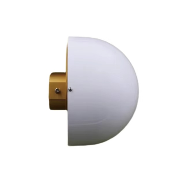
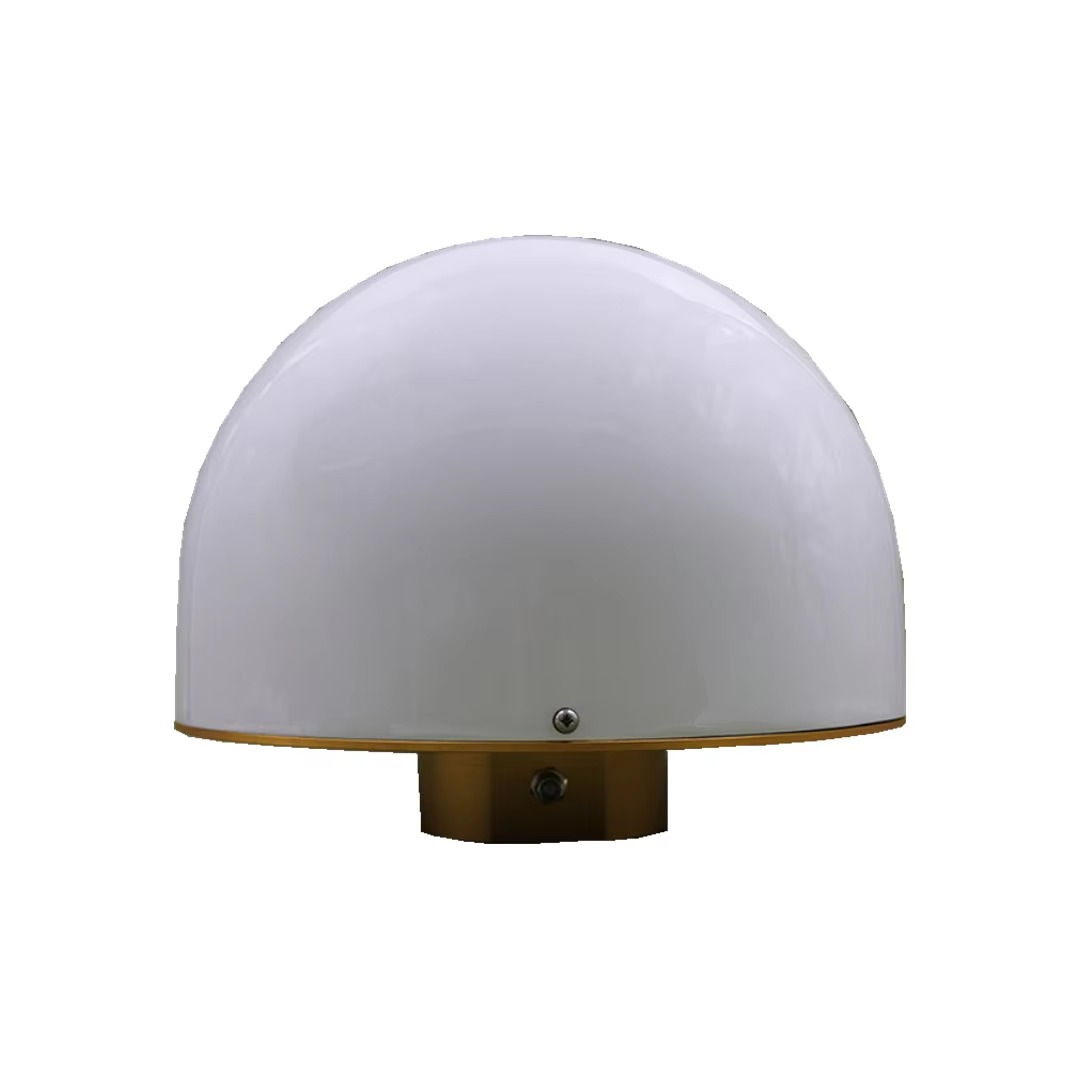
The formidable appearance of a choke ring antenna—its weight, size, and concentric rings—is a direct physical manifestation of its underlying electromagnetic design principles. Every aspect of its construction, from the materials used to the precise geometry of its rings, is meticulously engineered to control the antenna's radiation pattern and achieve its primary goal: maximizing the gain towards signals from the sky and minimizing it towards signals from the horizon and below.
Core Components and Their Function:
The Radiating Element: At the very center of the antenna lies the actual element that receives the GNSS signals. This is typically a precisely engineered patch antenna—a small, flat element often circular or square in shape, printed on a dielectric substrate. This patch is designed to be inherently good at receiving the right-hand circularly polarized (RHCP) signals broadcast by GNSS satellites. Its performance is optimized for the specific GNSS frequency bands it is intended to receive (e.g., L1, L2, L5). This element is responsible for the basic reception of the signal.
The Ground Plane: Directly beneath the radiating patch is a conductive ground plane. Its primary functions are to:
Provide a stable reference for the patch antenna, ensuring consistent performance.
Reflect incoming signals upwards towards the patch, enhancing gain for high-elevation satellites.
Block signals from below the antenna, providing the first level of multipath rejection. However, a simple, flat ground plane is insufficient for high-precision work, as it does not effectively handle signals arriving at low angles just above the horizon.
The Choke Rings (The Key Innovation): This is the defining feature. The rings are not simple baffles; they are carefully designed annular cavities. Each ring is a trough with a depth and width determined by specific electromagnetic calculations. The most common design is the Corrugated Ground Plane or Shallow Cavity Choke Ring.
Principle of Operation: Each ring cavity acts as a high-impedance surface for specific frequencies. When an electromagnetic wave (the GNSS signal) traveling along the plane of the antenna encounters the ring, it sees a surface that is very difficult to excite electrically—it presents a high impedance. This has a critical effect: it prevents radio frequency currents from flowing across the surface of the antenna.
Suppressing Surface Waves: Reflected multipath signals often travel as "surface waves" along the ground plane. If these currents are allowed to reach the radiating patch, they will induce a voltage and be received as a valid signal. The choke rings' high impedance effectively "chokes" these surface currents (hence the name), preventing them from propagating to the feed point of the antenna.
Depth Calculation: The depth of the rings is not arbitrary. For optimal performance, the depth of the cavity is designed to be approximately one-quarter of the wavelength (λ/4) of the target GNSS frequency in the dielectric material filling the cavity. A depth of λ/4 creates a short-circuit at the bottom of the cavity that transforms into an open-circuit (high impedance) at the top surface, precisely at the desired frequency. Modern antennas are multi-frequency, requiring complex ring designs that work effectively across L1, L2, and L5 bands, often involving a compromise in depth or more advanced, multi-ring structures.
Physical Construction and Materials:
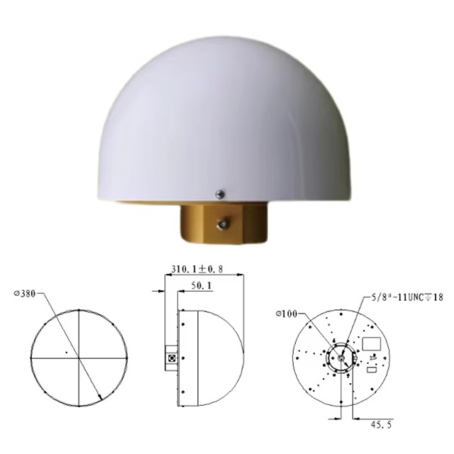
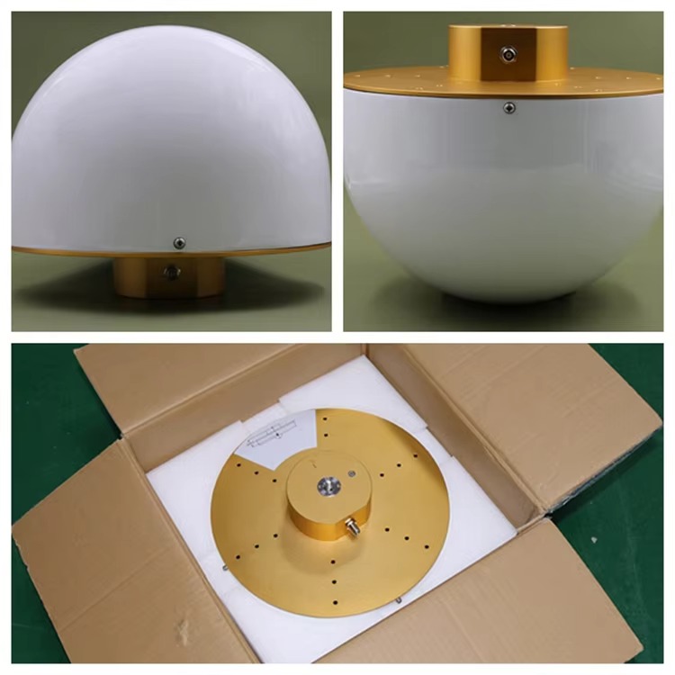
Body and Rings: The main body of a choke ring antenna is typically machined from a single block of high-quality, conductive metal like aluminum or brass. This ensures excellent electrical conductivity and mechanical stability. The rings are an integral part of this structure. The antenna is often then coated with a durable, weather-resistant finish (e.g., anodizing for aluminum) to protect it from the elements.
Dielectric Fill: The troughs of the rings are often filled with a dielectric material (e.g., plastic or foam with specific permittivity). This serves two purposes: 1) it protects the cavities from moisture, dirt, and ice accumulation, which would alter their electromagnetic properties, and 2) it effectively reduces the physical depth required for a λ/4 transformation. The wavelength in a material is shorter than in free space (λ_material = λ_air / √ε_r, where ε_r is the relative permittivity). Using a dielectric filler allows for a more compact design without sacrificing performance.
Radome: A protective radome, made from a material that is transparent to RF signals (e.g., high-quality plastic), covers the entire assembly. This protects the delicate radiating element and keeps the ring cavities clean and dry, which is absolutely critical for maintaining consistent performance.
Mounting and Phase Center Stability: A paramount concern for geodetic and RTK antennas is phase center stability. The phase center is the electrical point from which the signal is effectively received; it is the point whose coordinates are being measured. A perfect antenna would have a phase center that does not move regardless of the elevation or azimuth of the incoming satellite signal. In reality, all antennas have some variation. Choke ring antennas are meticulously designed to have exceptionally low Phase Center Offset (PCO) and Phase Center Variation (PCV). The rigid, machined metal construction ensures that this phase center is mechanically stable over time, temperature, and physical orientation. The antenna will have a precise reference point (often a marked dot on the radome) that corresponds to its calibrated phase center.
The construction of a choke ring antenna is therefore a exercise in precision mechanical engineering and advanced electromagnetics. It is a passive device that performs a complex active filtering role purely through its physical shape and material properties, making it an indispensable and unsurpassed tool for high-precision GNSS applications.
The working principle of the choke ring antenna is a brilliant application of antenna theory and microwave engineering, designed to manipulate the antenna's radiation pattern—the map of its sensitivity to signals arriving from different directions. Its sole objective is to reshape this pattern into one that is ideal for high-precision GNSS.
The Desired Radiation Pattern:
For an ideal RTK antenna, the radiation pattern should have two key characteristics:
High Gain at High Elevation Angles (e.g., 10° to 90° from the horizon): This ensures strong reception of direct signals from satellites high in the sky, which have traveled through the least amount of atmosphere and are least likely to be affected by multipath (as they are less likely to reflect off nearby objects).
Very Low Gain (Deep Nulls) at Low and Negative Elevation Angles (e.g., below 10° down to -90°): This aggressively rejects signals arriving from near the horizon and below, which are almost exclusively multipath reflections. A signal reflecting off the ground, for instance, will arrive from a negative elevation angle.
How the Choke Ring Creates This Pattern:
The mechanism is twofold, involving both the ground plane and the choke rings.
1. The Role of the Ground Plane:
A simple, finite-sized ground plane already provides a basic level of multipath mitigation. It acts as a shield, making the antenna inherently directional—it is sensitive to signals from above and insensitive to signals from below. The gain pattern of a patch antenna on a flat ground plane has a main lobe upwards and sidelobes towards the horizon. The problem is that these sidelobes, while lower in gain than the main lobe, are still significant enough to pick up strong multipath reflections. The pattern needs to be further "squeezed" and the sidelobes suppressed.
2. The Electromagnetic Magic of the Choke Rings (The Corrugated Surface):
This is where the rings perform their critical function. The concentric rings transform the antenna's ground plane into what is known as a High Impedance Surface or an Artificial Magnetic Conductor (AMC) at the target GNSS frequencies.
Surface Wave Suppression: When an electromagnetic wave (a multipath signal) traveling along the ground (a surface wave) encounters the corrugated choke ring structure, it meets a surface with very high surface impedance. This high impedance prevents the flow of electrical currents along the plane. Since the reception of a signal by the antenna is fundamentally based on exciting currents on its metallic parts, choking these currents means the signal cannot be received. The multipath energy is essentially reflected away before it can ever reach the central radiating element.
Pattern Synthesis: The rings act as a series of tuned circuits (resonators) arranged radially around the antenna. The geometry and depth of the cavities are designed to create a destructive interference pattern for waves arriving at low angles. For a signal coming from the horizon, the path length differences between the signal reflecting off the inner ring versus the outer ring cause the waves to cancel each other out (destructive interference). Conversely, for a signal from directly above, the path lengths are equal, and the waves combine constructively, reinforcing the signal. This process synthetically creates the desired radiation pattern with sharp gain roll-off below a certain elevation angle.
The Result: A Spatial Filter
By combining these effects, the choke ring antenna functions as an exceptionally effective spatial filter. It filters signals not by their frequency (like a bandpass filter) but by their direction of arrival.
Direct Signals: From satellites high in the sky, the path to the antenna is direct. They arrive at angles of high elevation, within the high-gain lobe of the antenna's pattern, and are received strongly.
Multipath Signals: These signals, having bounced off a building, the ground, or a car, arrive at the antenna from low elevation angles—precisely the angles where the antenna's gain pattern has been engineered to have deep nulls. These signals are therefore attenuated by 20 dB or more compared to the direct signal. This attenuation is often the difference between a corrupted measurement and a clean one.
This spatial filtering happens at the point of reception, before the signal is even sent down the cable to the receiver. This is a crucial advantage over digital filtering techniques inside the receiver, which can only attempt to mitigate multipath after it has already contaminated the data stream. The choke ring antenna provides a pure, pre-filtered signal, giving the RTK engine the best possible chance to resolve integer ambiguities quickly and maintain a stable, accurate fixed solution. Its working principle is a perfect example of using hardware to solve a problem at the source, providing a level of signal integrity that is impossible to achieve through software alone.
The choke ring antenna is the undisputed champion of high-precision GNSS signal reception, but its use involves a careful trade-off between unparalleled performance and significant practical considerations.
Advantages:
Superior Multipath Mitigation: This is the primary and overwhelming advantage. Choke rings offer the highest level of protection against multipath interference of any commonly available antenna design. Their ability to reject low-angle signals by 20-40 dB is unmatched by simple patch antennas with ground planes. This directly translates to more reliable integer ambiguity resolution, fewer cycle slips, and a higher percentage of time spent in a fixed RTK solution, especially in challenging environments.
Exceptional Phase Center Stability: For geodetic and scientific applications, the stability of the antenna's phase center is as important as its accuracy. The rigid, machined metal construction of a choke ring antenna ensures that its phase center is mechanically stable over time, temperature changes, and different orientations. Furthermore, these antennas are individually calibrated in anechoic chambers, and their Phase Center Offset (PCO) and Phase Center Variation (PCV) patterns are well-characterized and published. This allows surveyors to apply precise corrections in their processing software, eliminating antenna-specific biases and achieving the highest possible absolute accuracy, often at the millimeter level.
Multi-Frequency Performance: High-quality geodetic-grade choke ring antennas are designed to work optimally across all major GNSS frequency bands (GPS L1/L2/L5, GLONASS G1/G2/G3, Galileo E1/E5a/E5b/E6, BeiDou B1/B2/B3). The choke ring design is effective at suppressing multipath across this wide spectrum, making it a future-proof investment as new signals become available.
Improved Signal-to-Noise Ratio (SNR) at High Elevations: While suppressing low-angle signals, the design simultaneously enhances the gain for signals from higher elevations. This results in a stronger, cleaner signal from the satellites that provide the best geometry and are least affected by atmospheric delays, further improving measurement quality.
Reduction of Cross-Polarization Effects: Right-hand circular polarization (RHCP) is used by GNSS satellites. When a signal reflects off a surface, its polarization can reverse or become elliptical. The choke ring's design is less sensitive to these left-hand circularly polarized (LHCP) reflected signals, providing another layer of multipath rejection.
Challenges and Limitations:
Size, Weight, and Bulk: This is the most significant drawback. A typical geodetic choke ring antenna is large (often 30-40 cm in diameter), heavy (2-4 kg), and cumbersome. This makes it completely unsuitable for applications where size and weight are constrained, such as on drones, handheld devices, or consumer electronics. It is a stationary or platform-mounted antenna.
Cost: The precision machining, materials, and required calibration make choke ring antennas expensive. They can cost several thousand dollars, which is a significant portion of a survey system's budget. This cost must be justified by the application's demand for the highest integrity data.
Deployment Practicality: Their size and weight require a robust and stable mounting system. They are not designed for rapid, mobile setup. They are ideal for permanent reference stations or semi-permanent base stations for long-term projects but are impractical for a surveyor who needs to move their base every hour.
Wind Loading: The large physical profile acts like a sail in windy conditions. This can introduce vibration and movement into the mounting tripod or pillar, which can be detrimental to precision if not properly stabilized. For the highest accuracy, they are best deployed on very stable monuments.
Performance Saturation for Some Applications: For many commercial RTK applications (e.g., agriculture, construction machine control), the level of multipath mitigation provided by a high-quality survey-grade patch antenna with a ground plane may be sufficient. The additional performance gain from a full choke ring may not be cost-effective or necessary for these users, who prioritize ruggedness, size, and price over the absolute best possible performance.
In conclusion, the choke ring antenna is a specialist's tool. Its advantages are so profound in the realm of ultimate accuracy and data integrity that it remains the mandatory choice for national geodetic networks and scientific applications. However, its challenges in size, cost, and practicality mean that it is not a one-size-fits-all solution and that smaller, more integrated antennas will continue to dominate the mobile and cost-sensitive segments of the market.
The application of the choke ring antenna is defined by its unique performance characteristics: it is deployed wherever data integrity is non-negotiable and environmental challenges are significant. Its role is typically that of a fixed reference point, providing the stable foundation upon which mobile RTK systems operate.
Core Applications:
CORS Networks (Continuously Operating Reference Stations): This is the quintessential application. National, regional, and commercial CORS networks form the backbone of modern positioning infrastructure. Each station in the network is a permanent installation, often on a concrete pillar deeply grounded for stability. These stations operate 24/7, collecting data used for a multitude of purposes:
Geodesy and Earth Sciences: Monitoring tectonic plate movement, crustal deformation, post-glacial rebound, and sea level rise. This requires millimeter-level stability over decades, making choke ring antennas mandatory.
National Spatial Reference Systems: Defining and maintaining the official coordinate system for a country.
Real-Time GNSS Correction Services: Broadcasting RTK and PPP corrections to thousands of users via the internet (NTRIP). The integrity of this service is entirely dependent on the quality of the reference station data.
Meteorology: Estimating atmospheric water vapor content for weather forecasting.
High-Precision Base Stations: For major engineering and construction projects (e.g., building a bridge, tunneling, constructing a dam), project teams will often establish their own permanent base station for the duration of the project. Using a choke ring antenna ensures that the entire project is built on a stable, accurate, and reliable control point, minimizing the risk of costly errors.
Scientific Research and Monitoring: Any scientific application that requires long-term, unattended, and ultra-precise positioning uses choke ring antennas. This includes:
Volcano Deformation Monitoring: Measuring the inflation and deflation of volcanoes to predict eruptions.
Landslide and Glacier Monitoring: Tracking the slow movement of unstable slopes and glaciers.
Structural Health Monitoring: Measuring deflection and movement on large-scale structures like large dams, long-span bridges, and skyscrapers.
Aerial and Marine Mapping: While the rovers (on the aircraft or vessel) may use smaller antennas, the base station supporting these missions is almost always equipped with a choke ring. For aerial LiDAR and photogrammetry, the precise position of the aircraft is critical, and it is calculated relative to the base station. Any error at the base propagates directly into the final map.
Future Trends:
The future of the choke ring antenna is not one of obsolescence but of evolution and specialization, alongside the development of competing technologies.
Integration with Multi-Constellation and Multi-Frequency Signals: As GNSS constellations continue to modernize and add new signals (e.g., L5, E6, B2a), choke ring designs will continue to evolve to provide optimal performance across this wider bandwidth. This involves more complex ring designs and advanced dielectric materials.
The Rise of "Compact" or "Integrated" Choke Rings: There is a strong market drive to miniaturize the technology. Manufacturers are developing smaller, lighter choke ring designs that incorporate the principles of a traditional choke ring into a more portable form factor. These may use different materials or more advanced electromagnetic modeling to achieve good multipath rejection without the traditional bulk, making them more suitable for semi-permanent base stations.
Competition from Advanced Patch Antennas: The performance gap is narrowing. High-end geodetic patch antennas, often using tightly spaced pin-shaped ground planes or other techniques, are achieving multipath rejection performance that begins to approach that of smaller choke rings. They offer a compelling trade-off: very good performance in a much smaller and cheaper package. For many applications, these advanced patches are "good enough."
The PPP-RTK and State-Space Representation (SSR) Factor: The rise of precise correction services like PPP-RTK, which use a state-space representation of errors (atmospheric models, satellite orbit and clock errors), may change the requirements. These networks rely on sophisticated processing of data from many CORS stations. The demand for the absolute best data from each individual station may actually increase, reinforcing the need for choke rings at these core reference sites to minimize unmodeled errors like multipath.
Niche Rover Applications: In specific rover applications where the platform is large and stable enough to accommodate the antenna and the environment is extremely challenging (e.g., urban canyon deformation monitoring, precision docking of large vessels), we may see the use of choke rings on the rover itself to maximize data availability and quality.
In summary, the choke ring antenna will remain the king of the reference station for the foreseeable future. Its application will continue to be focused on the most demanding tasks where its advantages are worth the associated costs and inconveniences. The trend is towards more integrated and compact designs, but the fundamental electromagnetic principles that make it so effective will ensure its place in the high-precision GNSS ecosystem for years to come.
Conclusion
The RTK choke ring antenna is a masterpiece of electromagnetic and mechanical engineering, a testament to the principle that in the pursuit of ultimate precision, every component in the signal chain must be optimized. It is not a mere accessory but a foundational element of high-integrity positioning. While the GNSS receiver module performs the complex digital wizardry of calculating position, the choke ring antenna performs the equally critical, analog role of gatekeeper, ensuring that only the purest signals are allowed entry.
Its design, though bulky and expensive, is perfectly tailored to its function. The concentric rings are not a decorative feature but a highly effective spatial filter, engineered to create a radiation pattern that welcomes signals from the sky and ruthlessly rejects those from the horizon. This capability to mitigate multipath error at the point of reception is its defining and most valuable characteristic, providing a level of signal integrity that cannot be replicated by post-processing software alone.
The applications of the choke ring antenna are consequently those where data quality is paramount and cost is a secondary concern. It is the undisputed choice for national geodetic networks, scientific research monitoring tectonic shifts, and critical engineering projects where millimeter-level accuracy over long time periods is required. It serves as the unwavering reference point, the stable foundation upon which the entire edifice of real-time kinematic positioning is built.
However, its limitations in size, weight, and cost naturally confine it to a specific niche. The future will see the technology evolve, with trends pointing towards more compact and integrated designs that sacrifice some performance for practicality. Furthermore, the continuous improvement of advanced patch antennas will provide "good enough" performance for an ever-wider range of commercial applications, challenging the choke ring's dominance in all but the most demanding scenarios.
Nevertheless, the choke ring antenna remains a benchmark. It represents the gold standard against which all other GNSS antennas are measured. Its continued use in the world's most critical reference stations underscores a simple truth: when the cost of error is unacceptably high, when the environment is challenging, and when the data must be pristine, there is no substitute for the robust, reliable, and unparalleled performance of the choke ring antenna. It is a classic technology that, through its relentless focus on a single problem, has secured a permanent and vital role in the high-precision landscape.

 86 0755 2819 9597
Lucy Yang | lucy.y@toxutech.com
Nicole Li | nicole@toxutech.com
Dotty Zhao | sales04@toxutech.com
Global Business Director / Sales Team / Global Operations


 En
En Cn
Cn Korean
 Home >


