

-
Products -PCBA Manufacturing RF Connectors RF Cable Assemblys Embedded Antennas External Antennas Positioning Chips and Modules
RF Connectors

RF Cable Assemblys
Embedded Antennas
External Antennas
Positioning Chips and Modules


 Language


Language


The RTK Ceramic Patch Antenna with a High Dielectric Constant is a highly specialized and critical component at the forefront of modern high-precision positioning technology. It serves as the primary interface between the satellite constellations orbiting Earth and the sophisticated Real-Time Kinematic (RTK) receivers on the ground, enabling centimeter-level accuracy. To understand its significance, one must appreciate the unique role of the antenna in the GNSS (Global Navigation Satellite System) signal chain and the specific demands of RTK.
The RTK Ceramic Patch Antenna with a High Dielectric Constant is a highly specialized and critical component at the forefront of modern high-precision positioning technology. It serves as the primary interface between the satellite constellations orbiting Earth and the sophisticated Real-Time Kinematic (RTK) receivers on the ground, enabling centimeter-level accuracy. To understand its significance, one must appreciate the unique role of the antenna in the GNSS (Global Navigation Satellite System) signal chain and the specific demands of RTK.
Unlike a standard GPS antenna designed for meter-level navigation, an RTK antenna is an instrument-grade sensor. Its purpose is not merely to detect satellite signals but to do so with extreme fidelity, preserving the precise phase information of the carrier wave. This carrier phase measurement is the fundamental observable that allows RTK algorithms to resolve positions to within a few centimeters. Any imperfection in the antenna's ability to receive this phase consistently introduces error, degrading the entire system's performance.
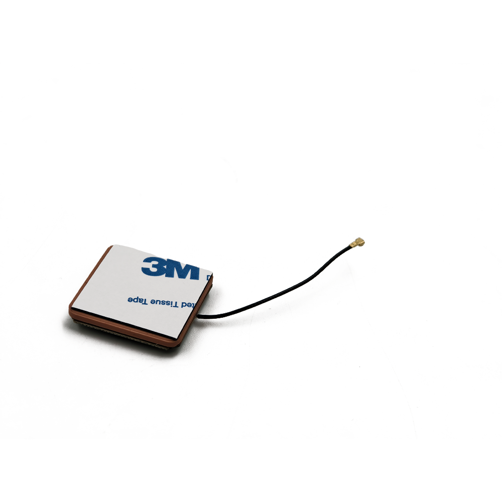
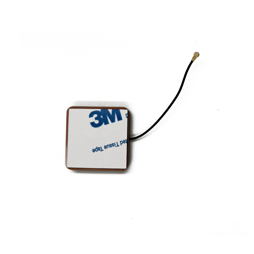
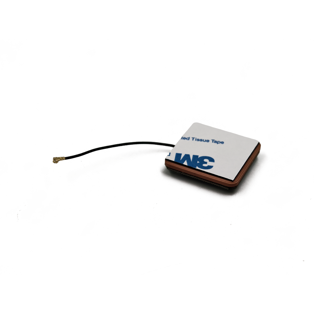
The "Ceramic Patch" refers to the core radiating element. A patch antenna is a type of resonant antenna where a sheet of metal (the patch) is mounted over a larger sheet of metal (the ground plane), separated by a dielectric substrate. The choice of a ceramic material with a high dielectric constant (often denoted as εr, values typically ranging from 20 to 90) is a pivotal design decision. This high εr allows the electromagnetic waves to be effectively "slowed down" within the substrate. The key benefit is a drastic reduction in the physical size of the antenna. The resonant frequency of a patch antenna is inversely proportional to the square root of the dielectric constant (f ~ 1/√εr). Therefore, for a given frequency (like the GNSS L1 band at 1575.42 MHz), a high εr material enables a much smaller patch size compared to a conventional substrate like FR4 (εr ~4.3).
However, this miniaturization comes with a complex set of engineering trade-offs. While a high dielectric constant is excellent for reducing size, it also typically reduces the operational bandwidth and radiation efficiency, and makes the antenna's performance more sensitive to manufacturing tolerances and temperature changes. Therefore, designing a high-performance RTK antenna using such materials is a delicate balancing act, requiring advanced electromagnetic simulation, precise material science, and meticulous manufacturing control.
In essence, this antenna is the product of a demanding quest for precision, stability, and miniaturization. It is the unsung hero of high-precision GNSS, quietly and reliably capturing the faint whispers from satellites thousands of kilometers away, and doing so in a form factor that can be integrated into drones, agricultural machinery, autonomous robots, and survey equipment, thereby powering the revolution in geospatial accuracy.
The design and construction of an RTK-grade ceramic patch antenna are a meticulous process that blends materials science, electromagnetic theory, and precision engineering. Every layer and material is chosen to optimize performance for the stringent requirements of carrier-phase measurement.
1. The Ceramic Substrate:
The heart of the antenna is the ceramic puck itself. Materials like Barium Strontium Titanate, Titanates, or other proprietary ceramic composites are used. Their dielectric constants can range from 20 for a balance of size and performance, up to 90 or higher for ultra-miniaturized designs.
Material Purity and Homogeneity: The ceramic must be exceptionally pure and homogeneous. Any voids, impurities, or inconsistent density within the material will create local variations in εr, distorting the electromagnetic fields and destabilizing the phase center.
Temperature Stability: The dielectric constant of all materials changes with temperature. For RTK, a low Temperature Coefficient of Dielectric Constant (TCε) is paramount. Premium ceramics are engineered to have a TCε very close to zero (e.g., ±5 ppm/°C) to ensure the antenna's resonant frequency and phase characteristics remain stable across a wide operating temperature range (-40°C to +85°C).
2. The Radiating Patch:
The patch itself is a thin layer of highly conductive material, typically silver or copper, screen-printed or fired onto the top surface of the ceramic puck. The shape is almost always square or circular, as these shapes support the fundamental resonant mode (TM₁₀) needed for GNSS reception. The precise dimensions of the patch—calculated using complex formulas involving the dielectric constant and the desired frequency—determine the resonant frequency.
3. The Feed Mechanism:
How power is delivered to the patch is critical. Two common methods are used:
Probe Feed: A coaxial cable's inner conductor is soldered directly to a point on the patch through a hole drilled in the ceramic and ground plane. The location of this feed point controls the input impedance (typically 50Ω).
Aperture-Coupled Feed: A more advanced technique where the patch is electromagnetically coupled to a microstrip feed line located on a separate substrate layer beneath the ground plane. A slot in the ground plane allows this coupling. This method isolates the radiating element from the feed network, often resulting in better bandwidth and spurious radiation suppression.
4. The Ground Plane:
Beneath the ceramic substrate lies a continuous, unbroken ground plane. This is non-negotiable for an RTK antenna. Its primary functions are:
Defining Radiation Pattern: It forces the antenna to radiate in a directional, hemispherical pattern upwards towards the sky, which is ideal for receiving satellite signals.
Multipath Rejection: It acts as a shield, blocking low-angle signals that are likely to be multipath reflections from the ground or nearby objects. A larger ground plane generally provides better multipath rejection.
Phase Center Stability: A stable, symmetrical ground plane is essential for maintaining a consistent phase center.
5. The Low-Noise Amplifier (LNA):
Located immediately after the radiating element, often within the antenna housing, is the LNA. Its job is to amplify the extremely weak satellite signals (around -130 dBm) before any significant loss occurs in the transmission cable. A high-gain (30-40 dB), ultra-low-noise-figure (<1.5 dB) LNA is standard. It is often powered through the same coaxial cable via bias-tee circuitry.
6. The Radome and Housing:
The entire assembly is encapsulated in a protective radome. The material must be radio-transparent at GNSS frequencies. Its shape is also engineered—a dome (dome-type antenna) is common as it helps minimize the accumulation of water and snow, which can detune the antenna. The base often contains a magnetic mount or a standard threaded insert (5/8"-11) for secure mounting.
The construction process involves precise sintering of the ceramic, accurate screen printing, and careful assembly to ensure perfect alignment and sealing (often to IP67 standards). The result is a robust, weatherproof, and highly precise electromagnetic sensor.
The working principle of a ceramic patch antenna is based on resonant cavity theory, but its function within an RTK system is defined by its ability to faithfully preserve the phase of incoming satellite signals.
1. Resonance and Radiation:
The ceramic patch antenna operates as a resonant cavity. The patch and the ground plane form two conducting walls, and the ceramic substrate forms the dielectric medium. When excited by the feed, electromagnetic fields are set up within this cavity. The dimensions of the patch are designed so that it resonates at the target GNSS frequencies (e.g., L1: 1575.42 MHz, L2: 1227.60 MHz). At resonance, the antenna efficiently converts electrical energy from the feed into electromagnetic waves radiating into space (for transmission) or vice versa (for reception). The high dielectric constant confines most of the field within the ceramic, which is why the antenna can be so small.
2. Reception of GNSS Signals:
As right-hand circularly polarized (RHCP) waves from GNSS satellites travel over 20,000 km and impinge upon the antenna, they induce tiny currents on the patch. The antenna's structure is designed to be sensitive primarily to RHCP, which helps reject reflected signals (which often reverse their polarization to LHCP) and thus mitigates multipath error. The captured signal energy is transferred via the feed to the LNA.
3. The Critical Role of Phase Center:
For standard navigation, the antenna's amplitude response (gain pattern) is most important. For RTK, the phase response is everything. The Phase Center is the hypothetical point in space from which the transmitted or received electromagnetic radiation appears to originate. In an ideal antenna, this point would be a fixed physical location that does not move regardless of the direction (azimuth and elevation) of the satellite.
Phase Center Offset (PCO): In a real antenna, the phase center is not perfectly aligned with the physical center. This PCO must be precisely measured and calibrated by the manufacturer.
Phase Center Variation (PCV): More critically, the apparent phase center can move slightly as the angle of the incoming signal changes. This PCV is a primary source of error for RTK. A high-quality ceramic patch antenna is meticulously designed to have minimal PCV—often less than 1-2 mm across the entire hemisphere. This stability is what allows the RTK receiver to make precise comparisons of the carrier phase measurements from different satellites.
4. Integration with the RTK System:
The antenna's role is to provide the RTK receiver with the cleanest possible raw signal. The receiver then performs the complex task of:
Tracking the phase of the carrier wave for each satellite.
Receiving correction data from a base station (via a separate link).
Using double-differencing algorithms to cancel out common errors (satellite and receiver clocks, atmospheric delays).
Resolving the integer wavelength ambiguity.
The antenna's low noise, stable phase center, and strong multipath rejection directly determine how quickly and reliably the receiver can achieve a "fixed" integer solution, which is the key to centimeter accuracy.
In summary, the antenna doesn't process data; it is the faithful guardian of the signal's integrity. Its primary job is to capture the phase of the electromagnetic wave with microscopic consistency, providing the raw, high-quality data that the RTK engine requires to perform its precision calculations.
The unique blend of precision, miniaturization, and robustness makes the RTK ceramic patch antenna the sensor of choice for a vast and growing range of applications that depend on centimeter-accurate positioning.
Applications:
Precision Agriculture: Embedded into autonomous tractors, harvesters, and sprayers for guidance with centimeter accuracy, enabling practices like controlled traffic farming, variable rate application, and yield mapping. Their small size allows for low-profile mounting.
Unmanned Aerial Systems (UAS/Drones): Essential for drone-based photogrammetry, LiDAR mapping, and surveying. The antenna provides the precise geotag for each captured image, enabling the creation of highly accurate 2D and 3D models without the need for numerous ground control points. Their light weight and small form factor are critical for flight time and payload.
Autonomous Ground Vehicles: From last-mile delivery robots and warehouse logistics robots to large-scale autonomous mining trucks and agricultural rovers. These systems use RTK as a primary source of absolute localization, correlating their precise position with pre-mapped environments.
Machine Control and Construction: Mounted on bulldozers, graders, and excavators for grade control systems. The antenna allows the machine to follow a 3D digital design plan automatically, increasing efficiency and reducing material waste and rework.
Geomatics and Surveying: Used on handheld data collectors, backpack systems, and portable base stations for high-accuracy GIS data collection, cadastral surveying, and engineering layout. Their ruggedness is key for field use.
Emerging Technologies: Found in systems for precision landing of UAVs, augmented reality (AR) for overlaying digital information onto the physical world with precise alignment, and scientific monitoring (e.g., crustal deformation studies).
Future Trends:
Multi-Band, Multi-Constellation as Standard: The future is full-band: L1, L2, L5 for all major constellations (GPS, Galileo, GLONASS, BeiDou). Antennas will evolve from single-layer patches to complex, stacked, or fragmented designs to cover this enormous bandwidth without sacrificing performance, enabling faster and more reliable RTK fixes everywhere.
Tighter Integration with IMU and Receivers: The trend is toward "all-in-one" positioning modules. The antenna, RTK receiver, and an Inertial Measurement Unit (IMU) will be packaged together into a single, tightly coupled unit. This allows the IMU to provide high-rate position and attitude data during short GNSS outages (e.g., under trees or bridges), with the antenna providing the absolute calibration point.
Enhanced Multipath Mitigation: Advanced techniques like controlled reception pattern antennas (CRPAs) or adaptive null-steering, once exclusive to military systems, will trickle down to high-end commercial RTK antennas. Using multiple patch elements, these antennas can actively null out interfering or multipath signals.
AI-Optimized Design and Operation: Machine learning and AI will be used in two ways: first, to optimize the electromagnetic design of the patches themselves in simulation software, and second, embedded within the system to intelligently identify and filter out multipath or interference in real-time based on the signal environment.
Material Science Advancements: Research into new ceramic composites and meta-materials will continue, aiming to achieve even higher dielectric constants with near-zero loss tangents and perfect temperature stability, pushing the boundaries of miniaturization and performance further.
Mass Market Adoption: As costs gradually decrease, this high-precision technology will move into consumer and automotive applications, such as advanced driver-assistance systems (ADAS), vehicle-to-everything (V2X) communication, and personal navigation for the visually impaired.
Conclusion
The RTK Ceramic Patch Antenna with a High Dielectric Constant is a masterpiece of engineering that sits at the vital intersection of materials science, electromagnetic theory, and practical application needs. It is far more than a simple passive component; it is a precision sensor whose performance fundamentally dictates the capabilities of the entire high-precision positioning system it serves.
Its development has been driven by the conflicting demands of the market: the need for ever-greater accuracy, which requires electrical stability and size, and the need for miniaturization and ruggedness for integration into mobile and autonomous platforms. The choice of a high dielectric constant ceramic is the key enabler that resolves this conflict, allowing for a radical reduction in size while maintaining the critical characteristics of phase center stability and multipath rejection that are the bedrock of RTK.
While this choice introduces significant challenges—primarily limited bandwidth, design complexity, and cost—these are not insurmountable barriers. They are instead design parameters that are actively managed and overcome through continuous innovation in materials, feed techniques, and manufacturing processes. The resulting component is indispensable across a vast spectrum of industries, from agriculture to robotics, that are being transformed by autonomy and data-driven operation.
Looking forward, the evolution of this antenna is tightly coupled with the future of autonomy itself. As systems demand faster, more reliable, and more ubiquitous centimeter-level accuracy, the antenna will continue to evolve, becoming more integrated, more intelligent, and more capable. It will transition from a specialized component to a core enabling technology for the intelligent, connected, and automated world, silently and precisely anchoring our digital creations to the physical Earth.

 86 0755 2819 9597
Lucy Yang | lucy.y@toxutech.com
Nicole Li | nicole@toxutech.com
Dotty Zhao | sales04@toxutech.com
Global Business Director / Sales Team / Global Operations


 En
En Cn
Cn Korean
 Home >


