

-
Products -PCBA Manufacturing RF Connectors RF Cable Assemblys Embedded Antennas External Antennas Positioning Chips and Modules
RF Connectors

RF Cable Assemblys
Embedded Antennas
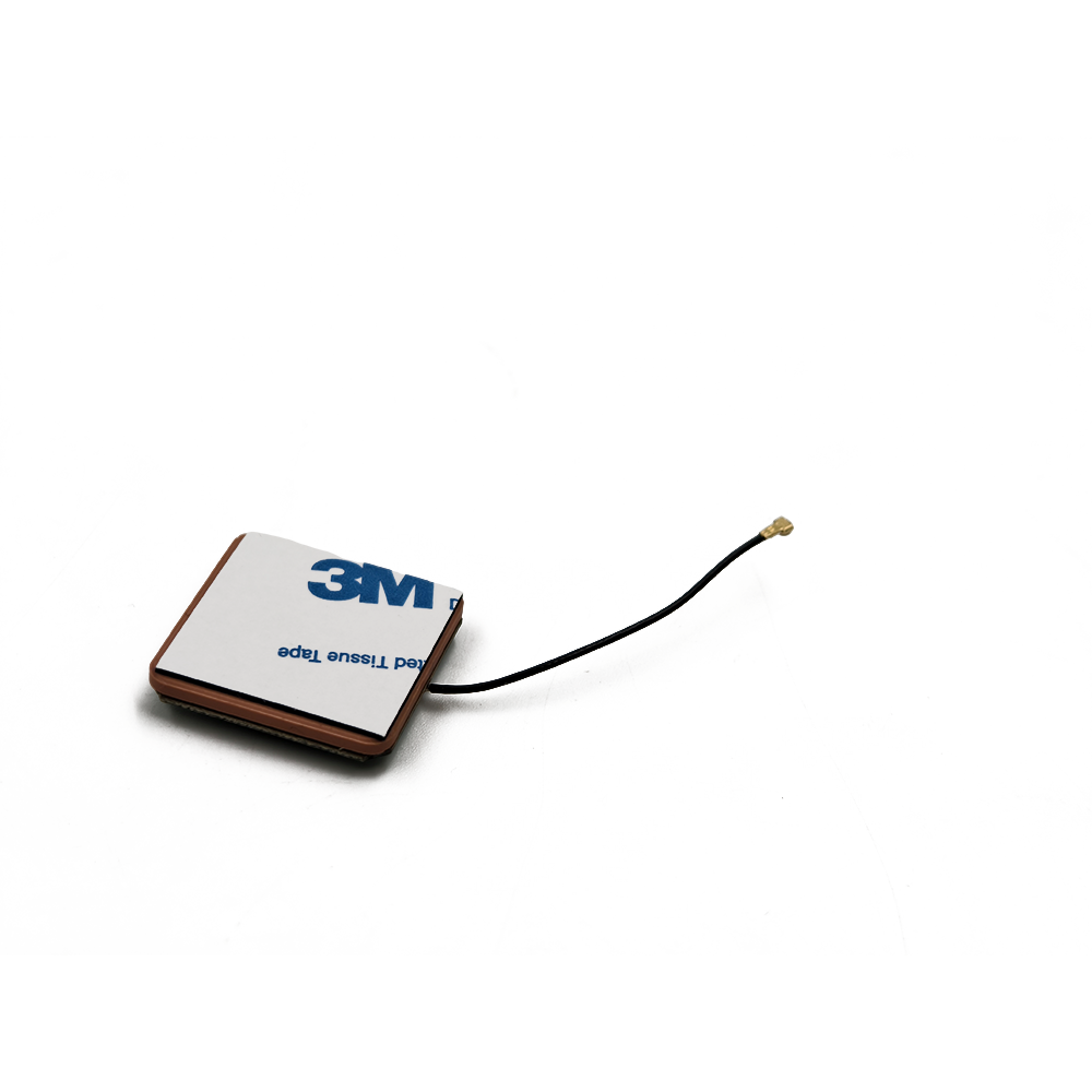
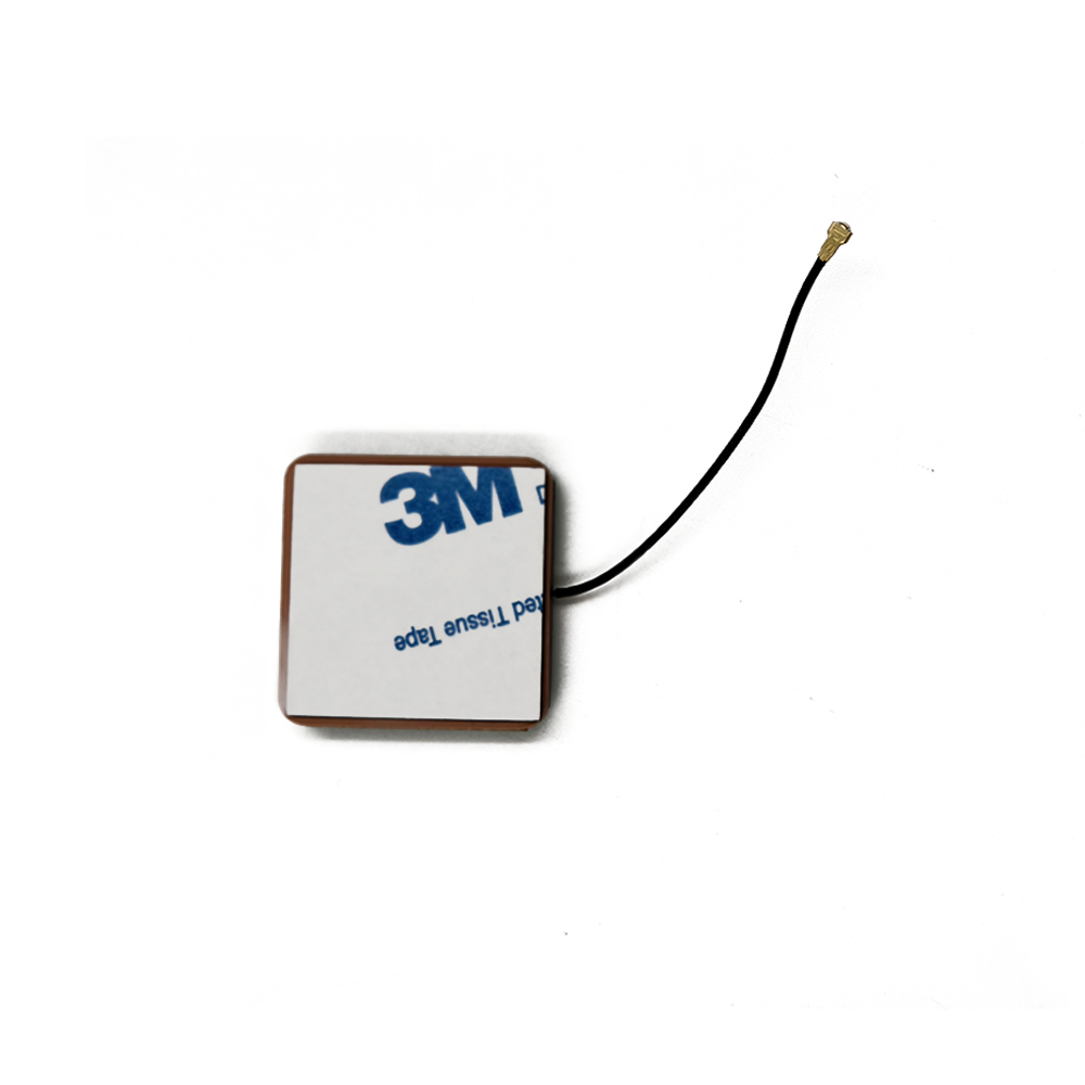
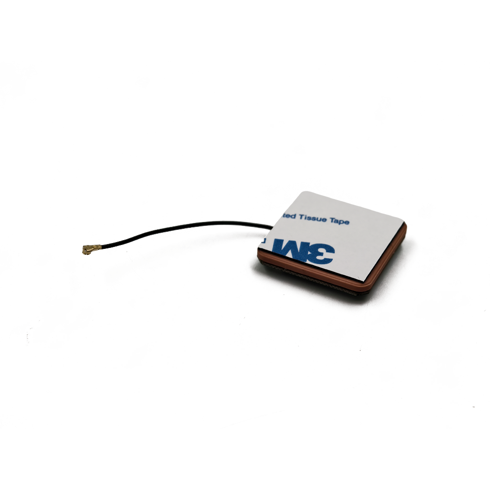
External Antennas
Positioning Chips and Modules


 Language


Language


The advent of high-precision positioning technology has revolutionized numerous industries, from agriculture and construction to robotics and surveying. At the heart of this revolution lies Real-Time Kinematic (RTK) technology, a technique that enhances the precision of position data derived from satellite-based positioning systems (like GPS, GLONASS, Galileo, and BeiDou) from meter-level accuracy to centimeter-level. However, this remarkable feat of engineering is critically dependent on one often-overlooked component: the antenna. Not just any antenna, but a specialized, high-performance antenna designed to meet the exacting demands of RTK—the Ceramic Patch Antenna.
An RTK Ceramic Patch Antenna is a type of passive microstrip antenna specifically engineered to receive satellite signals with extreme phase stability, low multipath rejection, and high gain. Its primary role is to act as the first and most crucial interface in the RTK signal chain. It captures the faint electromagnetic waves transmitted from satellites orbiting over 20,000 kilometers away and converts them into electrical signals for the RTK receiver to process. The performance of this antenna directly dictates the quality of the raw data, which in turn is fundamental to achieving and maintaining a fixed, centimeter-accurate RTK solution.
To understand its importance, one must first grasp the basic principle of RTK. Standard GNSS (Global Navigation Satellite System) positioning uses the code information from satellite signals, which is inherently coarse. RTK, in contrast, uses the carrier phase of the signal, which has a much shorter wavelength (e.g., ~19 cm for the GPS L1 frequency). By resolving the integer ambiguity of the number of carrier waves between the satellite and the receiver, RTK can measure the distance with millimeter-level precision. However, this phase measurement is incredibly susceptible to errors. Any perturbation in the signal's path, such as reflection (multipath), attenuation, or phase noise introduced by the antenna itself, can corrupt the measurement and prevent the integer ambiguity from being resolved, causing the receiver to remain in a "float" solution with degraded accuracy.
The ceramic patch antenna is designed to mitigate these errors from the very moment the signal is captured. The term "patch" refers to its physical structure: a flat, rectangular or circular radiating element (the patch) etched onto a dielectric substrate, which is then mounted over a ground plane. The "ceramic" part denotes the material of the substrate, which is a key differentiator. Unlike antennas built on cheaper substrates like FR4, ceramic offers a high dielectric constant (εr). This property allows the antenna to be electrically small—meaning its physical size is a fraction of the wavelength it's designed to receive—while maintaining effective performance. This miniaturization is essential for integrating high-precision GNSS into compact devices like drones, smartphones, and autonomous vehicle modules.
The core function of an RTK-grade antenna transcends mere signal reception. It must perform several specialized tasks:
1. Multi-Band and Multi-Constellation Support: Modern RTK requires tracking multiple frequencies (e.g., GPS L1/L2/L5, Galileo E1/E5a/E5b/E6) from multiple satellite constellations. This diversity provides more satellites in view, leading to faster convergence times and more robust solutions, especially in challenging environments. A high-end RTK ceramic antenna is designed with stacked patches or other techniques to resonate efficiently across these different bands.
2. Phase Center Stability: This is arguably the most critical characteristic. The phase center is the point from which the radiation seems to emanate. For RTK, this point must be stable and consistent across different frequencies, angles of arrival (azimuth and elevation), and over time. Any movement of the phase center with the satellite's position in the sky introduces a measurable error that the RTK engine cannot easily distinguish from a real change in position. Premium RTK antennas have a well-defined and stable phase center that is meticulously calibrated.
3. Multipath Rejection: Multipath occurs when a satellite signal reflects off surfaces like the ground, buildings, or water before reaching the antenna. This reflected signal arrives later than the direct line-of-sight signal, creating destructive interference and phase errors. RTK ceramic patch antennas are designed with a ground plane and specific patch geometry to have a sharp, right-hand circularly polarized (RHCP) radiation pattern that is receptive to signals from above (direct path) and attenuated towards the horizon (where multipath typically originates).
4. High Gain and Low Noise: The antenna must provide sufficient gain to amplify weak satellite signals to a level usable by the receiver's low-noise amplifier (LNA), which is often integrated directly into the antenna assembly. Simultaneously, it must introduce minimal self-generated noise to preserve the signal-to-noise ratio (SNR).
In summary, the RTK ceramic patch antenna is not a commodity component but a precision instrument. It is the gatekeeper of signal integrity, enabling the sophisticated algorithms of RTK to function. Its development represents a convergence of materials science, electromagnetic theory, and precision manufacturing, all aimed at the singular goal of extracting the purest possible phase information from satellite signals to unlock centimeter-accurate positioning for the modern world.
The design and construction of an RTK ceramic patch antenna is a meticulous process that balances electromagnetic performance, physical robustness, and manufacturability. Every layer and material choice is a calculated decision to optimize the key parameters of phase center stability, bandwidth, gain, and multipath rejection. The architecture is a sophisticated layered structure, far more complex than a simple piece of metal on ceramic.
1. Core Material: The Ceramic Substrate
The foundation of the antenna is the ceramic substrate. The choice of ceramic is paramount. Common materials include alumina (Al₂O₃), barium tetratitanate, and other proprietary ceramic blends. The primary reason for using ceramic is its high dielectric constant (εr), which typically ranges from 9 to 40 or higher. A high εr reduces the wavelength within the material, allowing the radiating patch to be physically smaller for a given frequency. This is crucial for consumer and industrial devices where space is at a premium. However, a very high εr also leads to narrower bandwidth and higher losses. Therefore, antenna designers must strike a balance between miniaturization and performance, often opting for ceramics with εr in the 20-30 range for a good compromise.
The ceramic must also have a very low loss tangent (tan δ). This property quantifies the signal energy lost as heat within the dielectric material itself. A low loss tangent (e.g., < 0.002) is essential for maintaining high efficiency and gain, ensuring that the faint satellite signals are not further weakened before they even reach the receiver.
2. The Radiating Patch
The patch itself is a conductive material, almost always copper, which is deposited onto the top surface of the ceramic substrate using a process like screen printing, plating, or sputtering. The shape is typically square or circular, as these geometries support well-understood resonant modes (TM₁₀ mode for rectangular patches). The precise dimensions of the patch—its length (L), width (W), and the location of the feed point—determine its resonant frequency, impedance, and bandwidth.
For a single-band antenna, the length L is approximately half the wavelength in the dielectric (λ_d), calculated as λ_d = λ_0 / √εr, where λ_0 is the free-space wavelength. To achieve multi-band operation (e.g., L1 and L2 GPS bands), designers use several techniques:
Stacked Patches: This is the most common method for high-performance RTK antennas. A second, larger patch is printed on a separate ceramic layer placed above the primary patch. The lower patch is tuned to the higher frequency (e.g., L1 at 1575.42 MHz), and the upper patch acts as a parasitic element, coupled to the first and resonant at the lower frequency (e.g., L2 at 1227.60 MHz). This allows for independent optimization of each band.
Slotted Patches: Inserting slots of specific shapes and sizes into the patch can perturb the current distribution and create multiple resonant paths.
Multi-Feed Points: Using separate feed points for different frequencies on a single, specially shaped patch.
3. The Feed Mechanism
How power is transferred between the antenna and the receiver cable is critical. The two main techniques are:
Probe Feeding: A small pin (probe) is soldered to the patch and passes through a hole drilled in the substrate and ground plane to connect to the coaxial cable underneath. This is a robust method but can introduce unwanted inductance.
Aperture-Coupled Feeding: This more advanced technique de-couples the radiating element from the feed network. The patch is on the top layer. The energy is coupled from a microstrip feedline on a bottom layer through a slot etched in the intermediate ground plane. This allows for better optimization of bandwidth and isolation between the radiation and feed structures.
4. The Ground Plane
A continuous, unbroken conductive ground plane is essential beneath the substrate. It serves two vital functions: it acts as a reflector to direct the antenna's radiation pattern upwards (providing a hemispherical view of the sky), and it is the primary tool for suppressing multipath. A larger ground plane generally improves the gain pattern and multipath rejection at low elevation angles. The edge of the ground plane can be shaped or corrugated to further suppress surface waves and minimize backward radiation.
5. Integrated Low-Noise Amplifier (LNA)
While the antenna itself is passive, virtually all RTK ceramic patch antennas are packaged as an "active antenna." This means a Low-Noise Amplifier (LNA) is integrated directly into the antenna housing, immediately after the radiating element. The LNA's job is to amplify the extremely weak signals (often below -130 dBm) captured by the patch to a level strong enough to travel through the coaxial cable to the receiver without being degraded by cable loss and noise. The LNA must have very high gain (e.g., 25-40 dB) and an exceptionally low noise figure (NF < 1 dB is common). This active component requires power, which is typically supplied to the antenna through the same coaxial cable via a DC bias voltage (a system called "bias-T").
6. Housing and Environmental Protection
The entire assembly—ceramic element, ground plane, and LNA—is encased in a protective housing. This housing is made from materials that are radio-transparent at GNSS frequencies, typically plastic (like ABS) or polycarbonate. The housing is designed to be weatherproof (often rated to IP67) to protect the electronics from moisture, dust, and chemicals. Furthermore, the radome's shape and material are part of the electromagnetic design; they must not detune the antenna or introduce additional phase delays.
Finally, the entire antenna undergoes rigorous calibration. Using an anechoic chamber and a precisely positioned reference antenna, the phase center variation (PCV) of the antenna is measured across all angles of arrival and for all frequencies. This PCV table is then provided to the end-user and can be applied within the RTK processing software to correct for these inherent antenna-induced errors, pushing the final accuracy even closer to the theoretical limit. This meticulous design and construction process transforms a simple concept—a patch on ceramic—into a high-precision sensor capable of enabling centimeter-accurate global navigation.
The working principle of an RTK ceramic patch antenna can be understood by dissecting its operation through the lens of fundamental antenna theory, its role in the RF chain, and, most importantly, its contribution to the phase-based measurement at the core of RTK. It functions as a transducer, but its performance is judged by the purity and stability of the phase information it delivers.
Fundamental Resonance: The Microstrip Patch Antenna
At its most basic, a patch antenna is a resonant cavity. The patch conductor and the ground plane form the two walls of a very low-profile cavity filled with the ceramic dielectric. The length `L` of the patch is slightly less than half the wavelength in the dielectric material (λ_d/2) due to fringing fields at the edges. When excited by a feed at the correct location, this cavity resonates, and electromagnetic fields are set up between the patch and the ground plane. The fringing fields at the radiating edges (the two edges parallel to the length `L`) curl around and combine to produce radiation that is predominantly polarized perpendicular to the patch's surface. However, for GNSS signals, which use circular polarization, this linear polarization is inadequate.
Achieving Circular Polarization (RHCP)
Satellite signals are transmitted using Right-Hand Circular Polarization (RHCP). This means the electric field vector of the signal rotates clockwise as it travels towards the receiver. RHCP is used because it is less affected by Faraday rotation when passing through the ionosphere and helps to mitigate certain multipath effects. To receive this signal efficiently, the antenna must also be RHCP.
A simple square patch excited at a single point produces linear polarization. To transform this into circular polarization, the patch must be excited by two feed points with signals that are equal in amplitude but 90 degrees out of phase (a quadrature phase shift). This creates two orthogonal resonant modes (TM₁₀ and TM₀₁). The superposition of these two modes, if designed correctly, results in a rotating electric field vector—circular polarization. This is typically achieved by:
Single Feed with a Perturbation: A small notch or tab is cut into the corner of the patch, or the feed point is placed slightly off-center. This perturbs the geometry and creates two degenerate modes with a 90-degree phase shift.
Dual Feed with a Hybrid Coupler: A more precise method uses two separate feed points connected to a external 90-degree hybrid coupler circuit. This ensures perfect amplitude and phase balance, resulting in very pure circular polarization and a high Axial Ratio (a measure of circularity; lower is better). This method is more complex and expensive but is standard for high-precision RTK antennas.
The Radiation Pattern: The "View" of the Sky
The antenna's radiation pattern is a 3D map of its gain in different directions. The RTK ceramic patch antenna is designed to have a specific and desirable pattern:
Hemispherical Coverage: Maximum gain is directed towards the zenith (straight up), with gain gradually decreasing towards the horizon. This is ideal for viewing satellites, which are always above the horizon.
Front-to-Back Ratio: The gain towards the sky (front) is maximized, while the gain downwards (backlobe) is minimized. This is achieved by the ground plane, which acts as a shield.
Low Elevation Roll-Off: The gain drops off sharply at angles below 5-10 degrees above the horizon. This is a crucial feature for multipath rejection, as signals reflecting off the ground or buildings arrive at these low angles. By being less sensitive here, the antenna naturally attenuates these harmful reflected signals.
The Phase Center: The Heart of RTK Performance
The Phase Center is the conceptual point in space from which the antenna appears to be radiating. For an ideal antenna, this would be a single, fixed point in space. In reality, it is a region, and its apparent location can shift depending on the frequency and the direction (elevation and azimuth) from which the signal is arriving. This movement is called Phase Center Variation (PCV).
For RTK, PCV is a direct source of error. If the phase center moves when a satellite moves across the sky, the receiver interprets this as a change in the distance to the satellite, introducing a positioning error. The paramount goal of RTK antenna design is to create a phase center that is:
1. Stable: Its location moves minimally with the angle of arrival.
2. Consistent: Its behavior is identical across all frequencies (L1, L2, L5).
3. Predictable: Its variations can be accurately measured and modeled.
The symmetric design of the patch, the high-quality ceramic substrate, and the precision of the feed mechanism all contribute to a stable phase center. The phase center is not a physical point you can see; it is determined through precise calibration in an anechoic chamber.
The Active Element: The Low-Noise Amplifier (LNA)
The passive antenna element captures the signal. The integrated LNA then performs the first critical active function. Its primary characteristics are:
Gain: It provides high amplification (e.g., 30 dB) to overcome subsequent losses in the cable connecting the antenna to the receiver.
Low Noise Figure (NF): It adds the absolute minimum amount of self-generated noise to the signal. Any noise added here is amplified along with the signal and directly degrades the Signal-to-Noise Ratio (SNR), which the receiver needs for tracking weak signals and making precise phase measurements.
Linearity: It must remain linear across a wide dynamic range to avoid distorting the signal when strong nearby signals (e.g., from cell phones) are present, which could cause intermodulation products that jam the GNSS receiver.
The Complete Signal Journey
1. A RHCP electromagnetic wave from a satellite impinges upon the ceramic patch antenna.
2. The patch resonates, and the fringing fields induce a small current on the patch element.
3. The feed mechanism transfers this RF current.
4. The current, representing the extremely weak signal, is immediately amplified by the integrated LNA with minimal added noise.
5. The now-amplified signal travels down the coaxial cable to the RTK receiver.
6. The receiver digitizes the signal and performs correlation and phase measurement.
7. The receiver's processor, using RTK algorithms, compares the phase measurements from this rover antenna with those from a base station antenna. The stability of the phase center in both antennas is critical for this comparison to yield a correct integer ambiguity resolution, leading to a centimeter-accurate fix.
In essence, the working principle of the RTK antenna is to act as a stable, high-fidelity, and selective collector of microwave radiation, preserving the integrity of the carrier phase information from the moment it arrives from space until it is delivered to the receiver's digital processing unit.
RTK ceramic patch antennas have become the de facto standard for high-precision applications for a compelling set of reasons. However, achieving this performance is not without its engineering and economic challenges. Understanding these trade-offs is essential for selecting the right antenna for a given application.
Advantages
1. Exceptional Phase Center Stability: This is their single greatest advantage. The symmetric and rigid nature of the ceramic patch structure, combined with advanced feed techniques, results in a highly stable and well-defined phase center. This minimizes measurement errors that are directly interpreted as position errors in the RTK engine, making fast and reliable integer ambiguity resolution possible. This stability is far superior to that of cheaper helical or planar antennas on FR4 substrates.
2. Effective Multipath Rejection: The combination of the ground plane and the carefully engineered radiation pattern provides inherent rejection of low-elevation signals, which are typically the reflected multipath signals. Their high front-to-back ratio further ensures that signals from below the antenna (another source of multipath) are strongly attenuated. This clean signal acquisition is a prerequisite for high-precision work in urban canyons or near reflective surfaces.
3. Compact Form Factor and Ruggedness: The high dielectric constant of ceramic allows for significant miniaturization. An antenna for the GPS L1 band (19 cm wavelength) can be made smaller than a 25mm x 25mm square. This small, flat profile is ideal for integration into portable devices, drones, and automotive systems. Furthermore, the ceramic substrate is mechanically rigid, thermally stable, and resistant to environmental factors like humidity, making the entire assembly very robust.
4. Multi-Band/Multi-Constellation Capability: Through techniques like stacked patches, a single, compact antenna unit can be designed to resonate efficiently across all major GNSS bands (L1, L2, L5, E1, E5, E6, B1, B2, B3). This future-proofs devices and allows them to leverage all available satellites for faster convergence, higher accuracy, and improved reliability.
5. High Efficiency and Low Loss: Premium ceramic materials have a very low loss tangent, meaning most of the received signal energy is transferred to the receiver rather than being dissipated as heat within the antenna itself. This high radiation efficiency is crucial for maintaining a strong Signal-to-Noise Ratio (SNR), which is directly linked to tracking performance and accuracy.
6. Consistent Mass Production: While the design is complex, the manufacturing process (screen printing, sintering) is well-suited for high-volume production. This allows for consistent performance from one antenna to the next, which is vital for applications where a base and rover antenna must be matched or for OEMs integrating them into thousands of devices.
Challenges and Limitations
1. Inherently Narrow Bandwidth: A fundamental trade-off of using a high-dielectric-constant substrate is that it reduces the operational bandwidth of the antenna. While a patch antenna on a low-εr substrate might have a bandwidth of several hundred MHz, a ceramic patch's native bandwidth can be very narrow. This is a major challenge when designing for multiple bands that are widely separated in frequency (e.g., L1 at 1575 MHz and L2 at 1227 MHz). Engineers must employ advanced techniques like stacked patches, which add complexity and cost, to overcome this limitation.
2. Cost: The raw materials—high-purity, precisely engineered ceramic powders—are more expensive than standard PCB substrates like FR4. The manufacturing process involves high-temperature sintering and precision metallization, which is more capital-intensive than standard PCB etching. The integration of a high-quality, low-noise LNA and the necessary filtering adds further cost. Consequently, a high-performance RTK active antenna can cost orders of magnitude more than a standard GNSS antenna.
3. Thermal Sensitivity: While ceramic is thermally stable, its dielectric constant does change with temperature (a property known as its temperature coefficient). This thermal drift causes the resonant frequency of the patch to shift slightly. For less demanding applications, this is negligible. For high-end RTK, this can introduce small but measurable phase center movements and impedance mismatches. To mitigate this, manufacturers may use temperature-compensated ceramic blends or implement advanced designs that are less sensitive to these changes, again adding to the cost.
4. Design Complexity: Designing a high-performance, multi-band patch antenna is a non-trivial task that requires sophisticated electromagnetic simulation software (e.g., HFSS, CST) and significant expertise. Optimizing the parameters for performance across multiple bands, achieving a good axial ratio (pure circular polarization), and maintaining a stable phase center is an iterative and computationally intensive process.
5. Calibration Requirement: To achieve the highest possible accuracy, the phase center variations of the antenna must be precisely mapped for all frequencies and all angles of arrival. This requires expensive anechoic chamber testing and specialized calibration services. While this is standard practice for geodetic-grade antennas, it adds time and expense to the development and manufacturing process. Without this calibration and the application of its corrections in the RTK software, the antenna's inherent PCV will limit the ultimate accuracy.
6. Integration Considerations: The antenna's performance is not isolated. Its radiation pattern and impedance can be detuned by its proximity to other components (e.g., metal casings, batteries, displays) in the end device. OEMs must carefully follow integration guidelines provided by the antenna manufacturer regarding ground plane size, keep-out areas, and housing materials to ensure the antenna performs as specified. This can constrain industrial design.
In conclusion, the advantages of RTK ceramic patch antennas—primarily their phase stability and multipath rejection—make them indispensable for centimeter-accurate positioning. The challenges, largely centered around bandwidth, cost, and thermal management, are the driving forces behind ongoing research and development in the field, pushing the technology towards wider bandwidths, lower costs, and even greater stability.
The unique capabilities of RTK ceramic patch antennas have enabled a paradigm shift across a diverse range of industries where precision, automation, and efficiency are paramount. Their application is moving from specialized niches into mainstream technology, a trend that is accelerating rapidly.
Applications
1. Precision Agriculture: This is one of the largest and most established markets. RTK-guided tractors and harvesters can drive with 2-3 cm accuracy, enabling automated operations like planting, fertilizing, and harvesting. This eliminates overlaps and gaps, optimizing seed, fertilizer, and pesticide use, which boosts yields and reduces costs and environmental impact. Drones equipped with RTK are used for high-accuracy field mapping and targeted spraying.
2. Surveying, Mapping, and Construction: Surveyors use RTK rovers with ceramic patch antennas to precisely mark points and map topography without the need for traditional stakes and tapes. In construction, RTK guides bulldozers, graders, and pile drivers ("machine control"), ensuring earth is moved and foundations are built exactly to the digital design model (BIM), drastically reducing rework and saving time.
3. Unmanned Aerial Vehicles (Drones) and Aerial Mapping: Drones for mapping and LiDAR scanning require precise positioning not just for navigation but, more importantly, for geotagging each captured image or laser point. An RTK system provides the precise camera/laser position and, crucially, the orientation of the drone, enabling the creation of highly accurate 2D orthomosaics and 3D models without the need for numerous ground control points.
4. Autonomous Vehicles and Robotics: While full autonomy is complex, RTK provides a crucial absolute positioning layer for self-driving cars, autonomous mobile robots in warehouses, and agricultural robots. It allows these systems to know their exact location in the world, which is then fused with data from cameras, LiDAR, and inertial sensors for navigation and obstacle avoidance. The stability of the ceramic patch antenna is critical for safety-critical applications.
5. Marine and Hydrography: RTK is used for precision docking of large vessels, dynamic positioning of research and construction ships, and for conducting accurate hydrographic surveys to map seafloors and riverbeds.
6. Emerging Consumer and IoT Applications: As the technology becomes smaller and more affordable, it is trickling into consumer devices. Smartphones are now incorporating dual-frequency GNSS receivers, and high-end models are beginning to feature RTK capabilities for improved location-based services, augmented reality (AR) that stays locked to the real world, and precise personal mobility applications.
Future Trends
The evolution of RTK ceramic patch antennas is focused on overcoming current challenges and expanding into new applications. Key trends include:
1. Miniaturization and Integration: The push for ever-smaller devices will continue. This involves developing ceramics with even higher dielectric constants to allow for smaller patches, and more advanced techniques like embedding the antenna within the device's PCB or housing itself, making it virtually invisible. Integration with other RF systems (e.g., cellular, WiFi) into a single package is also a key research area.
2. Wider Bandwidth and Multi-Band Operation: The number of GNSS signals and satellites is constantly increasing. Future antennas will need to support more bands (e.g., new L-band navigation signals) with even wider instantaneous bandwidth. This will require innovations in patch design, new ceramic materials with tailored properties, and potentially the move to magneto-dielectric substrates.
3. "Superior" and Controlled Reception Pattern Antennas (CRPA): While currently expensive and used primarily in military and aerospace, the technology for anti-jamming and anti-spoofing is trickling down. CRPAs use an array of ceramic patch elements with sophisticated electronics to dynamically form nulls in the radiation pattern towards jammers or spoofers while maintaining gain towards satellites. This will become critical for the security and safety of autonomous systems.
4. Enhanced Manufacturing and Reduced Cost: Advances in additive manufacturing (3D printing) of ceramics and conductive inks could revolutionize production, allowing for more complex geometries at lower costs and enabling greater customization. Economies of scale, driven by mass adoption in automotive and consumer electronics, will also continue to drive down unit costs.
5. Tighter Integration with IMUs and Sensor Fusion: The antenna will not be seen as a standalone component but as part of a tightly coupled "Positioning Engine." This involves co-packaging the antenna with the GNSS receiver chip and an Inertial Measurement Unit (IMU) to create a single, optimized module. This allows for deep sensor fusion, where the IMU provides high-frequency position updates to bridge short-term GNSS signal outages, a common occurrence in urban areas.
6. Intelligent and Adaptive Antennas: Research is ongoing into antennas that can adapt their performance in real-time. For example, an antenna could detect the presence of strong multipath or jamming and electronically adjust its pattern to mitigate the interference, all while maintaining continuous RTK lock.
The future of RTK ceramic patch antennas is one of convergence: becoming smaller, smarter, more integrated, and less expensive. They are evolving from a precision tool for experts into a ubiquitous enabling technology that will be embedded in the fabric of our automated world, providing the centimeter-accurate location data that intelligent machines need to navigate and interact with the physical world.
Conclusion
The journey of the satellite signal, from its transmission from a constellation orbiting in the vacuum of space to its final interpretation as a centimeter-accurate position on Earth, is a remarkable feat of modern engineering. Throughout this journey, the RTK ceramic patch antenna stands as the critical, and often underappreciated, gatekeeper. It is the first point of contact, the component upon which the entire edifice of Real-Time Kinematic precision is built. Its role is not merely to capture signal strength but to faithfully preserve the most delicate attribute of that signal: its phase.
As we have explored, the design of this antenna is a masterclass in balancing competing priorities. The choice of a high-dielectric-constant ceramic substrate enables the compact form factors demanded by modern technology, but it must be carefully managed to avoid crippling the antenna's bandwidth. The simple geometry of the patch must be manipulated with precision to achieve the pure circular polarization and stable phase center that RTK mandates. The integration of a low-noise amplifier is essential for practical use, yet it must be done in a way that adds minimal noise and distortion. Every aspect of its construction—from the composition of the ceramic to the shape of the housing—is optimized for a single purpose: to deliver the most pristine possible carrier phase measurements to the RTK receiver.
The advantages are clear. The exceptional phase center stability, robust multipath rejection, and support for multi-constellation signals make the ceramic patch antenna the only viable choice for applications where reliability and accuracy are non-negotiable. It has empowered revolutions in agriculture, construction, and surveying, and it is now paving the way for autonomous systems in our cars, warehouses, and skies.
However, these capabilities come with challenges. The inherent bandwidth limitations, sensitivity to integration environment, and particularly the cost, remain significant barriers to even more widespread adoption. The future of this technology, therefore, lies in addressing these very challenges. The trends point towards greater miniaturization, wider bandwidths through material science and design innovation, and a path towards lower costs through advanced manufacturing and economies of scale. Furthermore, the antenna is evolving from a passive component into an intelligent, adaptive system, capable of mitigating interference and seamlessly fusing its data with other sensors.
In conclusion, the RTK ceramic patch antenna is far more than a simple receiver. It is a precision instrument, a testament to the profound impact that specialized component engineering can have on entire industries. It transforms the abstract mathematics of carrier-phase ambiguity resolution into a tangible reality of centimeter-level accuracy. As our world becomes increasingly automated and reliant on precise spatial awareness, the humble ceramic patch antenna will continue to be an indispensable enabler, quietly and reliably providing the foundation upon which the future of navigation and automation is being built.

 86 0755 2819 9597
Lucy Yang | lucy.y@toxutech.com
Nicole Li | nicole@toxutech.com
Dotty Zhao | sales04@toxutech.com
Global Business Director / Sales Team / Global Operations


 En
En Cn
Cn Korean
 Home >


