

-
Products -PCBA Manufacturing RF Connectors RF Cable Assemblys Embedded Antennas External Antennas Positioning Chips and Modules
RF Connectors

RF Cable Assemblys
Embedded Antennas
External Antennas
Positioning Chips and Modules


 Language


Language


In the ever - expanding landscape of global navigation satellite systems (GNSS), the demand for highly accurate and reliable positioning solutions has surged. Real - Time Kinematic (RTK) ceramic patch antennas have emerged as a pivotal component in achieving centimeter - level positioning accuracy. These antennas are designed to receive signals from multiple GNSS constellations, such as GPS (Global Positioning System), GLONASS (Globalnaya Navigatsionnaya Sputnikovaya Sistema), Galileo, and BeiDou.
The RTK technique, combined with ceramic patch antenna technology, has revolutionized various industries. In surveying and mapping, for example, traditional methods often suffered from relatively low accuracy. With RTK ceramic patch antennas, surveyors can now obtain highly precise measurements in real - time. This not only reduces the time required for fieldwork but also significantly improves the quality of the data collected.
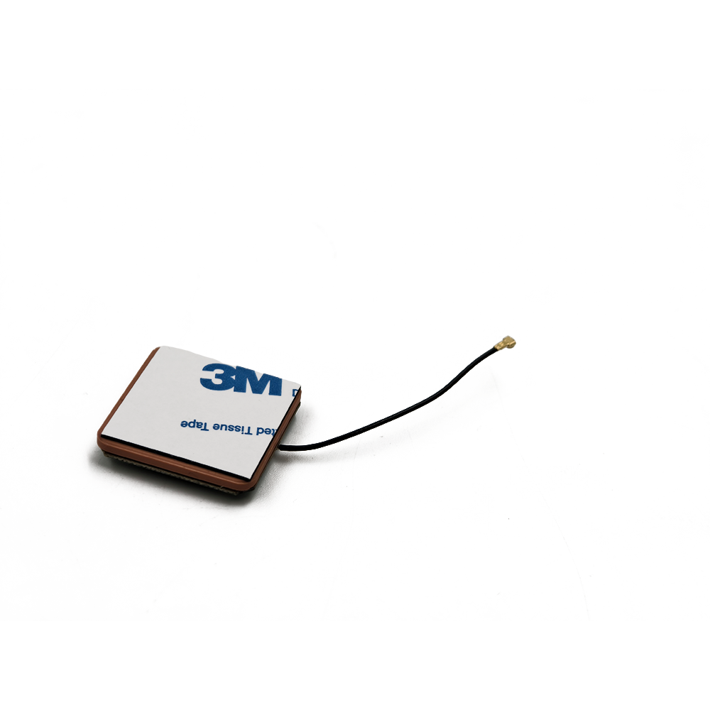
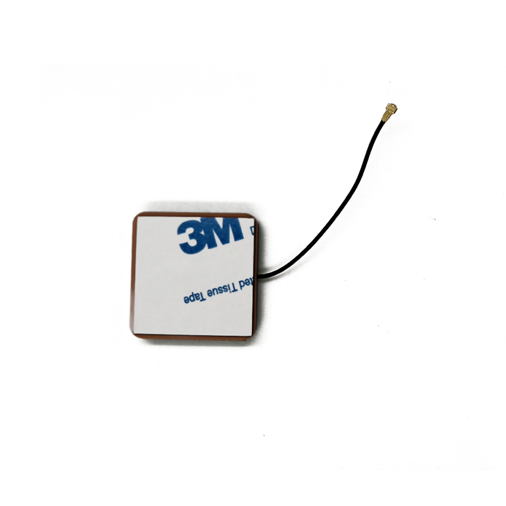
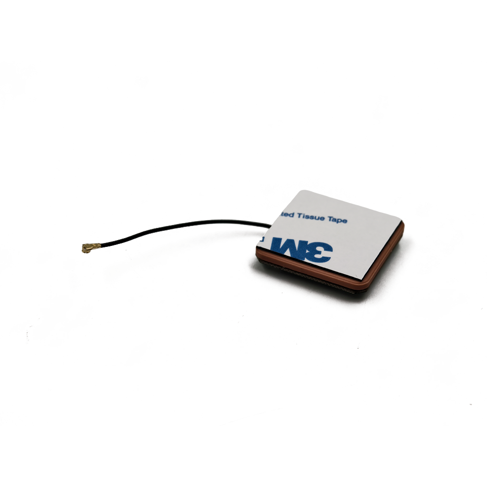
The ceramic material used in these antennas offers several advantages. Ceramic has a high dielectric constant, which allows for a compact antenna design. A smaller antenna size is not only beneficial for portability but also for integration into various devices, such as drones, autonomous vehicles, and handheld GNSS receivers. Additionally, ceramic is a stable material, resistant to environmental factors like temperature variations, humidity, and electromagnetic interference. This stability ensures consistent antenna performance over time and in different operating conditions.
The multi - system reception capability of RTK ceramic patch antennas is another crucial aspect. By being able to receive signals from multiple GNSS constellations simultaneously, the antenna can access a larger number of satellites. This redundancy increases the probability of having a clear line - of - sight to satellites, even in challenging environments such as urban canyons or areas with dense foliage. As a result, the positioning accuracy and reliability are enhanced.
2.1 Antenna Geometry
The design of RTK ceramic patch antennas typically starts with the geometry of the patch itself. The patch is usually a flat, rectangular or circular shape made of a conductive material, such as copper or gold, printed on a ceramic substrate. The dimensions of the patch are carefully calculated based on the frequencies of the GNSS signals it is designed to receive. For example, for GPS L1 frequency (1575.42 MHz), the patch dimensions are optimized to resonate at this frequency.
In multi - band antennas, which are designed to receive signals from multiple frequency bands (e.g., L1 and L2 in GPS), a stacked - patch or a more complex monolithic design may be employed. In a stacked - patch design, two or more patches are placed on top of each other, with each patch tuned to a different frequency band. The patches are separated by a dielectric layer, which helps in isolating the different frequency signals and maintaining their integrity.
2.2 Ceramic Substrate
The choice of ceramic substrate is a critical factor in the performance of the antenna. Ceramic materials, such as alumina or barium titanate, are commonly used due to their high dielectric constant. A high dielectric constant allows for a reduction in the physical size of the antenna while maintaining its electrical performance. For instance, an antenna with a high - dielectric - constant ceramic substrate can be made smaller compared to an antenna using a lower - dielectric - constant material for the same frequency range.
The ceramic substrate also provides mechanical stability to the antenna. It can withstand harsh environmental conditions, including temperature variations from - 40 °C to + 85 °C in many cases. This temperature stability is crucial as it ensures that the antenna's electrical properties, such as resonance frequency and impedance, remain consistent over a wide temperature range.
2.3 Feed Mechanism
There are two main types of feed mechanisms used in RTK ceramic patch antennas: single - feed and dual - feed. In a single - feed antenna, a single connection point is used to transfer the electrical signal to and from the patch. This design is relatively simple and cost - effective. However, it may have limitations in terms of circular polarization purity, especially over a wide frequency band.
Dual - feed antennas, on the other hand, use two feed points. The signals received at these two feed points are combined with a 90 - degree phase shift to produce a circularly polarized signal. This design significantly improves the rejection of cross - polarized signals, which are often caused by multi - path reflections. Since multi - path is a major source of positioning error in GNSS systems, dual - feed antennas are preferred in applications where high precision is required, such as in surveying and autonomous vehicle navigation.
2.4 Filtering and Amplification
To enhance the performance of the antenna, filtering and amplification components are often integrated into the antenna design. Filters are used to remove unwanted signals, such as those from out - of - band sources or interference from nearby electronic devices. Band - pass filters are commonly used to allow only the desired GNSS frequency bands to pass through while rejecting other frequencies.
Low - noise amplifiers (LNAs) are then used to amplify the weak GNSS signals received by the antenna. The LNAs are designed to have a low noise figure, which means they add minimal noise to the signal during amplification. This is crucial as the GNSS signals received by the antenna are extremely weak, typically in the order of - 130 dBm to - 160 dBm. By amplifying the signals while keeping the noise level low, the signal - to - noise ratio is improved, leading to better positioning accuracy.
3.1 GNSS Signal Reception
RTK ceramic patch antennas are designed to receive GNSS signals, which are electromagnetic waves transmitted by satellites orbiting the Earth. These signals carry information about the satellite's position, time, and other parameters. When the GNSS signals reach the antenna, they induce an electrical current in the conductive patch of the antenna.
The antenna is designed to be resonant at the frequencies of the GNSS signals. For example, for GPS L1 signals, the antenna's resonant frequency is tuned to 1575.42 MHz. At resonance, the antenna has the highest efficiency in receiving the signals, which means it can convert the maximum amount of the incoming electromagnetic energy into an electrical signal.
3.2 Circular Polarization
Most GNSS satellites transmit signals using right - handed circular polarization (RHCP). RTK ceramic patch antennas are designed to receive these RHCP signals. Circular polarization helps in reducing the effects of multi - path propagation, which occurs when the GNSS signals are reflected off buildings, terrain, or other objects before reaching the antenna.
In a circularly polarized antenna, the electric field vector of the received signal rotates in a circular path. This rotation allows the antenna to better reject signals that have been reflected and changed their polarization state. For example, if a GNSS signal is reflected off a building, it may change from RHCP to left - handed circular polarization (LHCP) or become linearly polarized. The RHCP - tuned antenna will have a lower sensitivity to these reflected signals, thus reducing the multi - path error.
3.3 RTK Principle
The Real - Time Kinematic (RTK) technique is what sets RTK ceramic patch antennas apart in terms of positioning accuracy. In an RTK system, there are two main components: a base station and a rover. The base station is located at a known, fixed position. It receives GNSS signals and calculates the errors in the signals due to factors such as satellite clock errors, atmospheric delays, and ephemeris errors.
The base station then transmits these error corrections to the rover in real - time, usually via a radio link or a cellular network. The rover, which is the device with the RTK ceramic patch antenna, also receives the GNSS signals. By applying the error corrections received from the base station to its own GNSS measurements, the rover can calculate its position with centimeter - level accuracy.
For example, if the base station calculates that the satellite clock error is causing a 1 - meter error in the position calculation, it will send this information to the rover. The rover can then subtract this 1 - meter error from its own position calculation, resulting in a more accurate position estimate.
4.1 Advantages
4.1.1 High Precision
The combination of multi - system GNSS reception and the RTK technique allows RTK ceramic patch antennas to achieve centimeter - level positioning accuracy. This high precision is essential in applications such as land surveying, where accurate measurements of land boundaries are crucial. In construction projects, the use of RTK - enabled antennas can ensure that buildings are constructed in the correct location with minimal errors.
4.1.2 Compact Design
Thanks to the use of ceramic materials with high dielectric constants, RTK ceramic patch antennas can be designed to be compact. This compact size makes them suitable for integration into a wide range of devices, from small handheld GNSS receivers to drones and wearable devices. For example, in a drone used for aerial mapping, the compact antenna can be easily installed without adding significant weight or taking up too much space.
4.1.3 Environmental Resistance
Ceramic is a highly stable material that is resistant to environmental factors such as temperature variations, humidity, and electromagnetic interference. This means that RTK ceramic patch antennas can operate reliably in a wide range of environmental conditions. In outdoor applications, where the antenna may be exposed to extreme temperatures or high humidity, the ceramic material ensures that the antenna's performance remains consistent.
4.1.4 Multi - System Compatibility
The ability to receive signals from multiple GNSS constellations is a significant advantage. By accessing signals from GPS, GLONASS, Galileo, and BeiDou, the antenna can increase the number of available satellites for positioning. This redundancy improves the reliability of the positioning system, especially in challenging environments where some satellites may be blocked. For example, in an urban area with tall buildings, the multi - system antenna can still find enough satellites to provide accurate positioning by switching between different constellations.
4.2 Challenges
4.2.1 Multi - Path Interference
Despite the use of circular polarization and other techniques to reduce multi - path effects, multi - path interference remains a challenge for RTK ceramic patch antennas. In complex environments, such as urban canyons with many tall buildings or areas with rough terrain, GNSS signals can be reflected multiple times before reaching the antenna. These reflected signals can interfere with the direct signals, causing errors in the position calculation. Advanced signal processing techniques are constantly being developed to further mitigate multi - path interference.
4.2.2 Signal Blockage
In some environments, such as dense forests or indoor spaces, GNSS signals can be blocked. The ceramic patch antenna may not be able to receive a sufficient number of signals from satellites, leading to poor positioning performance. To address this issue, additional sensors, such as inertial measurement units (IMUs), can be integrated with the GNSS receiver. The IMU can provide short - term position estimates when the GNSS signals are blocked, allowing for a more continuous and reliable positioning solution.
4.2.3 Cost
The production of high - quality RTK ceramic patch antennas, especially those with advanced features such as dual - feed mechanisms and multi - band capabilities, can be costly. The use of high - precision manufacturing processes and expensive materials contributes to the high cost. This cost factor may limit the widespread adoption of these antennas in some price - sensitive applications. However, as technology advances and economies of scale are achieved, the cost is expected to decrease.
4.2.4 Complexity in Design and Calibration
Designing an RTK ceramic patch antenna that can perform optimally across multiple GNSS constellations and frequency bands is a complex task. The antenna design needs to consider factors such as impedance matching, radiation pattern, and polarization purity for each frequency band. Additionally, calibration of the antenna is crucial to ensure accurate positioning. Calibration involves adjusting the antenna's parameters to account for manufacturing tolerances and environmental factors. This complexity requires highly skilled engineers and sophisticated testing equipment.
5.1 Applications
5.1.1 Surveying and Mapping
In land surveying, RTK ceramic patch antennas are used to accurately measure land boundaries, elevation levels, and topographical features. The centimeter - level accuracy provided by these antennas ensures that property lines are precisely defined, and construction projects are based on accurate survey data. In hydrographic surveying, which involves mapping underwater terrain, RTK - enabled antennas are used to precisely locate the survey vessel, allowing for accurate mapping of the seabed.
5.1.2 Agriculture
In precision agriculture, RTK ceramic patch antennas are used in tractors and other agricultural equipment. The accurate positioning provided by these antennas enables farmers to precisely apply fertilizers, pesticides, and seeds. This not only reduces waste but also increases crop yields. For example, a tractor equipped with an RTK - enabled antenna can be programmed to apply different amounts of fertilizer based on the specific nutrient requirements of different parts of the field.
5.1.3 Autonomous Vehicles
Autonomous vehicles rely on highly accurate positioning to navigate safely. RTK ceramic patch antennas, combined with other sensors such as lidar and cameras, provide the necessary positioning accuracy for autonomous vehicles to operate. The ability to receive signals from multiple GNSS constellations ensures that the vehicle can maintain accurate positioning even in challenging environments, such as when driving through tunnels or in areas with tall buildings.
5.1.4 Drone Applications
Drones are increasingly being used for various applications, including aerial photography, mapping, and inspection. RTK ceramic patch antennas allow drones to precisely locate themselves in the air, which is essential for tasks such as creating accurate 3D maps or inspecting infrastructure. For example, in a drone - based inspection of power lines, the accurate positioning provided by the RTK antenna ensures that the drone can fly close to the power lines and capture high - quality images for inspection.
5.2 Future Trends
5.2.1 Integration with Other Technologies
In the future, RTK ceramic patch antennas are likely to be more closely integrated with other emerging technologies. For example, there will be increased integration with 5G communication technology. The high - speed and low - latency communication capabilities of 5G can be used to transmit RTK correction data more efficiently, further improving the positioning accuracy. Additionally, integration with artificial intelligence (AI) and machine learning (ML) algorithms is expected. AI and ML can be used to process the large amounts of GNSS data received by the antenna more effectively, improving signal processing and reducing multi - path interference.
5.2.2 Miniaturization and Cost Reduction
As technology advances, there will be a continued trend towards miniaturization of RTK ceramic patch antennas. This will enable their integration into even smaller devices, such as smartwatches and other wearable devices. At the same time, cost - reduction efforts are likely to make these antennas more accessible to a wider range of applications. New manufacturing techniques and the use of more cost - effective materials may contribute to this cost reduction.
5.2.3 Expansion of GNSS Constellations
New GNSS constellations are being developed, and existing constellations are being expanded. RTK ceramic patch antennas will need to be designed to be compatible with these new and expanded constellations. This will further increase the number of available satellites for positioning, leading to even higher accuracy and reliability. For example, as more satellites are added to the Galileo constellation, RTK antennas will be updated to take full advantage of the additional signals.
5.2.4 Improved Signal Processing
Research is ongoing to develop better signal processing techniques for RTK ceramic patch antennas. These techniques will focus on further reducing multi - path interference, improving the reception of weak signals, and enhancing the overall performance of the antenna in challenging environments. For example, new algorithms may be developed to more accurately separate direct and reflected GNSS signals, reducing the impact of multi - path on positioning accuracy.
Conclusion
RTK ceramic patch antennas have become an indispensable component in the field of multi - system GNSS reception. Their ability to provide high - precision positioning, combined with a compact and environmentally resistant design, has made them suitable for a wide range of applications. The working principles of these antennas, including GNSS signal reception, circular polarization, and the RTK technique, are well - understood and form the basis for their high - performance operation.
Despite the challenges such as multi - path interference, signal blockage, cost, and design complexity, continuous research and development efforts are being made to overcome these obstacles. The applications of RTK ceramic patch antennas span across various industries, including surveying, agriculture, autonomous vehicles, and drone technology, and are expected to expand further in the future.
Looking ahead, future trends such as integration with other technologies, miniaturization, cost reduction, compatibility with expanded GNSS constellations, and improved signal processing hold great promise for the continued evolution of RTK ceramic patch antennas. As these trends materialize, RTK ceramic patch antennas will play an even more significant role in enabling highly accurate and reliable positioning solutions in an increasingly connected and technology - driven world.

 86 0755 2819 9597
Lucy Yang | lucy.y@toxutech.com
Nicole Li | nicole@toxutech.com
Dotty Zhao | sales04@toxutech.com
Global Business Director / Sales Team / Global Operations


 En
En Cn
Cn Korean
 Home >


