

-
Products -PCBA Manufacturing RF Connectors RF Cable Assemblys Embedded Antennas External Antennas Positioning Chips and Modules
RF Connectors

RF Cable Assemblys
Embedded Antennas
External Antennas
Positioning Chips and Modules


 Language


Language


In the realm of geospatial measurement, precision is not merely a goal but a necessity. From land surveying and construction alignment to infrastructure monitoring and environmental mapping, the ability to capture accurate positional data with minimal error can make or break a project. At the heart of this precision lies the Global Navigation Satellite System (GNSS) antenna, a critical component that receives signals from multiple satellite constellations to determine exact geographic coordinates. Among the various types of GNSS antennas available, the precision surveying GNSS antenna stands out for its ability to deliver sub-centimeter level accuracy, even in challenging environments.
This article focuses on a cutting-edge precision surveying GNSS antenna designed to meet the rigorous demands of professional geospatial applications. What sets this antenna apart is its unique combination of advanced features: high phase center stability, reliable tracking in obstructed environments, robust anti-interference capabilities, and a compact, durable design. These attributes, when combined with its broad compatibility across major satellite constellations (GPS, BDS, GLONASS, Galileo), make it an indispensable tool for surveyors, engineers, and geoscientists worldwide.
To understand the significance of this antenna, it is essential to first grasp the role of GNSS in precision surveying. GNSS relies on signals transmitted by satellites orbiting the Earth, which are received by ground-based antennas and processed to calculate precise positions. The accuracy of this process depends heavily on the antenna’s ability to capture these signals consistently, interpret them correctly, and minimize errors introduced by environmental factors, signal interference, or structural inconsistencies. This antenna addresses each of these challenges through innovative engineering, making it a leader in its class.
2.1 High Phase Center Stability: The Foundation of Measurement Accuracy
At the core of any precision GNSS antenna is its phase center—the point within the antenna where the received satellite signals are considered to be processed. For accurate measurements, this phase center must remain stable regardless of the satellite’s position in the sky or the antenna’s orientation. A unstable phase center can introduce significant errors, as the antenna’s apparent position shifts relative to the actual ground location being surveyed.
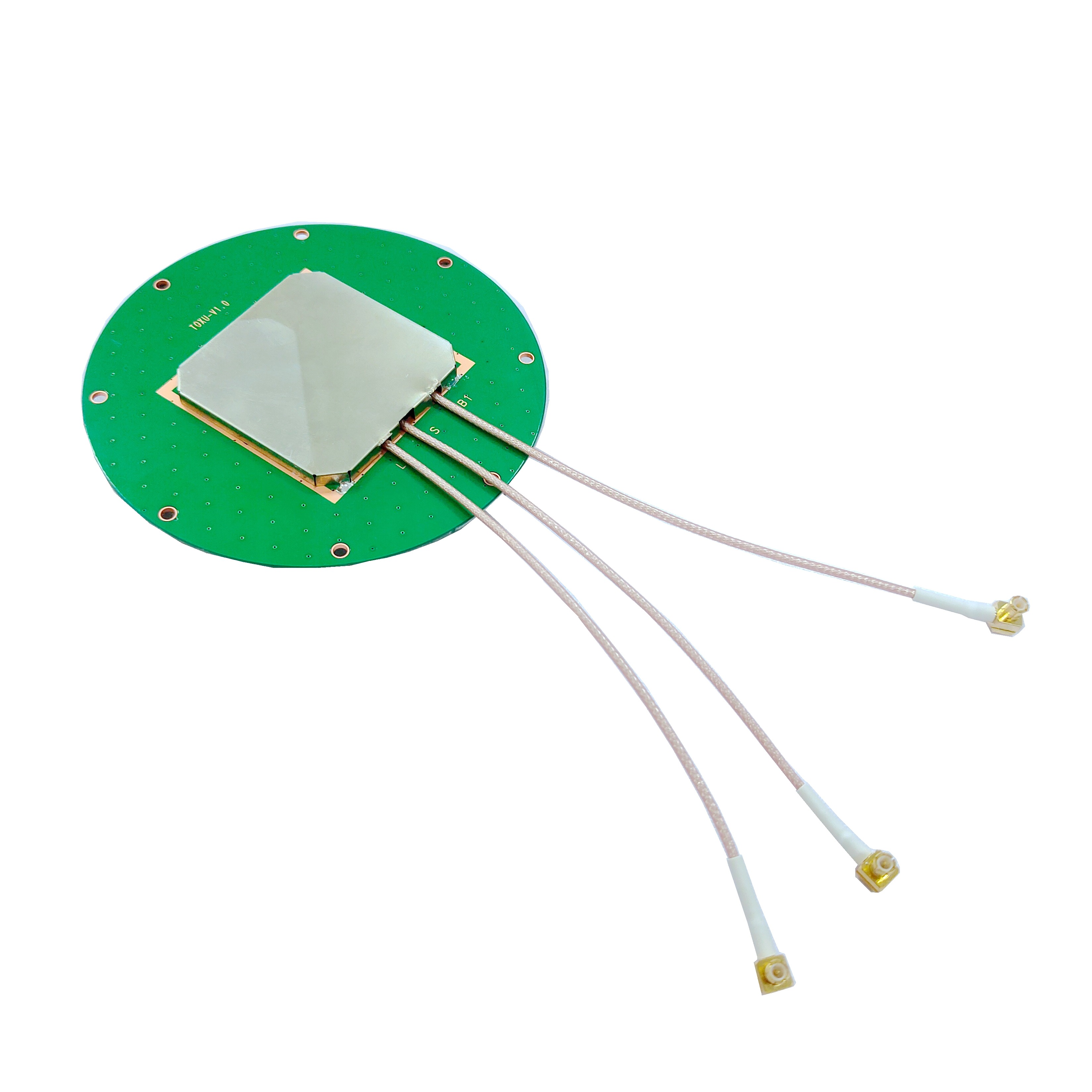
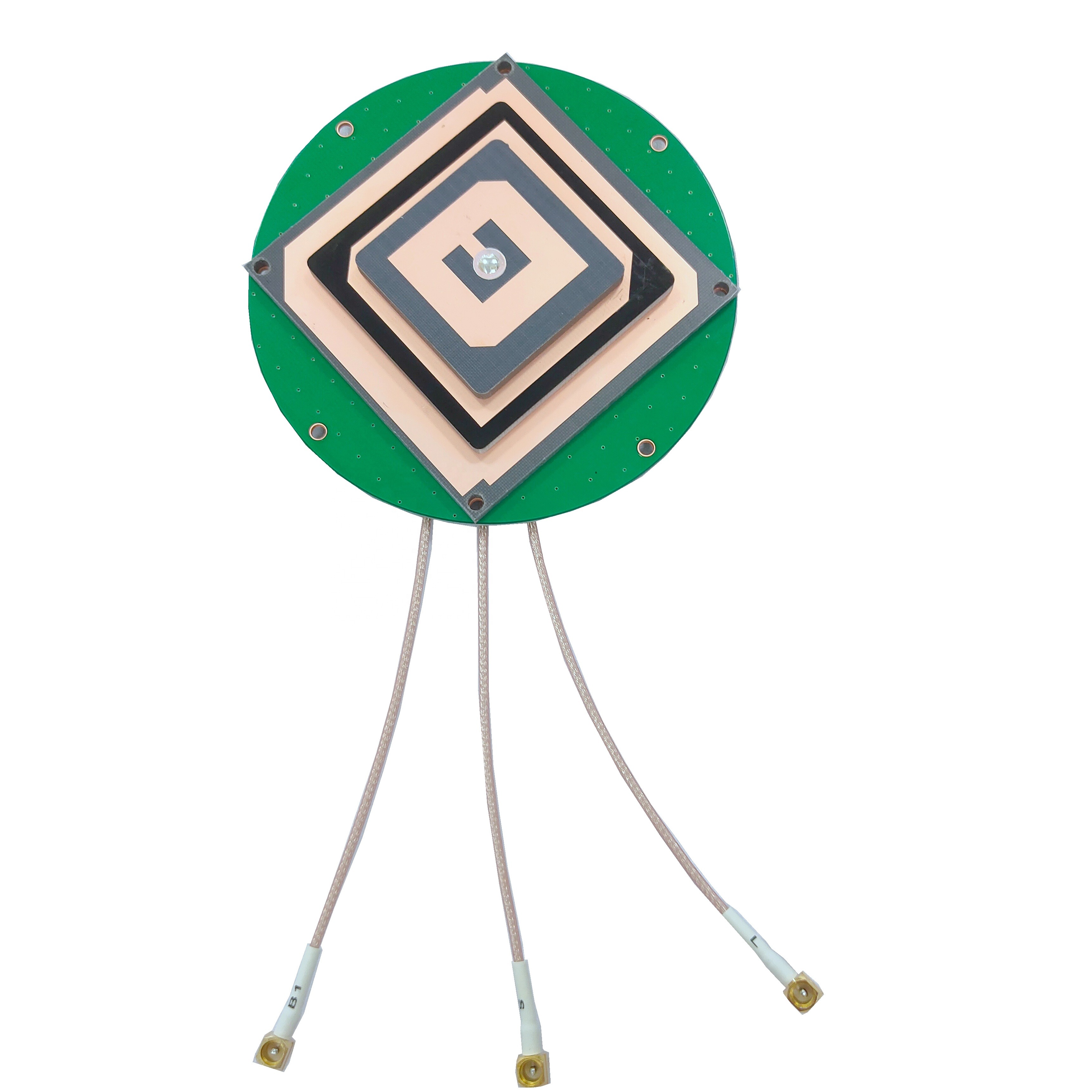
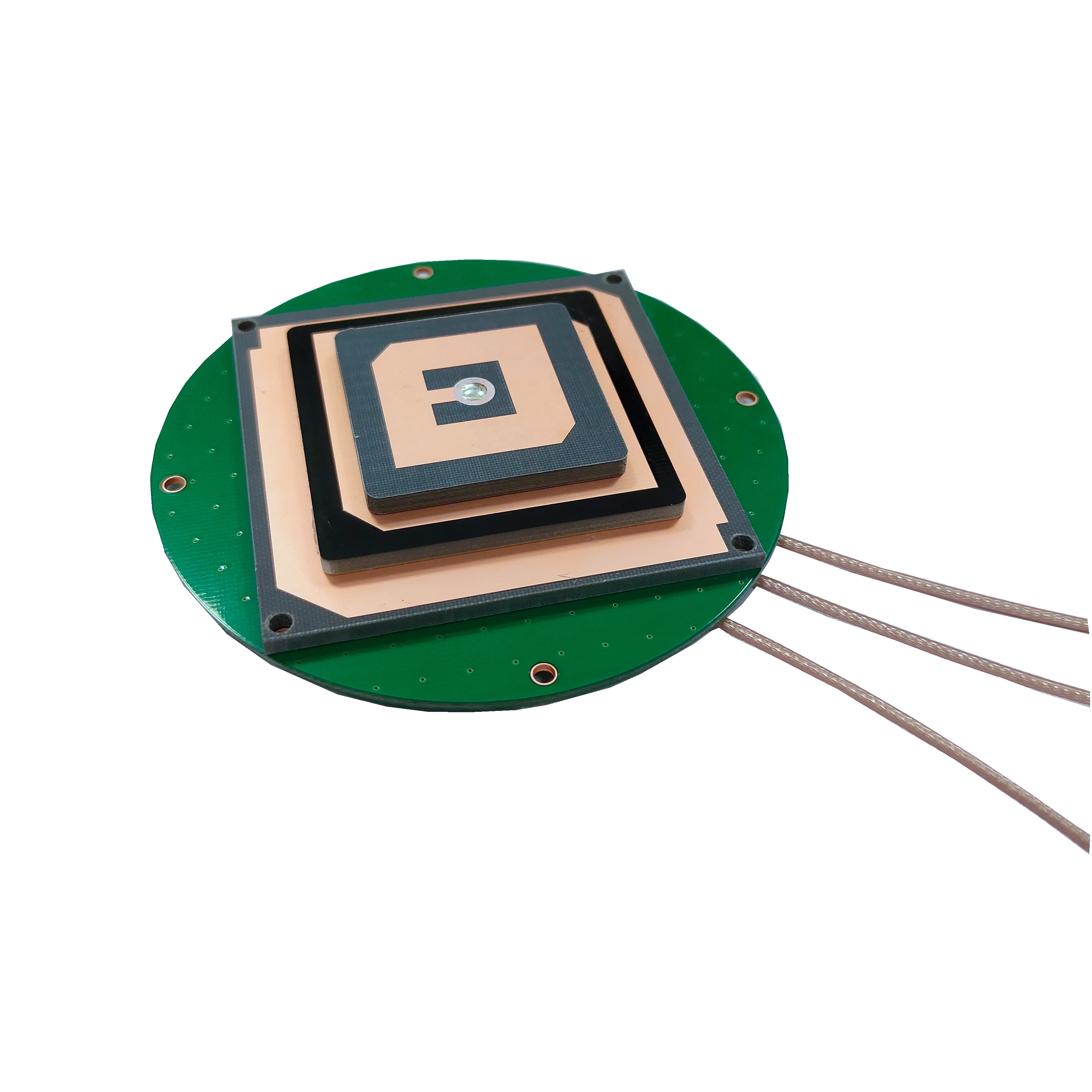
This precision surveying GNSS antenna tackles this challenge through a multi-feed point design and a completely symmetrical antenna structure. The multi-feed point design involves incorporating multiple signal reception points within the antenna, which work in tandem to average out minor variations in signal arrival times. This averaging effect ensures that the phase center remains consistent, even when signals come from extreme angles (e.g., low-elevation satellites near the horizon).
The symmetrical structure, meanwhile, eliminates directional biases. By ensuring that the antenna’s physical and electrical properties are uniform across all axes, it avoids preferential treatment of signals from specific directions. This symmetry is particularly critical in applications where the antenna may be subjected to slight tilts or rotations, such as in mobile surveying units or airborne mapping systems.
The result is a phase center stability that minimizes measurement errors. In practical terms, this means that repeated measurements of the same point will yield consistent results, with deviations often measured in millimeters rather than centimeters. For projects like railway alignment, where even a small error can lead to costly construction mistakes, or in deformation monitoring of dams and bridges, where subtle positional changes must be detected over time, this level of stability is invaluable.
2.2 Tracking in Challenging Environments: Overcoming Obstructions and Signal Weakness
One of the most common challenges in GNSS surveying is maintaining signal reception in environments where satellites are partially or fully obstructed. Urban canyons (areas surrounded by tall buildings), dense forests, and mountainous terrain can block or reflect satellite signals, leading to signal loss or multipath interference (where signals bounce off surfaces before reaching the antenna, causing timing errors).
This antenna addresses these issues through three key design elements: high gain, a wide pattern beam, and excellent reception of low-elevation angle signals.
High gain refers to the antenna’s ability to amplify weak signals. In areas with partial obstructions, satellite signals may be attenuated as they pass through obstacles like tree foliage or building facades. The antenna’s high gain ensures that even these weakened signals are captured and processed effectively.
Wide pattern beam expands the antenna’s field of view, allowing it to receive signals from a broader range of satellite positions. This is particularly useful in urban environments, where satellites directly overhead may be visible, but those at lower angles are blocked by buildings. A wide beam ensures that the antenna can still lock onto the available satellites, maintaining a sufficient number of connections to calculate a precise position.
Low-elevation angle reception is perhaps the most critical feature for challenging environments. Satellites at low elevations (less than 15 degrees above the horizon) are often the only ones visible in deep canyons or dense forests. However, signals from these satellites are more prone to attenuation and multipath interference because they travel through more of the Earth’s atmosphere and are more likely to reflect off nearby surfaces. This antenna is engineered to filter out noise from these low-angle signals while preserving their integrity, ensuring that they contribute meaningfully to position calculations.
In field tests, this antenna has demonstrated its ability to maintain stable connections with 8-10 satellites even in areas where conventional antennas struggle to track 4-5. For example, in a dense urban neighborhood with 30-story buildings, the antenna continued to provide centimeter-level accuracy, whereas a standard antenna reported errors of 1-2 meters due to signal dropouts. Similarly, in forested regions, where canopy cover blocks much of the sky, the antenna’s low-elevation reception allowed surveyors to complete their work without waiting for clear sky conditions.
2.3 Strong Anti-Interference Ability: Mitigating Unwanted Signals
In today’s electromagnetic landscape, GNSS signals face increasing competition from other radio frequency (RF) sources. These include intentional jammers (used illegally to disrupt GNSS in certain areas), as well as unintentional interference from nearby communication towers, radar systems, or industrial equipment. Such interference can corrupt GNSS signals, leading to positioning errors or complete signal loss.
This precision surveying GNSS antenna employs a pre-filtering and multi-stage filtering scheme to combat interference.
Pre-filtering occurs at the front end of the antenna’s signal processing chain, where a band-pass filter allows only the frequencies used by GNSS constellations (e.g., GPS L1 at 1575.42 MHz, BDS B1 at 1561.098 MHz) to pass through, blocking out-of-band signals from the start. This reduces the workload on subsequent filtering stages and prevents strong interference from overwhelming the system.
Multi-stage filtering builds on this by incorporating additional filters at different points in the signal processing pathway. Each stage targets specific types of interference: for example, one stage may focus on suppressing narrowband interference from nearby radio transmitters, while another targets broadband noise from industrial machinery. This layered approach ensures that even complex interference scenarios are managed effectively.
The result is an antenna that can operate reliably in high-electromagnetic-noise environments. In regions near airports (where radar systems emit strong RF signals) or industrial zones (with heavy machinery), the antenna maintains its accuracy, whereas unfiltered antennas may report erratic positions or fail to lock onto satellites altogether. This anti-interference capability is particularly critical for critical infrastructure projects, such as pipeline monitoring or power grid alignment, where reliable positioning data is essential for safety and functionality.
2.4 Compact, Lightweight, and Durable: Designed for Field Conditions
Precision surveying often takes place in harsh outdoor environments, from scorching deserts to freezing mountain tops. An antenna must therefore be rugged enough to withstand extreme weather, physical stress, and prolonged exposure to the elements—all while remaining easy to transport and install.
This antenna excels in this regard, with a design that prioritizes compactness, lightweight construction, low wind resistance, and robust environmental protection.
Compact and lightweight: The antenna’s small form factor (typically measuring less than 15 cm in diameter and weighing under 500 grams) makes it easy to carry in field kits and mount on surveying poles, drones, or vehicles. This is a significant advantage over bulkier antennas, which can be cumbersome to transport and may require additional support structures.
Low wind resistance: Its streamlined shape minimizes drag, making it suitable for use in high-wind environments such as open plains or coastal areas. This reduces the risk of the antenna being dislodged or tilted during measurements, which could introduce errors.
Environmental protection: The antenna boasts an IP67 protection rating, meaning it is dust-tight and can withstand immersion in up to 1 meter of water for 30 minutes. This makes it resistant to rain, snow, and dust, ensuring reliable operation in inclement weather. Additionally, the outer casing is treated to resist ultraviolet (UV) radiation, preventing degradation from prolonged sun exposure. This UV resistance is crucial for antennas used in sunny climates, where UV rays can cause plastic casings to become brittle over time, compromising both structural integrity and performance.
These durability features ensure that the antenna can be deployed in a wide range of field conditions without sacrificing accuracy. Whether used in the Sahara Desert, the Arctic tundra, or a tropical rainforest, it remains operational, reducing downtime and ensuring that surveying projects stay on schedule.
To fully appreciate the capabilities of this precision surveying GNSS antenna, it is essential to examine its technical parameters, which define its performance limits and compatibility with various systems.
3.1 Frequency Range: Multi-Constellation Compatibility
The antenna is designed to receive signals from all major global and regional GNSS constellations, ensuring maximum coverage and redundancy. Its frequency range includes:
GPS: L1 (1575.42 MHz), L2 (1227.60 MHz), L5 (1176.45 MHz)
BDS (BeiDou Navigation Satellite System): B1 (1561.098 MHz), B2 (1207.14 MHz), B3 (1268.52 MHz)
GLONASS: G1 (1602.0 MHz), G2 (1246.0 MHz), G3 (1202.025 MHz)
Galileo: E1 (1575.42 MHz), E5a (1176.45 MHz), E5b (1207.14 MHz)
This broad frequency coverage allows the antenna to leverage signals from over 100 satellites (depending on constellation availability), ensuring that even in challenging environments, there are enough satellites to calculate a precise position. Multi-constellation compatibility also reduces reliance on any single system, mitigating the risk of outages or degradation in one constellation affecting survey results.
3.2 Electrical Specifications: Performance Metrics
Type: GPS/GNSS Antenna (specifically optimized for precision surveying)
Polarization: Right-Hand Circular Polarization (RHCP). GNSS satellites transmit signals with RHCP, and using an RHCP antenna ensures maximum signal reception efficiency. Circular polarization is also more robust against signal reflections (which often convert polarization to left-hand), reducing multipath errors.
Voltage Standing Wave Ratio (V.S.W.R): Maximum 2.0. VSWR measures how well the antenna is matched to the transmission line (cable) connecting it to the receiver. A VSWR of 2.0 or lower indicates efficient power transfer, with minimal signal reflection back from the antenna to the receiver—critical for maintaining signal strength and reducing noise.
Connector: TNC (Threaded Neill-Concelman). TNC connectors are widely used in RF applications for their secure, weather-resistant connection. They provide a reliable interface between the antenna and the coaxial cable, ensuring that signal loss at the connection point is minimized.
3.3 Practical Parameters: Logistics and Customization
Custom made: Support for customization. This includes options for alternative connectors (e.g., SMA, N-type), specialized mounting hardware, or modified frequency ranges for specific applications.
Logo: Support for custom branding, allowing organizations to mark antennas with their logo for inventory management or branding purposes.
Package: Paper box, designed to protect the antenna during shipping while minimizing environmental impact.
Delivery date: 14 days from order, ensuring quick turnaround for time-sensitive projects.
Minimum Order Quantity (MOQ): 1 piece, making it accessible for small-scale projects or individual surveyors, as well as large orders for enterprise clients.
Origin: China, reflecting the country’s growing role in manufacturing high-precision GNSS components.
These parameters collectively demonstrate that the antenna is not only technically advanced but also practical for real-world use, with flexibility to adapt to diverse project requirements.
The precision, reliability, and durability of this GNSS antenna make it suitable for a wide range of professional applications. Below are some of the key sectors where it excels:
4.1 Land Surveying and Mapping
In traditional land surveying, the goal is to determine the boundaries, elevations, and features of a parcel of land with legal or engineering accuracy. This antenna’s high phase center stability ensures that property lines, topographic contours, and construction stakes are placed with sub-centimeter precision. For example, in cadastral surveying (mapping land ownership), even a small error can lead to legal disputes. The antenna’s ability to maintain consistency across repeated measurements eliminates this risk, providing surveyors with confidence in their data.
4.2 Construction and Infrastructure Alignment
Large-scale construction projects—such as highways, bridges, and skyscrapers—require precise alignment to ensure structural integrity and safety. The antenna’s tracking capability in obstructed environments is particularly valuable here, as construction sites are often surrounded by cranes, scaffolding, and partially built structures that can block satellite signals. By maintaining signal lock even in these conditions, the antenna ensures that foundations are laid correctly, columns are aligned vertically, and structural components fit together as designed.
4.3 Deformation Monitoring
Critical infrastructure like dams, nuclear power plants, and tall buildings undergoes subtle deformation over time due to factors like soil settlement, temperature changes, and seismic activity. Detecting these changes early is essential to prevent catastrophic failures. The antenna’s phase center stability and low-elevation tracking allow for continuous, high-precision monitoring. For example, in dam monitoring, the antenna can detect vertical or horizontal movements as small as 1-2 millimeters, providing engineers with data to assess structural health and take corrective action if needed.
4.4 Precision Agriculture
Modern agriculture increasingly relies on GNSS for precision farming techniques, such as variable-rate seeding, fertilization, and irrigation. By mapping fields with centimeter-level accuracy, farmers can optimize resource use, reduce waste, and increase yields. This antenna’s durability—including its IP67 rating and UV resistance—makes it suitable for use in agricultural environments, where exposure to rain, dust, and sunlight is constant. Its ability to track satellites even in low-elevation angles ensures coverage over large, open fields, where the horizon is often unobstructed but satellites may be at low angles during early morning or late afternoon.
4.5 Environmental and Coastal Mapping
Coastal erosion, glacier movement, and wetland changes are critical environmental processes that require accurate monitoring. This antenna’s compact size and low wind resistance make it ideal for mounting on boats, drones, or portable monitoring stations in remote areas. Its anti-interference capabilities are also valuable in coastal regions, where radar systems and maritime communication devices may generate RF noise. By providing reliable positioning data in these challenging environments, the antenna helps scientists track environmental changes and develop effective conservation strategies.
To maximize the accuracy and longevity of this precision surveying GNSS antenna, proper installation and maintenance are essential. Below are best practices for both:
5.1 Installation Guidelines
Mounting Location: The antenna should be mounted in a location with an unobstructed view of the sky as much as possible. While it can track low-elevation satellites, avoiding nearby obstructions (e.g., trees, buildings) will minimize multipath interference. For fixed installations (e.g., monitoring stations), a clear view of at least 10 degrees above the horizon is recommended.
Orientation: The antenna should be mounted horizontally (level) to ensure that its symmetrical structure functions as designed. Most antennas come with a built-in bubble level or can be paired with a leveling mount to achieve this.
Cable Management: The TNC connector should be securely tightened to prevent signal loss or water ingress. Coaxial cables connecting the antenna to the receiver should be routed to avoid sharp bends, which can cause signal attenuation. If the cable is exposed to the elements, it should be rated for outdoor use and protected with conduit where necessary.
Grounding: In areas with frequent lightning, the antenna should be connected to a lightning protection system to prevent damage from electrical surges. This may involve mounting the antenna on a grounded metal pole or using a surge protector in the signal path.
5.2 Maintenance Practices
Regular Inspection: The antenna’s outer casing should be inspected periodically for cracks, UV damage, or signs of corrosion. The TNC connector should be checked for tightness and cleanliness—dust or moisture in the connector can degrade signal quality.
Cleaning: The antenna’s surface can be cleaned with a soft, damp cloth to remove dirt, bird droppings, or other debris that may block signals. Abrasive cleaners should be avoided, as they can scratch the casing or interfere with the antenna’s RF properties.
Cable Checks: Coaxial cables should be inspected for damage (e.g., cuts, kinks) and replaced if necessary. Connectors can be cleaned with isopropyl alcohol to remove oxidation or debris.
Firmware Updates: If the antenna is paired with a receiver that has firmware, keeping the firmware up to date can ensure compatibility with new satellite signals or performance improvements.
By following these installation and maintenance steps, users can ensure that the antenna operates at peak performance for years, providing consistent, accurate data across hundreds of projects.
The precision surveying GNSS antenna described in this article represents a significant advancement in geospatial technology. Its combination of high phase center

 86 0755 2819 9597
Lucy Yang | lucy.y@toxutech.com
Nicole Li | nicole@toxutech.com
Dotty Zhao | sales04@toxutech.com
Global Business Director / Sales Team / Global Operations


 En
En Cn
Cn Korean
 Home >


