

-
Products -PCBA Manufacturing RF Connectors RF Cable Assemblys Embedded Antennas External Antennas Positioning Chips and Modules
RF Connectors

RF Cable Assemblys
Embedded Antennas
External Antennas
Positioning Chips and Modules


 Language


Language


The advent of Real-Time Kinematic (RTK) GPS technology revolutionized land surveying by delivering centimeter-level accuracy in real-time. This capability shifted the industry from labor-intensive, time-consuming methods to highly efficient, data-rich workflows. At the heart of any RTK system is the antenna, the critical component responsible for capturing the faint signals from GNSS satellites orbiting over 20,000 kilometers away. While early RTK systems were often bulky, tethered to large base stations with choke ring antennas, a parallel revolution has been occurring in miniaturization and portability. The portable GPS RTK antenna is the product of this evolution, embodying the relentless pursuit of high performance in a compact, rugged, and user-friendly form factor.
1. Overview: The Miniaturized Engine of Mobile Precision
The advent of Real-Time Kinematic (RTK) GPS technology revolutionized land surveying by delivering centimeter-level accuracy in real-time. This capability shifted the industry from labor-intensive, time-consuming methods to highly efficient, data-rich workflows. At the heart of any RTK system is the antenna, the critical component responsible for capturing the faint signals from GNSS satellites orbiting over 20,000 kilometers away. While early RTK systems were often bulky, tethered to large base stations with choke ring antennas, a parallel revolution has been occurring in miniaturization and portability. The portable GPS RTK antenna is the product of this evolution, embodying the relentless pursuit of high performance in a compact, rugged, and user-friendly form factor.
A portable RTK antenna is specifically designed for use on a rover pole, typically between 1.8 to 2.2 meters in length, carried by a surveyor for hours on end. This primary use case dictates its entire philosophy: it must be lightweight, compact, durable, and power-efficient, all while maintaining the rigorous performance standards necessary for geodetic-grade work. It is the mobile counterpart to the often larger and heavier base station antenna, though the line between them is increasingly blurred as technology improves.
The driving force behind the development of portable antennas was the need for surveyors to work more efficiently in diverse and challenging field conditions. A large, heavy choke ring antenna is impractical for a rover; it creates a top-heavy pole that is fatiguing to carry and prone to wobble, which itself can introduce measurement error. The portable antenna had to solve the multipath problem—the primary nemesis of GPS accuracy—through innovative means other than sheer size and weight.
The evolution of these antennas mirrors advancements in materials science, electromagnetic simulation software, and electronic miniaturization. Early rover antennas were simple patch antennas with small ground planes. They were portable but suffered from poorer multipath rejection and less stable phase center characteristics compared to their larger counterparts. The breakthrough came with the development of miniaturized choke rings, artificial magnetic conductor (AMC) surfaces, and advanced stacked-patch designs. These technologies allowed engineers to "trick" the electromagnetic waves into behaving as if they were interacting with a much larger structure, thereby achieving impressive multipath rejection from a low-profile package.
A modern portable RTK antenna is a masterpiece of engineering compromise. Its key characteristics are a direct response to the demands of field mobility:
Low Profile and Lightweight: Typically less than 10 cm in height and weighing only a few hundred grams, it minimizes inertia on the pole, allowing the surveyor to hold it steady and reducing pole sway error.
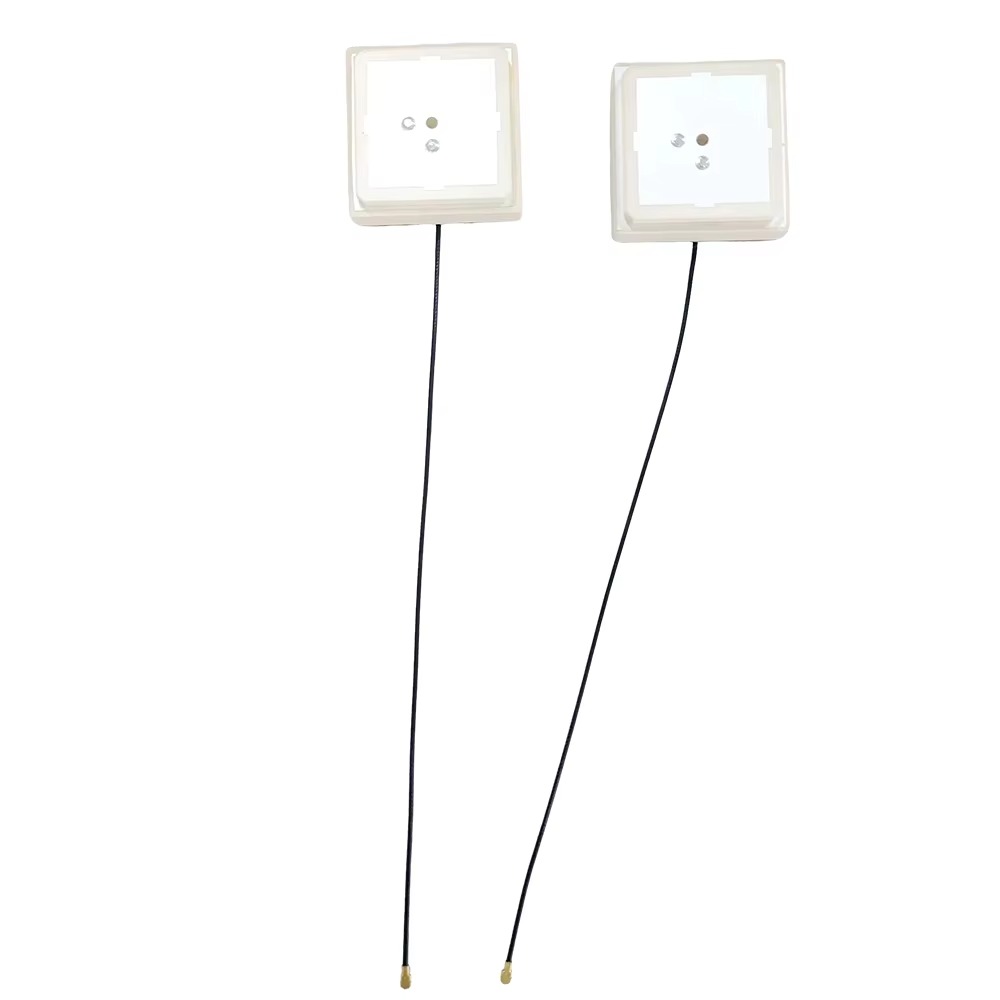
Ruggedized Construction: It is built to withstand the harsh realities of field work: being dropped, exposed to rain, dust, and extreme temperatures. Its radome is made from high-strength, RF-transparent materials like polycarbonate or ABS plastic, often with a UV inhibitor to prevent sun degradation.
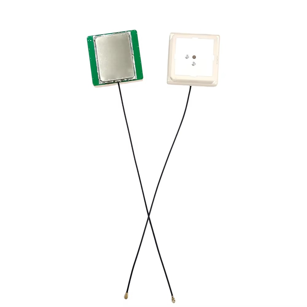
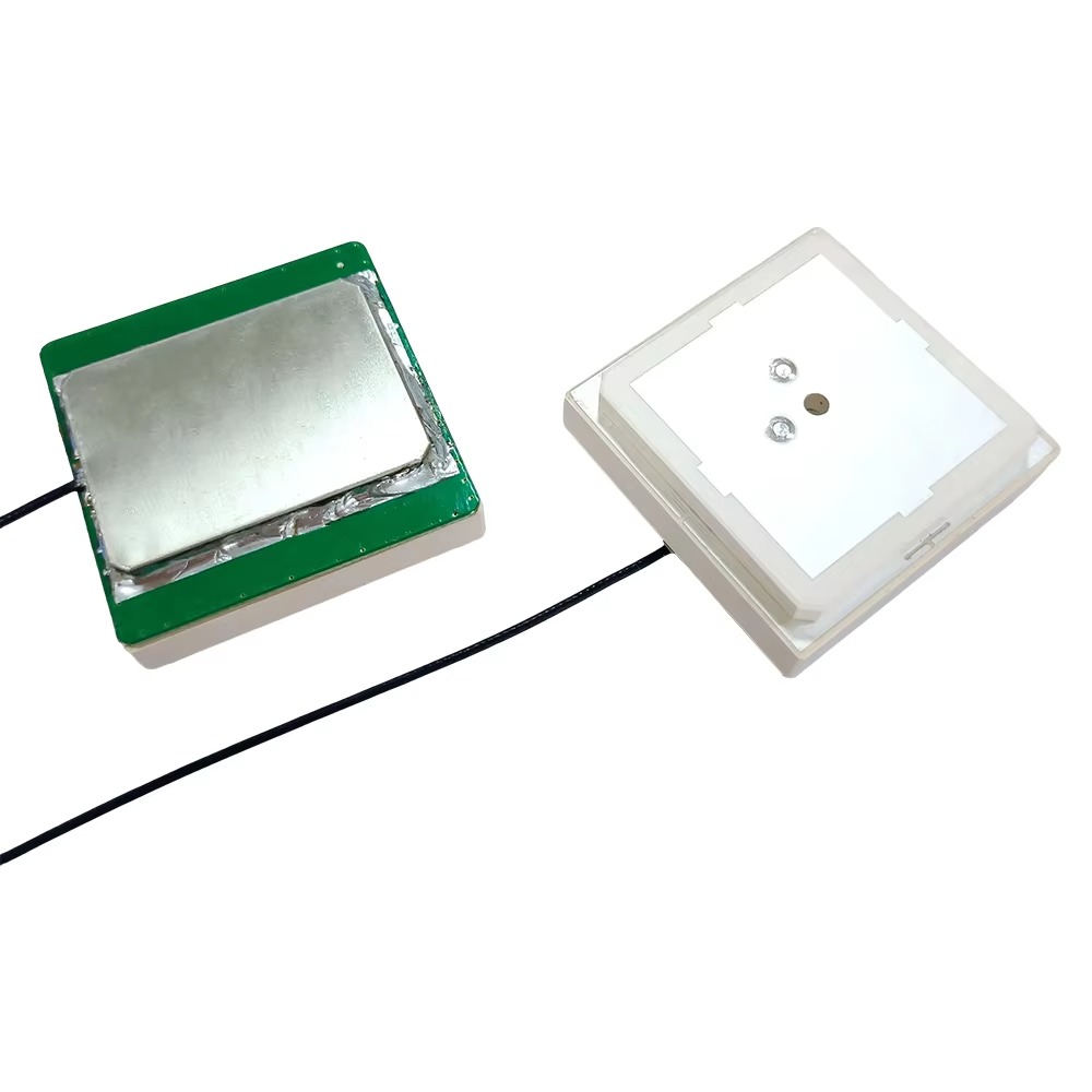
Integrated Design: Most portable antennas integrate the antenna element, ground plane, and Low-Noise Amplifier (LNA) into a single, sealed unit. Many also incorporate a survey-grade tribrach or a quick-release mechanism for easy mounting on the pole.
Power Efficiency: Powered directly from the receiver via the coaxial cable, its LNA is designed to provide optimal gain without excessive power draw, preserving the rover receiver's battery life.
Maintained Performance: Despite its size, it must still exhibit a stable phase center, good gain towards the horizon, and effective multipath suppression. This is where the most sophisticated engineering is focused.
In practice, the portable antenna is the point of measurement. The surveyor ensures the pole is vertical, and the receiver calculates the position of the antenna's phase center. Its portability enables the entire concept of mobile, high-precision data collection, from topographic surveys and construction layout to asset mapping and GIS data collection. It is the unsung hero that brings the power of centimeter-accurate GNSS directly to the fingertips of the field professional, enabling them to measure the world with unprecedented speed and accuracy.
The design and construction of a portable GPS RTK antenna is a far more complex challenge than it appears. Engineers are tasked with replicating the performance of a large, stationary antenna in a package that is a fraction of the size and weight, and that can survive being carried through brush, bumped against doors, and exposed to all weather conditions. Every material, shape, and electronic component is meticulously chosen to balance these often conflicting demands of performance, durability, and portability.
The core of most portable antennas is a stacked patch antenna design. This is an evolution of the standard microstrip patch. It consists of two or more parasitic patch elements stacked on top of the main driven patch element, separated by dielectric layers. This multi-resonant structure allows the antenna to operate efficiently across multiple GNSS frequency bands (e.g., GPS L1/L2/L5, GLONASS G1/G2, Galileo E1/E5a/E5b, BeiDou B1/B2/B3) with a wide bandwidth. The stacking technique helps to stabilize the antenna's input impedance and radiation pattern across these bands, which is crucial for maintaining a stable phase center.
The most critical design challenge is multipath rejection. A large base station antenna uses physical choke rings, which are deep and heavy. A portable antenna cannot. The solution lies in creating an Artificial Magnetic Conductor (AMC) or a miniaturized choke ring. An AMC, also known as a High-Impedance Surface (HIS), is a metallic periodic structure (like a pattern of patches or loops) etched onto a dielectric substrate. For a specific frequency band, this surface can mimic the behavior of a perfect magnetic conductor, which reflects incident waves with a zero-degree phase shift (in-phase reflection), unlike a normal metal ground plane that reflects with a 180-degree phase shift.
When this AMC surface is placed around the antenna element at a specific distance, it creates constructive interference for signals arriving from above (direct signals) and destructive interference for signals arriving from low angles (multipath). This achieves the same goal as a physical choke ring—rejecting multipath—but in a layer that can be less than a centimeter thick. The design of these AMC patterns is highly complex, requiring sophisticated electromagnetic simulation software to optimize for multiple frequencies.
The radome is equally critical. It must be:
Electromagnetically transparent: It must have a dielectric constant and loss tangent that minimally affect the incoming RF signals. Even small changes can detune the antenna and shift its phase center.
Mechanically robust: It is typically made from high-impact plastic like polycarbonate or Xenoy. It must withstand direct impacts from rocks, trees, and concrete.
Environmentally sealed: A continuous gasket or O-ring and ultrasonic welding ensure a waterproof and dustproof seal (typically rated to IP67 or higher). Moisture inside the radome is catastrophic for performance.
UV resistant: Additives are mixed into the plastic to prevent yellowing and embrittlement from long-term sun exposure.
Inside the radome, the Low-Noise Amplifier (LNA) is a marvel of miniaturization. This tiny circuit board is positioned directly beneath the antenna elements to amplify the weak signals before any loss occurs in the cable. It must have an exceptionally low noise figure (e.g., <2 dB) to avoid adding hiss to the already faint signals, and high gain (e.g., 25-40 dB) to overcome the loss of the long cable running down the pole to the receiver. It is powered by DC voltage sent up the coaxial cable from the receiver.
The physical housing is usually made of metal, often aluminum, which serves two purposes: it acts as a structural base for mounting (featuring the standard 5/8”x11 thread) and provides a solid ground plane for the antenna element. The connection point is machined to precise tolerances to ensure a secure, wobble-free connection to the survey pole, as any movement introduces error.
Finally, phase center calibration is perhaps even more important for a portable antenna than a large one. Due to the compact design and close proximity of components, the phase center variations (PCV) can be more pronounced. Every model of antenna undergoes rigorous testing in an anechoic chamber or through field calibration to characterize its phase center offset and variations across different frequencies and elevation angles. This data is compiled into an ANTEX file that the surveyor must load into their field software. Using the correct calibration file is non-negotiable for achieving centimeter accuracy, as it corrects the raw measurements to a known, stable reference point within the antenna.
The working principle of a portable RTK antenna shares the same fundamental goal as any GNSS antenna: to efficiently convert electromagnetic waves into electrical signals. However, the portable nature of its operation and its design constraints add unique layers to how it achieves this.
The process begins with the antenna's radiation pattern, which is intentionally shaped by its design. Through the use of the stacked patch and the surrounding AMC structure, the antenna is highly sensitive to signals arriving from all points above the horizon. Its gain is maximized in these directions to capture the direct line-of-sight signals from satellites. Conversely, its sensitivity is intentionally minimized for signals arriving from below the horizon (typically below 10-15 degrees elevation). This shaped pattern is the first line of defense against multipath.
When a right-hand circularly polarized (RHCP) signal from a satellite arrives, it induces a current in the conductive patches of the antenna element. The stacked patch design ensures that this happens efficiently across all targeted frequency bands. The signal captured by the element is incredibly weak, on the order of -125 to -130 dBm.
This faint signal is immediately passed to the integrated Low-Noise Amplifier (LNA). The LNA's location is strategic; it is placed as close to the source of the signal as possible. This is because every centimeter of cable between the element and the amplifier introduces loss and adds thermal noise. By amplifying the signal right at the source, the LNA boosts it to a level strong enough to survive the journey down the 2-meter coaxial cable to the receiver mounted on the pole or in the surveyor's backpack. The quality of the LNA is paramount. A "low-noise" amplifier adds the absolute minimum amount of electronic noise of its own, preserving the signal-to-noise ratio (SNR) of the satellite signal. A high-gain amplifier ensures the signal is powerful enough upon reaching the receiver.
The receiver sends DC power (typically 3 to 5 volts) up the same coaxial cable to power the LNA. A bias-T circuit inside the antenna housing separates this DC power from the outgoing RF signal, directing the power to the LNA and the amplified signal back down the cable.
A key challenge for a portable antenna is its dynamic environment. Unlike a base station antenna fixed on a tripod, the rover antenna is constantly moving. It may be tilted as the surveyor navigates rough terrain, and it will occasionally pass near obstacles like trees, buildings, and vehicles that can cause signal blockage and multipath. The antenna's design must be robust to these changes. Its radiation pattern must be as hemispherical as possible to ensure it can track satellites even when the pole is not perfectly vertical. The stability of its phase center is critical; as the antenna moves and its orientation to satellites changes, the electrical point being measured must not shift. If it does, the receiver will interpret this shift as movement of the antenna itself, introducing error.
The receiver uses the clean, amplified signals from the antenna to perform carrier-phase tracking. The stability of the antenna's phase center directly influences the purity of this phase measurement. Any instability appears as phase noise, making it more difficult for the receiver's Kalman filter to track the signal and, more importantly, to resolve the integer ambiguities quickly and reliably. A high-quality portable antenna provides a "quiet" phase measurement, allowing the rover receiver to achieve and maintain a fixed RTK solution even while in motion, which is essential for efficient surveying.
In essence, the portable antenna acts as a mobile signal factory. It doesn't just collect signals; it actively curates them, emphasizing the good (direct signals) and suppressing the bad (multipath and noise), and then packages them into a robust, amplified stream ready for the sophisticated processing that will turn them into a centimeter-accurate position.
The portable RTK antenna offers tremendous advantages that have enabled modern surveying workflows, but these advantages come with a set of inherent challenges and compromises that every surveyor must understand and manage.
Advantages:
Unmatched Mobility and Ergonomics: This is the primary advantage. Its light weight and compact form factor eliminate user fatigue, allowing for longer working hours and more efficient data collection. It enables the surveyor to access difficult terrain that would be impossible with bulky equipment.
All-in-One Rover Solution: The integration of the antenna, LNA, and mounting system into a single, robust unit simplifies field operations. There are no separate cables or amplifiers to manage, reducing setup time and potential points of failure.
Good Performance for its Size: Modern designs leveraging AMC technology provide surprisingly effective multipath rejection and stable phase characteristics, rivaling the performance of much larger antennas from just a decade ago. They are highly capable for the vast majority of rover applications.
Durability and Weatherproofing: Built specifically for field use, these antennas are incredibly tough. They can withstand the drops, bumps, and environmental exposure that are inevitable in mobile work, providing reliability and reducing downtime and repair costs.
Multi-Constellation Readiness: Virtually all modern portable antennas are designed to receive all current GNSS signals (GPS, GLONASS, Galileo, BeiDou), providing more satellites for faster initialization and more robust positioning in obstructed skies.
Challenges and Limitations:
Inherent Performance Compromise: Despite advances, a portable antenna cannot fully match the ultimate multipath rejection performance of a large, full-sized choke ring antenna. In environments with extreme multipath (e.g., surrounded by glass buildings or operating very close to the ground), a larger antenna may provide a more stable and reliable fix.
Phase Center Sensitivity: The phase center of a small antenna can be more susceptible to environmental effects. For example, the presence of the surveyor's body (a large bag of saltwater) near the antenna can slightly detune it and affect its phase center stability. Holding the pole incorrectly (e.g., gripping near the antenna) can have the same effect.
Calibration Criticality: Because of their compact design, phase center variations (PCV) can be more significant than in larger, more symmetric antennas. This makes the use of the manufacturer's precise ANTEX calibration file absolutely mandatory. Using a generic or incorrect model can introduce errors of several centimeters.
Cost: High-performance portable antennas are expensive. The advanced materials, intricate design process, and rigorous calibration add significant cost. While crucial, they represent a major investment for a surveying outfit.
The Cable Vulnerability: The coaxial cable connecting the antenna to the receiver is a potential weak point. It is subject to wear and tear, connector damage, and can be snagged on branches. A faulty cable will cause signal loss, LNA power failure, and introduce noise, completely disabling the system.
Limited Ground Plane: The physical size of the antenna limits the size of its ground plane. While AMC technology mimics a larger ground plane, there are physical limits. This can sometimes result in slightly poorer performance for very low-elevation satellites compared to a massive choke ring.
Understanding these trade-offs is key. For 95% of rover applications, the advantages of a modern portable antenna far outweigh its limitations. However, for the most demanding applications where the ultimate in multipath rejection is required, a surveyor might still opt for a larger antenna, accepting the penalty in portability for a gain in performance.
The portability of the modern RTK antenna has exploded its application space, moving far beyond traditional surveying into any field that requires accurate geolocation in a mobile form factor.
Applications:
Mobile Mapping and GIS: Surveyors and GIS professionals use pole-mounted systems for asset inventory (signs, hydrants, utilities), environmental studies, and archaeological site mapping. The portability allows for rapid data collection over large areas.
Construction Layout and As-Built Verification: The primary tool for staking out points from a design plan and verifying that constructed elements are in their correct location. The ability to quickly move around a site is essential.
Precision Agriculture: While tractor-mounted antennas are common, portable units are used for scouting, soil sampling, and spot-checking crop health, linking precise location to agronomic data.
UAV and Drone-Based Surveying: Lightweight, portable antennas are integrated directly onto drones for PPK (Post-Processed Kinematic) and RTK mapping, enabling the creation of highly accurate digital terrain models without ground control points.
Emergency Response and Public Safety: Used for mapping disaster zones, locating evidence with precision at crime scenes, and mapping accident scenes for reconstruction.
Autonomous Vehicle and Robot Guidance: Provides the primary absolute positioning source for outdoor mobile robots, automated lawn mowers, and other emerging autonomous systems that require a small form factor.
Future Trends:
The future of portable RTK antennas is focused on integration, intelligence, and even greater performance density.
Tighter Integration with IMUs: The next step is the full integration of an Inertial Measurement Unit (IMU) inside the antenna housing. This would create a single, compact "positioning engine" that provides continuous, precise position and orientation (position, roll, pitch, yaw) even during short GNSS outages, which is invaluable for mobile mapping and machine control.
AI-Enhanced Signal Processing: Future antennas may incorporate onboard processing powered by tiny AI chips. These could actively characterize the signal environment in real-time, identifying and nulling out sources of interference or dynamically adjusting the antenna's pattern to mitigate newly encountered multipath.
Advanced Materials and Metamaterials: Research into new metamaterials will lead to even thinner, lighter, and more effective AMC surfaces, further closing the performance gap with large antennas. New radome materials with better RF transparency and greater strength will also emerge.
Integrated Communication Links: Antennas may begin to incorporate their own wireless data links (e.g., 4G/5G, UHF) to receive RTK corrections, eliminating the need for a separate radio modem and cable on the rover pole, simplifying the setup further.
Standardization and Ubiquity: As costs gradually decrease, high-precision portable antennas will become a standard sensor on more devices, from consumer smartphones (for AR applications) to all manner of IoT and robotics platforms, fueling a new wave of location-aware technology.
Conclusion
The portable GPS RTK antenna is a testament to the power of engineering innovation in the face of stringent physical constraints. It represents a pinnacle of compromise, perfectly balancing the conflicting demands of geodetic-grade performance, rugged durability, minimal size, and light weight. It is not a diluted version of a "real" antenna; it is a highly specialized device optimized for a specific and demanding mission: mobile precision.
Its development has been a key enabler of the modern surveying and geospatial industry. By putting a capable, reliable, and precise antenna on the end of a pole, it has empowered surveyors to work faster, cover more ground, and access more challenging environments than ever before. It has been a critical catalyst in the shift from static, point-based measurement to dynamic, feature-based mobile mapping.
While it necessarily makes compromises compared to the largest and most sophisticated fixed antennas, for its intended mobile role, it is the optimal solution. Its challenges, particularly the criticality of proper calibration and understanding its performance boundaries, require the surveyor to be a knowledgeable operator, not just a user.
Looking forward, the portable antenna will continue to evolve. It will become smarter, more integrated, and even more capable, solidifying its role as the fundamental sensor for mobile centimeter-accurate positioning. It will be at the core of the autonomous future, providing the absolute location that guides machines and understands our world. It is a small package that delivers a very big result, truly embodying the idea that the most important components are often those that work so well they become invisible.

 86 0755 2819 9597
Lucy Yang | lucy.y@toxutech.com
Nicole Li | nicole@toxutech.com
Dotty Zhao | sales04@toxutech.com
Global Business Director / Sales Team / Global Operations


 En
En Cn
Cn Korean
 Home >


