

-
Products -PCBA Manufacturing RF Connectors RF Cable Assemblys Embedded Antennas External Antennas Positioning Chips and Modules
RF Connectors

RF Cable Assemblys
Embedded Antennas
External Antennas
Positioning Chips and Modules


 Language


Language


The Portable GNSS Survey Antenna is a critical, high-precision component at the forefront of modern geospatial data acquisition. It serves as the primary interface between the intricate constellation of Global Navigation Satellite Systems (GNSS) orbiting the Earth and the sophisticated receiver on the ground. Unlike a standard consumer-grade GPS antenna found in a smartphone or car navigation system, a survey-grade antenna is engineered for extreme accuracy, reliability, and consistency, enabling measurements down to the centimeter and even millimeter level.
To understand its significance, one must first appreciate the ecosystem in which it operates. GNSS is a blanket term that encompasses all satellite navigation systems, including the American GPS, the Russian GLONASS, the European Union's Galileo, and China's BeiDou, along with various regional augmentations like WAAS (US), EGNOS (Europe), and QZSS (Japan). A portable survey antenna is designed to receive signals from multiple frequencies across all these constellations simultaneously. This multi-constellation, multi-frequency capability is fundamental to achieving the high availability and robustness required for professional surveying, construction, agriculture, and scientific monitoring.
The core mission of this antenna is not just to receive signals, but to do so with minimal distortion and maximal fidelity. The primary challenge in high-precision GNSS is mitigating errors that degrade positional accuracy. Key sources of error include:
Ionospheric Delay: The ionosphere, a layer of the atmosphere, slows down and bends GNSS signals, causing a variable delay.
Multipath Error: This occurs when a signal arrives at the antenna not directly from the satellite, but after being reflected off nearby surfaces like buildings, the ground, or vehicles.
Receiver Noise: The inherent electrical noise within the system that can obscure the weak signals from space.
A portable survey antenna is specifically designed to combat these errors at the point of reception. Its physical design, internal components, and external materials are all optimized to reject reflected signals, maintain a stable phase center, and provide a clean, amplified signal to the receiver for processing.
The portability aspect is equally crucial. Surveying and mapping are field activities that require equipment to be carried to remote, rugged, and often inaccessible locations. Therefore, these antennas are designed to be lightweight, durable, and often powered directly through the coaxial cable connecting them to the receiver (a feature called phantom power), minimizing setup time and complexity. They are typically mounted on a lightweight tripod or a ranging pole, allowing a single surveyor to deploy a high-accuracy base station or rover with ease.
In essence, the portable GNSS survey antenna is the unsung hero of precision positioning. While the receiver gets much of the credit for its complex algorithms and processing power, the quality of the raw data upon which those algorithms operate is entirely dependent on the antenna's performance. It is the gatekeeper of signal integrity, transforming faint electromagnetic waves from satellites over 20,000 km away into a pristine electronic stream that can be decoded into a position of unparalleled accuracy. Its evolution has been a key enabler for the transition from traditional, labor-intensive surveying methods to the highly efficient, digital workflows that define modern geomatics.
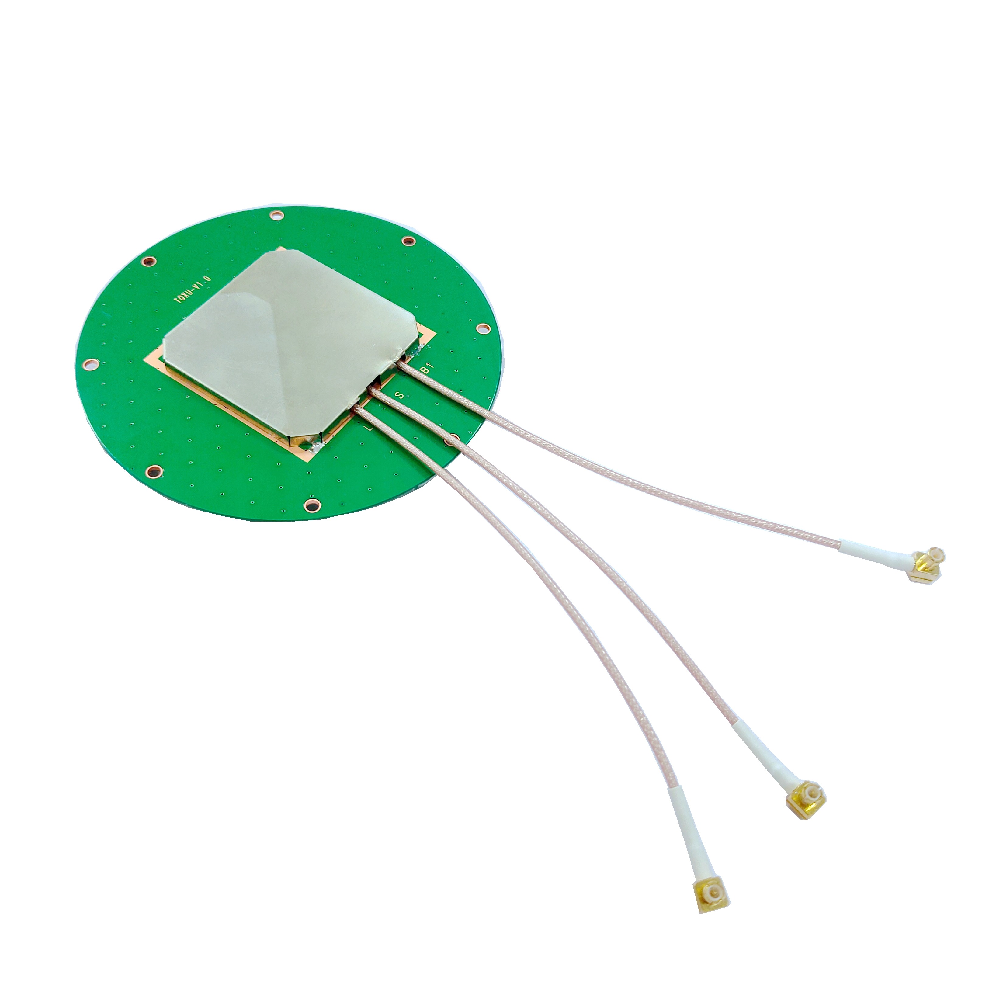
The design and construction of a portable GNSS survey antenna are a masterclass in electromagnetic engineering, materials science, and practical ergonomics. Every element, from the external radome to the internal feed network, is meticulously crafted to achieve a singular goal: the pristine acquisition of L-band satellite signals. The architecture can be broken down into several key components, each serving a distinct and vital function.
1. The Radiating Element: The Antenna Core
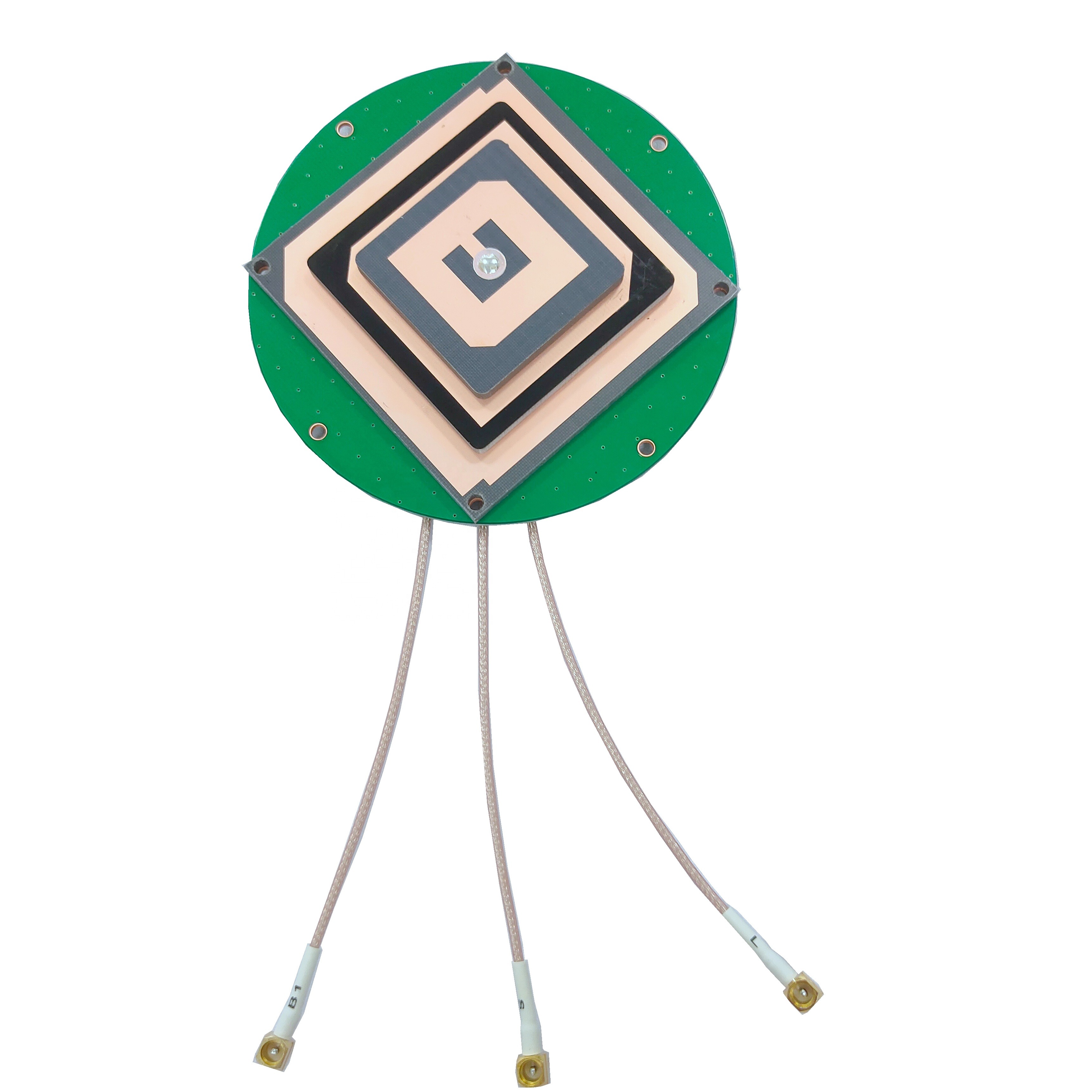
At the heart of every GNSS antenna is the radiating element, responsible for converting electromagnetic waves into electrical currents and vice-versa. For survey-grade antennas, the most common type is a patched antenna or a quadrifilar helix antenna (QHA).
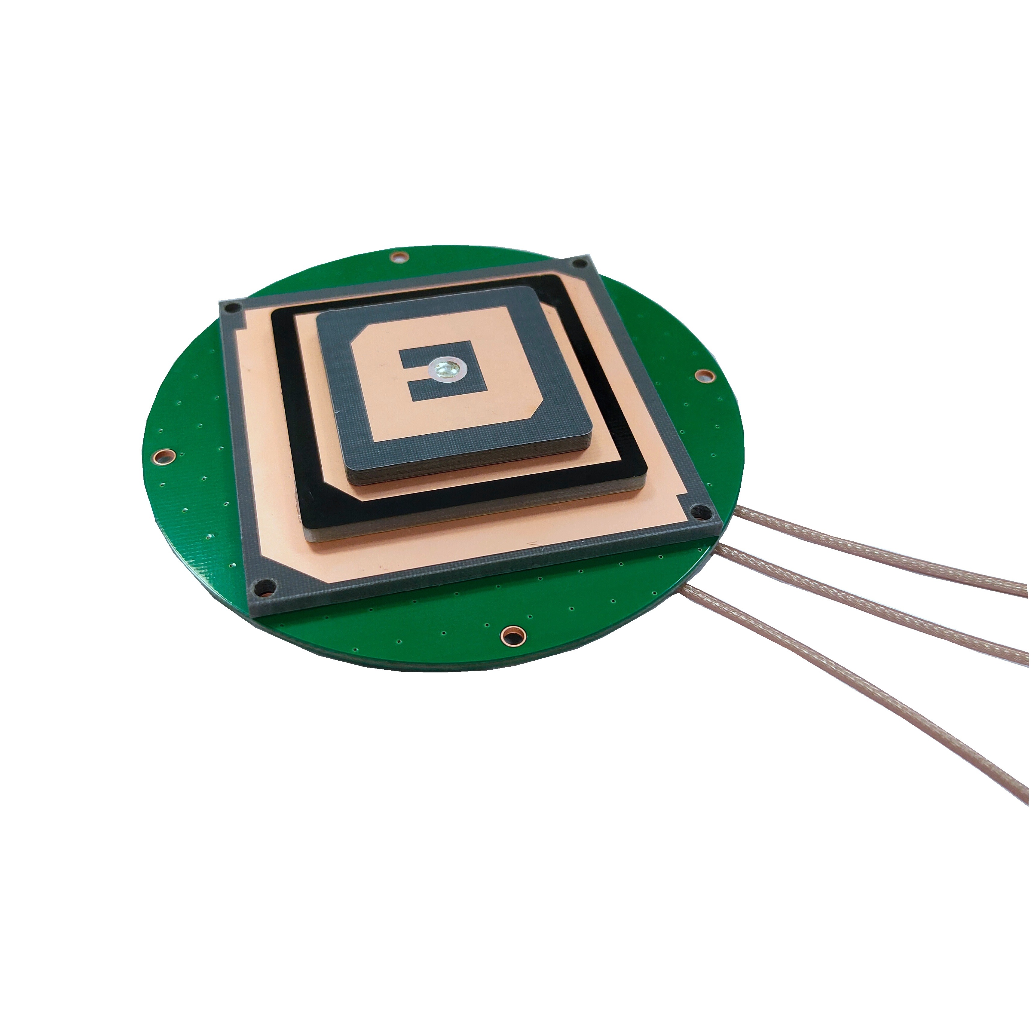
Patch Antennas: These are the most prevalent in portable designs. They consist of a metallic patch (often circular or square) printed on a dielectric substrate, positioned over a ground plane. Their advantages include a low profile, ruggedness, ease of manufacturing, and a well-defined hemispherical radiation pattern ideal for receiving signals from the horizon to the zenith. Modern designs often use a stacked-patch approach, where multiple patches are layered to resonate at different GNSS frequencies (e.g., L1, L2, L5).
Quadrifilar Helix Antennas (QHA): These are made of four helical arms fed in quadrature phase. They typically offer a slightly wider bandwidth and a more symmetrical radiation pattern than patch antennas, which can be beneficial for mitigating multipath from low-elevation angles. They are often housed in a cylindrical radome.
2. The Ground Plane
The ground plane is a critical conductive surface located beneath the radiating element. It serves multiple purposes: it defines the antenna's radiation pattern, directing energy upward towards the sky; it provides a stable electrical reference point; and it acts as a shield, blocking interference and noise from below the antenna. In portable antennas, the ground plane is often a circular or square metal plate. Its size and shape are carefully calculated to optimize the antenna's gain pattern and phase center stability.
3. The Feed Network and Balun
The feed network is the circuitry that transfers the energy from the radiating element to the output cable. For antennas with multiple elements (like a stacked patch), this network includes power dividers and phase shifters to ensure signals combine correctly. A crucial component within this network is the balun (balanced-to-unbalanced transformer). GNSS signals are balanced, but the coaxial output cable is an unbalanced transmission line. The balun ensures efficient power transfer between the two and prevents unwanted currents from flowing on the outside of the cable shield, which can act as a secondary antenna and introduce noise and multipath.
4. The Radome
The radome is the external protective cover, typically made of a low-loss dielectric material like plastic or ceramic. Its primary function is to protect the delicate internal components from physical damage, water, dust, and UV radiation. However, its design is far from simple. The radome must be electromagnetically transparent at GNSS frequencies. Its shape, thickness, and material properties are engineered to minimize signal reflection, attenuation, and phase distortion. A poorly designed radome can significantly degrade the antenna's performance.
5. The Choke Ring (Often Integrated or Optional)
Many high-end portable survey antennas incorporate a choke ring mechanism, either as an integrated base or as a removable accessory. A choke ring is a series of concentric, corrugated metal rings surrounding the antenna. It works as a ground plane extension that is highly effective at suppressing multipath. It creates a high impedance for signals arriving at low angles (which are likely reflected), causing them to be rejected, while allowing high-angle direct signals to pass unimpeded. This is a hallmark feature of geodetic-grade antennas.
6. The Low-Noise Amplifier (LNA)
GNSS signals are incredibly weak by the time they travel over 20,000 km to reach the Earth's surface. The LNA is an active electronic component integrated into the antenna body whose job is to amplify these faint signals before they are sent down the coaxial cable to the receiver. This is vital because any loss in the cable would amplify the signal-to-noise ratio degradation. The LNA must have very high gain but introduce minimal internal electrical noise itself (a characteristic measured by its noise figure). It is usually powered by the receiver through the center conductor of the coaxial cable via phantom power.
7. Filters
Built-in bandpass filters are often included to reject out-of-band interference. These filters allow the desired GNSS frequencies (e.g., ~1176 MHz for L5, ~1227 MHz for L2, ~1575 MHz for L1) to pass through while attenuating strong signals from cellular networks, radio, and TV broadcasts that could overload the sensitive LNA and receiver.
Materials and Portability: The entire assembly is housed in a rugged, weatherproof casing, often made from materials like ABS plastic or aluminum. The design prioritizes a low weight (typically 500 grams to 1.5 kg) and a compact form factor for easy transport and mounting on a tripod or pole. Connectors, typically TNC or N-type for robustness, are sealed to prevent moisture ingress. This holistic approach to design and construction ensures that the antenna is not just a passive collector but an active, intelligent front-end system dedicated to signal integrity.
The working principle of a portable GNSS survey antenna transcends the simple concept of "picking up a signal." It is an exercise in precision electromagnetism, focused on capturing the carrier wave of the satellite signal with an unprecedented level of phase stability, which is the key to centimeter-level accuracy.
Fundamental Reception: At its most basic, the antenna operates on the principle of electromagnetic induction. The metallic radiating element (the patch or helix) is cut to a specific physical length to resonate at the target GNSS frequencies (e.g., L1 at 1575.42 MHz). As the weak, right-hand circularly polarized (RHCP) electromagnetic waves from the satellites pass through this element, they induce a tiny, oscillating electrical current within it. This current is an analog representation of the satellite signal, containing the ranging codes (C/A-code, P-code) and the navigation message, all modulated onto the underlying L-band carrier wave.
The Critical Importance of Phase Stability: For standard positioning, the receiver uses the transmitted codes to calculate the time of flight and thus the distance (pseudorange) to the satellite. However, for survey-grade precision, the primary observable is the phase of the carrier wave itself. The carrier wave has a much shorter wavelength (~19 cm for L1) compared to the code chips (~300m for C/A-code). Measuring the phase of this wave is akin to using a much finer ruler, allowing for millimeter-scale measurements. The antenna's single most important job is to ensure that the phase of the signal is not distorted as it is received and amplified.
This is where the concept of the Phase Center becomes paramount. The phase center is the hypothetical point in space from which the signal appears to emanate. For a perfect antenna, this point would be fixed and consistent for all frequencies and all directions of incoming signals. In reality, it varies slightly. A high-quality survey antenna is engineered to have a stable and well-calibrated phase center. Its physical symmetry, ground plane, and internal design minimize how much this point moves as a satellite moves across the sky (azimuth and elevation) or when different frequencies are used. Any uncalibrated movement of the phase center translates directly into a positional error. Manufacturers provide precise phase center variation (PCV) models that receivers use to correct for these tiny, predictable offsets.
Multipath Mitigation: The antenna is the first line of defense against multipath error. It combats this through several mechanisms:
Radiation Pattern: Its gain is highest towards the zenith (directly overhead) and lowest towards the horizon. Since direct signals come from above and reflected signals often come from low angles, this pattern naturally attenuates multipath.
Right-Hand Circular Polarization (RHCP): GNSS satellites transmit RHCP signals. When a signal reflects off a surface, its polarization often reverses to become primarily left-hand circularly polarized (LHCP). The antenna is designed to be highly sensitive to RHCP and reject LHCP signals, thus filtering out many reflections.
Ground Plane and Choke Rings: As described in the design section, these structures prevent signals from arriving from below the antenna horizon, which are almost exclusively multipath.
Signal Amplification and Transmission: The tiny induced currents, representing the signal, are passed through the feed network to the Low-Noise Amplifier (LNA). The LNA boosts the signal strength by up to 40 dB while adding the absolute minimum amount of internal electronic noise. This amplified signal is then sent down the coaxial cable to the receiver. The active nature of the antenna (powered by the receiver) means the signal is strong enough to overcome cable losses, ensuring a healthy signal-to-noise ratio (SNR) arrives at the receiver for processing.
In summary, the working principle is not passive reception but active preservation. The antenna acts as a precision filter and amplifier, designed to faithfully capture the phase of the carrier wave from direct signals only, reject noise and reflections, and deliver a clean, stable, and powerful signal to the receiver, providing the highest quality raw data for the complex differential positioning algorithms to work their magic.
Portable GNSS survey antennas are enabling tools for high-precision applications, but their use comes with a set of distinct advantages and inherent challenges that practitioners must understand.
Advantages:
Unparalleled Accuracy: The primary advantage is the ability to achieve centimeter-to-millimeter level positioning in real-time (RTK/PPK) or post-processing. This accuracy is fundamental to modern surveying, engineering, and construction projects where error margins are极小.
High Reliability and Availability: By being multi-constellation (GPS, GLONASS, Galileo, BeiDou) and multi-frequency, these antennas can receive signals from dozens of satellites simultaneously. This drastically improves performance in "challenging environments" like urban canyons, under tree canopy, and in deep valleys by ensuring enough satellites are always in view to compute a fixed solution.
Robust Multipath Rejection: Integrated features like advanced ground planes, choke rings, and RHCP filtering give these antennas a significant advantage over consumer-grade alternatives in environments prone to reflections, such as near buildings or vehicles.
Portability and Deployment Speed: Their lightweight, rugged, and self-contained design allows a single surveyor to quickly set up a base station or use a rover antenna on a pole. This mobility drastically increases fieldwork efficiency compared to traditional static surveying methods or large, fixed-base antennas.
Resilience to Interference: Built-in filters and sophisticated design make them more resistant to jamming and radio frequency interference (RFI) from other electronic devices, which is increasingly important in crowded spectral environments.
Global Reference Frame Compatibility: The stable phase center and calibrated performance ensure that measurements are consistent and tied into global geodetic reference frames (like ITRF), which is essential for large-scale projects and scientific applications.
Challenges:
Cost: High-precision engineering, specialized materials, and rigorous calibration processes make portable GNSS survey antennas significantly more expensive than consumer-grade models, often representing a major investment for a surveying outfit.
Calibration and Phase Center Knowledge: To achieve their stated accuracy, the antenna's Phase Center Variations (PCV) must be precisely calibrated by the manufacturer and the correct model must be applied within the receiver's processing software. Using an incorrect or outdated model can introduce systematic errors of several centimeters.
Precise Setup and Orientation: For the PCV model to be valid, the antenna must be correctly set up. It must be accurately leveled and oriented (if it's a directional antenna). Even a slight tilt can introduce a measurable error, especially in height. The use of a tripod with a optical plummet or a bipod with a precise level bubble is mandatory.
Power Dependency: As active antennas, they require power from the receiver. A failure in the power supply (e.g., a faulty cable or dead battery) will result in a complete loss of signal, as the LNA will not function.
Environmental Limitations: While they perform well in challenging conditions, no antenna is immune to extreme multipath or signal blockage. Dense foliage, operating inside, or next to large reflective surfaces can still degrade performance or prevent a fixed solution altogether, requiring supplementary surveying techniques.
Physical Vulnerability: Despite being rugged, they are precision instruments. A significant impact can misalign internal components, damage the radome, or affect the ground plane, altering its electromagnetic properties and degrading performance in ways that may not be immediately obvious but will affect accuracy.
Cable Integrity: The coaxial cable is a critical part of the system. Damage to the cable, or using a low-quality cable with high signal loss, can degrade the signal-to-noise ratio, negatively impacting performance. Connectors are also potential points of failure if not properly maintained.
Understanding these advantages and challenges is key to selecting the right antenna for a project and employing it correctly in the field to ensure data quality and project success.
The applications of portable GNSS survey antennas are vast and growing, permeating every industry that requires precise knowledge of location on Earth. Simultaneously, the technology continues to evolve, driven by new satellite signals and emerging user needs.
Applications:
Classical Surveying and Mapping: This remains the core application. Surveyors use these antennas for cadastral mapping (property boundaries), topographic surveys, construction staking, and engineering projects for roads, bridges, and tunnels. They enable rapid and highly accurate data collection.
Construction and Machine Control: They are used to establish accurate project control networks. Furthermore, they are mounted on earthmoving equipment (bulldozers, graders, excavators) in systems that use RTK to guide blades and buckets to the exact design grade in real-time, drastically reducing rework and saving time and fuel.
Precision Agriculture: Farmers use GNSS rovers for soil sampling, yield mapping, and guiding tractors for planting, spraying, and fertilizing. This allows for variable-rate application (VRA), applying inputs only where needed, which increases yields, reduces costs, and minimizes environmental impact.
Scientific Research: Geologists use them to monitor tectonic plate motion and volcanic deformation. Glaciologists track the movement and thinning of ice sheets. Environmental scientists map erosion, wetland boundaries, and wildlife habitats. The stability and accuracy are key for long-term monitoring studies.
Unmanned Aerial Vehicles (UAVs / Drones): A portable antenna is a key component of a PPK/RTK-enabled drone. It provides the precise positioning needed for the drone to fly accurate survey patterns and to geotag aerial imagery without the need for numerous ground control points, streamlining the photogrammetry process for creating high-accuracy orthomosaics and 3D models.
Autonomous Vehicles and Robotics: While still emerging, the high-precision positioning provided by these antennas is a foundational technology for the development and testing of autonomous vehicles for farming, mining, and eventually public roads, as well as for mobile robots in logistics and industry.
Asset Management and Utilities: For mapping underground utilities, cell tower locations, and other critical infrastructure, ensuring that records are accurate and tied to a precise geographic coordinate system.
Future Trends:
Multi-Frequency, Multi-Constellation as Standard: The trend is towards antennas that natively and optimally support all current and planned signals: GPS L1C, L2C, L5; Galileo E1, E5a, E5b, E6; BeiDou B1, B2, B3; GLONASS L1, L2, L3. This will further improve availability, speed of integer ambiguity resolution, and robustness.
Integrated Inertial Navigation Systems (INS): We are seeing the emergence of antennas with built-in Inertial Measurement Units (IMUs—gyroscopes and accelerometers). This deep integration creates a single, tightly coupled navigation solution that provides continuous positioning even during short GNSS outages (e.g., under bridges or in tunnels), which is critical for mobile mapping and autonomous systems.
Enhanced Multipath Mitigation: Research continues into even more effective multipath mitigation techniques, including advanced adaptive filtering within the antenna's electronics and more sophisticated choke ring and ground plane designs using metamaterials.
Resilience to Interference and Jamming: As the RF environment becomes noisier, future antennas will incorporate more advanced adaptive null-steering capabilities to automatically identify and nullify sources of jamming or interference, a critical need for safety-critical applications.
Miniaturization and Reduced Power Consumption: The drive for smaller, lighter, and more power-efficient designs will continue, especially for integration into drones, wearable devices, and the Internet of Things (IoT) for precision agriculture and environmental sensing.
AI-Enhanced Calibration and Operation: Artificial intelligence could be used to create dynamic, real-time phase center and multipath correction models that adapt to the immediate environment of the antenna, moving beyond static calibration models.
Low-Earth Orbit (LEO) Satellite Signal Reception: Some companies are proposing navigation from LEO satellite constellations (e.g., Starlink). Future antennas may be designed to also receive and process these signals, which could be stronger and more robust than traditional GNSS, potentially revolutionizing high-precision positioning once again.
The portable GNSS survey antenna will remain a vital sensor, evolving from a specialized geomatic tool into a core component of a wide array of automated and intelligent systems that will define the future of many industries.
Conclusion
The portable GNSS survey antenna is a masterpiece of specialized engineering that sits at the very beginning of the high-precision positioning data chain. It is far more than a simple passive receiver; it is an active, intelligent system designed for one paramount objective: the flawless acquisition of the carrier phase of GNSS signals. Its value is not in its complexity for the user, but in its ability to perform its duty with such consistency and fidelity that it becomes an invisible enabler of accuracy.
Through its sophisticated design—featuring a stable radiating element, a precise ground plane, a protective radome, and an integral low-noise amplifier—it tackles the fundamental enemies of GNSS accuracy: weak signals, multipath interference, and electronic noise. Its ability to receive multiple frequencies from multiple constellations simultaneously has transformed field operations, providing unprecedented reliability and availability of precise positioning across the globe.
While challenges remain, such as the need for precise calibration, careful setup, and managing costs, the advantages it offers are undeniable. It has been the key catalyst for efficiency gains in surveying, construction, and agriculture, and is now becoming a foundational technology for the next wave of autonomous systems and scientific discovery. As GNSS constellations continue to evolve and new signals come online, the antenna will continue to adapt, incorporating new technologies like integrated inertial navigation and advanced interference mitigation.
In conclusion, the portable GNSS survey antenna is a testament to the fact that true precision is built from the ground up—or rather, from the sky down. It ensures that the first step in the positioning process, the capture of the signal, is done with the highest possible integrity, providing the solid foundation upon which all subsequent digital processing and complex algorithms can reliably deliver centimeter-level accuracy. It is, and will remain, an indispensable tool for mapping our world and building our future.

 86 0755 2819 9597
Lucy Yang | lucy.y@toxutech.com
Nicole Li | nicole@toxutech.com
Dotty Zhao | sales04@toxutech.com
Global Business Director / Sales Team / Global Operations


 En
En Cn
Cn Korean
 Home >


