

-
Products -PCBA Manufacturing RF Connectors RF Cable Assemblys Embedded Antennas External Antennas Positioning Chips and Modules
RF Connectors

RF Cable Assemblys
Embedded Antennas
External Antennas
Positioning Chips and Modules


 Language


Language


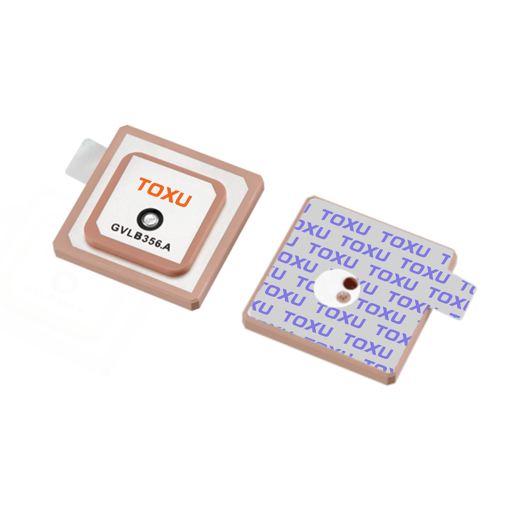
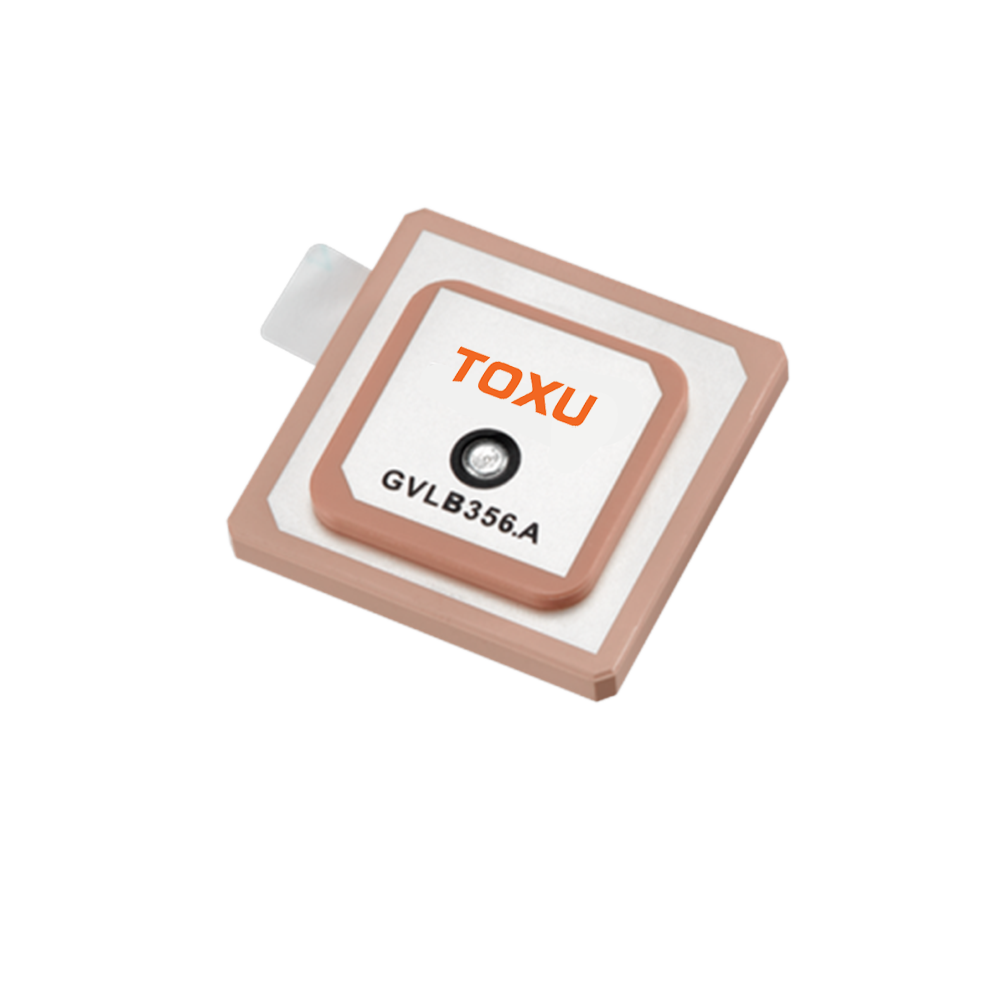

In the realm of high-precision positioning, the passive RTK (Real-Time Kinematic) GPS ceramic antenna stands as a critical component, bridging the gap between satellite signals and accurate location data. As the demand for centimeter-level positioning continues to surge across industries such as surveying, agriculture, construction, and autonomous robotics, understanding the nuances of this specialized antenna becomes essential. Unlike active antennas that integrate a low-noise amplifier (LNA) within the housing, passive RTK GPS ceramic antennas rely on external amplification to boost the weak satellite signals they receive. This design choice offers unique advantages in terms of flexibility, cost, and integration, making them a preferred option in applications where space constraints and system customization are paramount.
Ceramic antennas, in general, have long been favored for their compact size, robust performance, and cost-effectiveness. The ceramic material, typically a high-dielectric constant (high-εr) ceramic substrate, plays a pivotal role in enhancing the antenna's efficiency by reducing the wavelength of the incoming signals, allowing for a smaller form factor without significant loss in performance. When combined with RTK technology, which enables real-time positioning with centimeter-level accuracy by leveraging corrections from a base station, the passive ceramic antenna becomes a powerful tool in precision navigation systems.
This article will delve into the technical specifications, design considerations, performance characteristics, applications, and maintenance of passive RTK GPS ceramic antennas, providing a comprehensive overview of their role in modern high-precision positioning systems.
2.1 Frequency Range: Versatility Across Satellite Constellations
The passive RTK GPS ceramic antenna is designed to operate across multiple frequency bands, ensuring compatibility with various global navigation satellite systems (GNSS). As specified, its frequency range includes 1176 MHz and 1575 MHz, which correspond to key bands used by major GNSS constellations:
GPS: The 1575 MHz frequency aligns with the GPS L1 band, which is the primary civilian band for GPS. Additionally, the 1176 MHz frequency corresponds to the GPS L5 band, a newer band introduced to enhance accuracy and reliability, particularly in challenging environments. The L5 band offers better resistance to interference and multipath effects, making it valuable for RTK applications where precision is critical.
BDS (BeiDou Navigation Satellite System): The antenna's frequency range also covers the B1 band (around 1561 MHz) and B2 band (around 1176 MHz) of China's BeiDou system. This compatibility ensures that the antenna can leverage signals from BeiDou satellites, increasing the number of available satellites and improving positioning accuracy, especially in regions where BeiDou coverage is strong.
The ability to operate across these frequency bands is crucial for RTK performance. By receiving signals from multiple bands and satellite constellations, the antenna reduces the risk of signal loss due to interference or blockage, ensuring a more robust and reliable positioning solution. This multi-frequency capability also allows for better correction of ionospheric delays, a major source of positioning error, by comparing signals at different frequencies.
2.2 Gain: Balancing Signal Reception and Directionality
Gain is a key parameter that measures the antenna's ability to amplify incoming signals in a specific direction. The passive RTK GPS ceramic antenna offers a gain of 3.4 dBi at 1176 MHz and 5 dBi at 1575 MHz. These values are carefully optimized to balance signal reception with directionality, ensuring efficient capture of satellite signals while minimizing noise and interference.
At 1575 MHz (GPS L1 band), the higher gain of 5 dBi is beneficial for capturing the relatively stronger signals from GPS satellites, which are widely used in civilian applications. This higher gain helps in environments where signals may be weakened by obstacles such as trees or buildings, ensuring that the antenna can still receive sufficient signal strength for accurate positioning.
At 1176 MHz (GPS L5 and BDS B2 bands), the slightly lower gain of 3.4 dBi is a result of the antenna's design optimization for these specific bands. While the gain is lower, the L5 and B2 bands offer inherent advantages in terms of signal quality, such as wider bandwidth and better resistance to interference, which compensate for the lower gain. The balance between gain and frequency response ensures that the antenna performs consistently across all supported bands, a critical factor for RTK systems that rely on multi-frequency data for precise corrections.
2.3 Polarization: RHCP for Optimal Satellite Signal Reception
Polarization refers to the orientation of the electric field of the transmitted signal. Satellite signals are typically right-hand circularly polarized (RHCP), which is why the passive RTK GPS ceramic antenna is designed with RHCP polarization. This matching ensures maximum signal reception efficiency, as RHCP antennas are highly effective at capturing RHCP signals from satellites.
Circular polarization is particularly important in satellite communication because the orientation of the satellite relative to the receiver can change due to satellite movement and atmospheric effects. Unlike linear polarization, which is sensitive to orientation, circular polarization maintains signal strength regardless of the angle between the antenna and the satellite. This makes RHCP an ideal choice for GPS and GNSS antennas, ensuring consistent signal reception even as the satellite's position changes.
In some cases, the antenna may also offer linear polarization as an option, but this is less common in RTK applications. Linear polarization is more susceptible to signal degradation due to orientation changes and multipath interference, making RHCP the preferred choice for high-precision positioning systems.
2.4 VSWR: Ensuring Efficient Signal Transmission
Voltage Standing Wave Ratio (VSWR) is a measure of how efficiently the antenna transmits or receives signals. A VSWR of 1.5, as specified for this antenna, indicates excellent impedance matching between the antenna and the coaxial cable (which has a characteristic impedance of 50 ohms). A VSWR of 1.5 means that only a small portion of the signal is reflected back towards the source, with the majority being transmitted or received by the antenna.
Efficient impedance matching is critical for passive antennas because they lack an internal LNA to compensate for signal losses. Any reflection due to poor VSWR would result in reduced signal strength, which can degrade the performance of the RTK system. A low VSWR ensures that the maximum amount of signal is transferred between the antenna and the receiver, minimizing losses and maximizing the signal-to-noise ratio (SNR) – a key factor in achieving centimeter-level positioning accuracy.
2.5 Input Impedance: Compatibility with System Components
The input impedance of the passive RTK GPS ceramic antenna is specified as 50 ohms, which is the standard impedance for most RF (radio frequency) systems, including GPS receivers and coaxial cables. This standardization ensures compatibility with a wide range of system components, from coaxial connectors to external LNAs and receivers.
Matching the antenna's impedance to the rest of the system is essential for minimizing signal reflections and maximizing power transfer. A mismatch would result in signal loss, reduced SNR, and potentially increased noise, all of which can compromise the accuracy of the RTK positioning. By adhering to the 50-ohm standard, the antenna can be easily integrated into existing RTK systems without the need for additional impedance-matching components, simplifying the design and reducing costs.
2.6 Coaxial Connectors and Cables: Ensuring Reliable Signal Path
The passive RTK GPS ceramic antenna offers a range of coaxial connector options, including SMA, MCX, MMCX, HRS, and IPX. These connectors are widely used in RF applications and provide secure, low-loss connections between the antenna and the coaxial cable. The choice of connector depends on the specific application requirements, such as space constraints, durability, and ease of installation.
SMA connectors are robust and commonly used in applications where a secure connection is needed, such as in outdoor equipment.
MCX and MMCX connectors are smaller, making them ideal for compact devices where space is limited, such as drones or small robotic systems.
HRS and IPX connectors are often used in high-volume, consumer electronics applications due to their ease of assembly and compact size.
The antenna is also compatible with various coaxial cable types, including RF1.78, RF1.37, RF1.13, and RF0.81. These cables differ in diameter, flexibility, and signal loss characteristics. Thicker cables (such as RF1.78) offer lower signal loss over longer distances, making them suitable for applications where the antenna is mounted far from the receiver. Thinner cables (such as RF0.81) are more flexible and compact, ideal for tight spaces but may exhibit higher loss over longer lengths. The choice of cable depends on the specific installation requirements, balancing signal integrity with physical constraints.
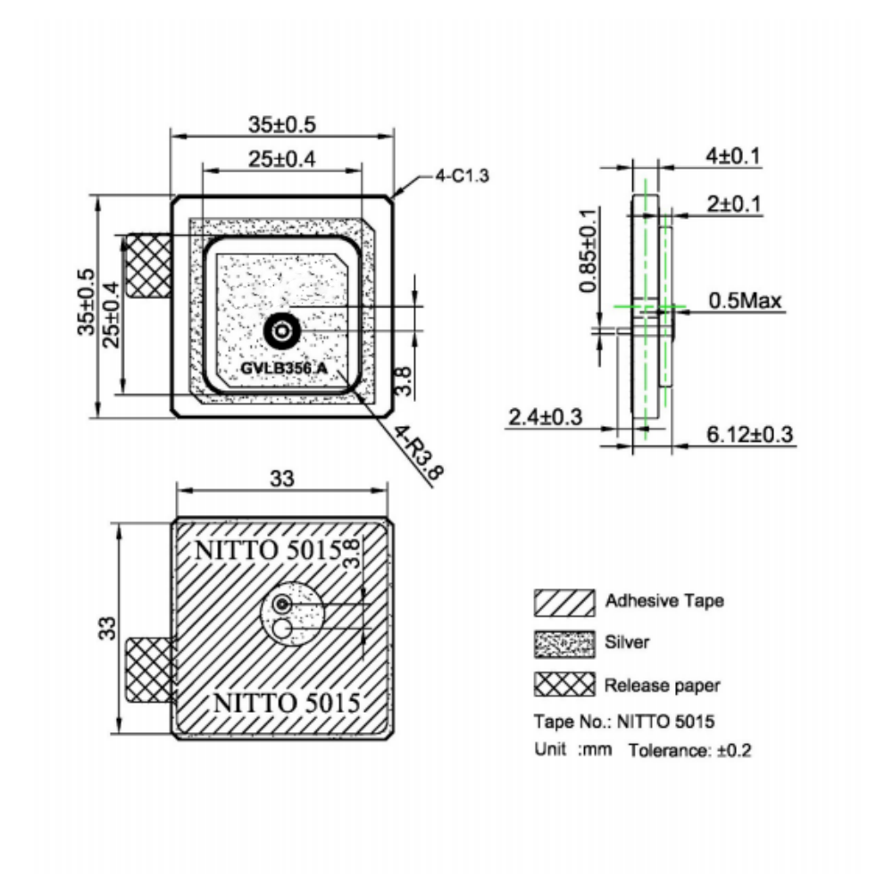
2.7 Dimensions and DC Voltage: Compact Design and Power Considerations
The PCB (printed circuit board) dimension of the antenna is 70x70mm, a compact size that makes it suitable for integration into a wide range of devices, from surveying equipment to autonomous drones. The small form factor is achieved through the use of high-dielectric ceramic material, which allows the antenna to resonate at the required frequencies without the need for large physical dimensions.
While the antenna itself is passive and does not require power to operate, the external LNA and receiver system typically require a DC voltage of 3~5V. This voltage is often supplied through the coaxial cable using a bias tee, which separates the DC power from the RF signal. Ensuring a stable power supply within this range is crucial for the proper operation of the external components, as voltage fluctuations can affect the performance of the LNA and, consequently, the overall system accuracy.
3.1 Ceramic Substrate Selection: The Foundation of Performance
The choice of ceramic substrate is critical to the performance of the passive RTK GPS ceramic antenna. High-dielectric constant (high-εr) ceramics, such as barium titanate (BaTiO3) based materials, are commonly used due to their ability to reduce the wavelength of the RF signals. This wavelength reduction allows the antenna to achieve resonance at the desired frequencies (1176 MHz and 1575 MHz) in a smaller physical size, which is essential for compact applications.
The dielectric constant of the ceramic material is carefully selected based on the target frequencies. A higher dielectric constant results in a smaller antenna size but may also lead to higher losses if not properly optimized. Manufacturers balance the dielectric constant with other material properties, such as loss tangent (a measure of energy loss in the material), to ensure that the antenna maintains high efficiency while remaining compact.
The ceramic substrate is typically fabricated using advanced ceramic processing techniques, such as sintering, to achieve the desired dielectric properties. The sintering process involves heating the ceramic material to high temperatures, causing the particles to bond together and form a dense, uniform structure. This ensures consistent dielectric performance across the substrate, which is essential for maintaining uniform antenna gain and radiation patterns.
3.2 Radiating Element Design: Optimizing for Multi-Frequency Operation
The radiating element of the passive RTK GPS ceramic antenna is typically a metallic patch printed on the ceramic substrate using techniques such as screen printing or photolithography. The shape and dimensions of the patch are carefully designed to resonate at the target frequencies (1176 MHz and 1575 MHz).
For multi-frequency operation, the patch may be designed with slots or notches to create additional resonant frequencies. Alternatively, a stacked patch design, where multiple patches are layered on top of each other, can be used to achieve resonance at multiple frequencies. Each patch is optimized for a specific frequency band, ensuring that the antenna maintains high gain and efficiency across all supported bands.
The design of the radiating element also takes into account the polarization requirement (RHCP). This is achieved through the use of a circular patch or a linear patch with a feed network that introduces a 90-degree phase shift between orthogonal components of the signal, creating a circularly polarized wave. The feed point of the patch is carefully positioned to ensure proper impedance matching (50 ohms) and to maximize the antenna's gain in the desired direction (towards the sky, where satellites are located).
3.3 Ground Plane Considerations: Enhancing Radiation Patterns
The ground plane is a critical component of the passive RTK GPS ceramic antenna, as it helps to shape the radiation pattern and improve the antenna's efficiency. The ground plane is typically a metallic layer (such as copper) printed on the opposite side of the ceramic substrate from the radiating element.
For a GPS antenna, the ideal radiation pattern is a hemispherical pattern that radiates primarily upwards, towards the satellites. The ground plane helps to suppress radiation in the downward direction, focusing the antenna's energy towards the sky. This improves the antenna's gain in the desired direction and reduces interference from signals reflected off the ground or nearby objects (multipath interference).
The size of the ground plane is also important. A larger ground plane can improve the antenna's radiation pattern and gain, but it increases the overall size of the antenna. For the 70x70mm PCB dimension specified, the ground plane is typically designed to match the size of the PCB, balancing performance with compactness. In some cases, the ground plane may be extended beyond the PCB using additional metallic layers or structures, but this is dependent on the specific application requirements.
3.4 Manufacturing Quality Control: Ensuring Consistency and Reliability
The manufacturing process of passive RTK GPS ceramic antennas involves strict quality control measures to ensure consistent performance across units. Each antenna undergoes rigorous testing to verify its electrical specifications, including frequency response, gain, VSWR, and polarization.
Testing is typically performed using an anechoic chamber, which is a shielded room designed to eliminate reflections of RF signals. In the anechoic chamber, the antenna is mounted on a turntable, and a test antenna is used to transmit signals at the target frequencies. The received signal strength and pattern are measured as the turntable rotates, allowing for the characterization of the antenna's radiation pattern and gain.
VSWR testing is performed using a network analyzer, which measures the reflection coefficient of the antenna. This ensures that the antenna's input impedance is within the specified 50-ohm range and that the VSWR is 1.5 or lower. Polarization testing is also conducted to verify that the antenna exhibits RHCP, ensuring optimal reception of satellite signals.
In addition to electrical testing, the antenna's mechanical properties are checked to ensure durability and reliability. This includes testing for resistance to temperature extremes, humidity, vibration, and shock – environmental factors that can affect performance in outdoor applications such as surveying or construction.
4.1 Multipath Rejection: Mitigating Signal Reflections
Multipath interference is a major challenge in GPS positioning, occurring when satellite signals are reflected off nearby objects (such as buildings, trees, or the ground) before reaching the antenna. These reflected signals can cause errors in the time-of-arrival measurements used to calculate position, degrading accuracy.
Passive RTK GPS ceramic antennas are designed to minimize the impact of multipath interference through several mechanisms:
Radiation Pattern Optimization: The hemispherical radiation pattern, enhanced by the ground plane, reduces the antenna's sensitivity to signals coming from low angles (near the horizon), which are more likely to be reflected. This focuses the antenna's reception on direct signals from high-angle satellites, which are less prone to multipath.
Circular Polarization (RHCP): Reflected signals often undergo a polarization reversal (becoming left-hand circularly polarized, LHCP), making them less detectable by an RHCP antenna. This inherent rejection of LHCP signals helps to reduce multipath errors.
Ceramic Material Properties: The high-dielectric ceramic substrate helps to minimize signal loss and improve the antenna's selectivity, reducing the impact of unwanted reflected signals.
While passive antennas do not include active multipath mitigation techniques (such as those found in some active antennas with built-in signal processing), their design characteristics make them effective at reducing multipath interference in many RTK applications.
4.2 Signal-to-Noise Ratio (SNR): Critical for RTK Accuracy
The SNR is a measure of the strength of the desired satellite signal relative to the background noise. A high SNR is essential for RTK systems, as it enables the receiver to accurately decode the satellite signals and apply the RTK corrections, resulting in centimeter-level positioning.
The passive RTK GPS ceramic antenna contributes to a high SNR through its optimized gain and low-loss design. The antenna's gain (3.4 dBi at 1176 MHz and 5 dBi at 1575 MHz) amplifies the weak satellite signals, while the low VSWR (1.5) ensures minimal signal loss between the antenna and the receiver. The use of high-quality ceramic materials with low loss tangent also helps to minimize signal attenuation within the antenna itself.
However, because the antenna is passive, it relies on an external LNA to further boost the signal and reduce noise. The LNA is typically placed close to the antenna to minimize cable losses, which can significantly degrade SNR. The combination of the antenna's high gain and the LNA's low noise figure ensures that the overall system maintains a high SNR, even in challenging environments where satellite signals are weak.
4.3 Phase Center Stability: Ensuring Precise Positioning
The phase center of an antenna is the point from which the antenna appears to receive signals, and it is critical for accurate positioning. Variations in the phase center (phase center variation, PCV) with changes in signal direction (azimuth and elevation) can introduce errors in the measured position, which is particularly problematic for RTK systems requiring centimeter-level accuracy.
Passive RTK GPS ceramic antennas are designed with tight phase center stability. The use of a uniform ceramic substrate and a carefully designed radiating element ensures that the phase center remains consistent across different signal angles. Manufacturers often characterize the PCV of their antennas through rigorous testing, providing calibration data that can be used by RTK receivers to correct for any remaining variations.
Phase center stability is especially important in applications such as surveying, where the antenna's position is measured relative to a fixed point. Even small variations in the phase center can accumulate over distance, leading to significant positioning errors. By maintaining a stable phase center, the passive RTK GPS ceramic antenna ensures that the RTK system can achieve the required level of accuracy.
In terms of applications, passive GPS ceramic antennas find use in a diverse array of fields. In the automotive industry, they are integrated into in-dash navigation systems, providing real-time positioning data to drivers. Their compact size and low power consumption make them suitable for this application, where space is limited and energy efficiency is important. In aviation, these antennas contribute to auxiliary navigation systems, leveraging their multi-band support to enhance positioning accuracy and reliability, particularly in conjunction with other navigation technologies.
Maritime navigation also benefits from passive GPS ceramic antennas, as their durability and resistance to moisture make them well-suited for installation on boats and ships. The ability to operate across multiple GNSS bands ensures that vessels can maintain accurate positioning even in remote oceanic regions where satellite coverage may vary. In agriculture, these antennas are used in precision farming equipment, such as GPS-guided tractors and harvesters, enabling precise field mapping and crop management.
The IoT sector is another major user of passive GPS ceramic antennas. They are integrated into asset trackers, allowing businesses to monitor the location of shipments, vehicles, and equipment in real time. Their small size and low power consumption make them ideal for wearable devices, such as fitness trackers and smartwatches, which require compact components and long battery life. In addition, passive GPS ceramic antennas are used in smart city applications, such as traffic management systems and waste collection optimization, where accurate positioning data is essential for efficient operation.
Despite their many advantages, passive GPS ceramic antennas do have limitations. Their lack of built-in amplifiers means that they may struggle to receive weak signals in environments with heavy interference, such as urban canyons or dense foliage. In such cases, active antennas with amplifiers may be more suitable. However, for many applications where signal conditions are moderate, passive antennas offer a compelling balance of performance, cost, and efficiency.
In conclusion, the passive GPS ceramic antenna is a versatile and reliable component that plays a crucial role in modern positioning and navigation systems. Its broad frequency coverage, optimized gain, flexible polarization options, and compatibility with various connectors and cables make it suitable for a wide range of applications, from consumer electronics to industrial and automotive systems. The use of high-quality ceramic materials and a compact PCB design ensures durability, efficiency, and ease of integration, while its passive nature delivers power savings and cost benefits. As GPS and GNSS technologies continue to evolve, the passive GPS ceramic antenna will remain a key enabler of accurate, reliable, and accessible positioning solutions across industries.

 86 0755 2819 9597
Lucy Yang | lucy.y@toxutech.com
Nicole Li | nicole@toxutech.com
Dotty Zhao | sales04@toxutech.com
Global Business Director / Sales Team / Global Operations


 En
En Cn
Cn Korean
 Home >


