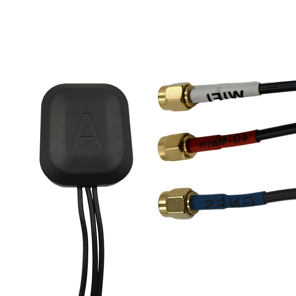
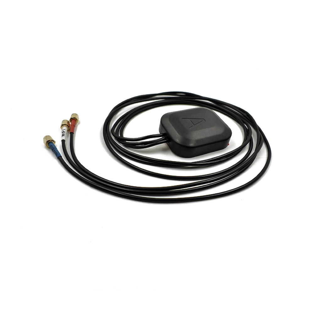
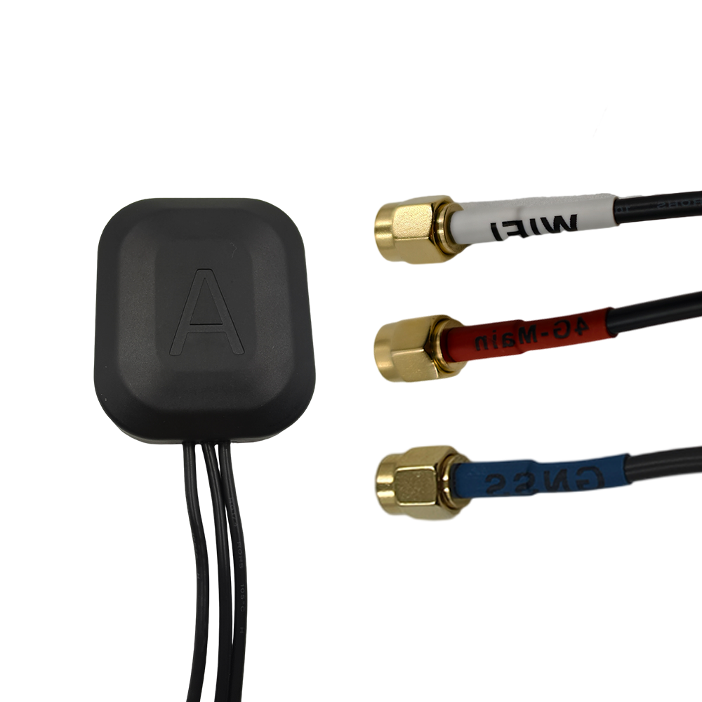
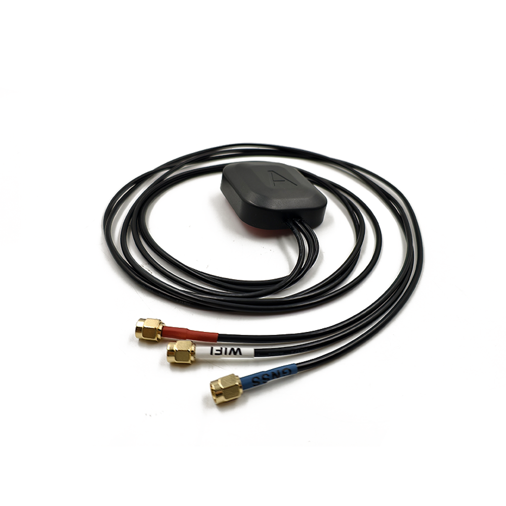
overview
An Outdoor High-Gain RTK Antenna is a ruggedized, high-performance antenna defined by its application environment, its electrical characteristics, and its purpose:
Outdoor: This signifies a product built for permanent or long-term deployment in harsh environmental conditions. It is engineered to withstand relentless UV exposure, wide temperature fluctuations (-40°C to +85°C), driving rain, humidity, ice, and wind load. Its construction is defined by resilience and long-term operational stability.
High-Gain: This is a measure of the antenna's ability to direct radio frequency energy in a preferred direction. A high-gain antenna (typically in the range of 26 dB to 35 dB) doesn't create power; it focuses it. It achieves this by having a narrower, more directed beamwidth that concentrates its sensitivity towards the sky, maximizing the signal strength from satellites above the horizon while rejecting noise and low-angle interference.
RTK: This designation means the antenna is specifically designed for carrier-phase-based positioning. Its paramount characteristics are an extremely stable phase center and superior multipath mitigation. Unlike code-based navigation antennas, an RTK antenna must provide a measurement quality that allows the receiver to resolve integer ambiguities quickly and maintain a fixed, centimeter-accurate solution.
The primary driver for this technology is the need for reliable, continuous, and precise positioning in challenging operational environments. While lower-grade antennas may suffice in open-sky conditions, real-world applications like precision agriculture, construction, surveying, and scientific monitoring often involve less-than-ideal settings. The high-gain RTK antenna is the tool of choice when operating near trees, buildings, or other obstacles that can partially obscure the sky and introduce multipath error—the phenomenon where signals bounce off surfaces before arriving at the antenna, causing significant positioning errors.
These antennas are the workhorses of critical infrastructure. They are deployed as permanent reference stations in Continuously Operating Reference Station (CORS) networks, providing the correction data that enables RTK for an entire region. They are mounted on agricultural machinery guiding autonomous tractors through vast fields, on construction equipment ensuring grade control to millimeter precision, and on monitoring systems tracking the subtle movement of dams, bridges, and volcanoes.
Therefore, the outdoor high-gain RTK antenna represents the fusion of robust mechanical engineering and electromagnetic excellence. It is the unsung hero that operates silently in the background, often in remote locations, providing the trustworthy data that underpins modern high-stakes geospatial science, engineering, and commerce. Its value is measured not in its cost, but in the reliability of the data it provides and the cost of the errors it prevents.
Design and Construction
The design and construction of an outdoor high-gain RTK antenna is a meticulous process that balances the need for unparalleled electrical performance with the requirement to survive decades of exposure to the elements. Every material, layer, and mechanical detail is chosen to ensure signal integrity and long-term reliability.
1. The Radiating Element: The Heart of Precision
At the core lies the radiating element, which is almost invariably a patched antenna design.
Multi-Frequency Design: Modern RTK antennas are dual or triple-frequency, capable of receiving signals from the L1, L2, and L5 bands of all major GNSS constellations (GPS, GLONASS, Galileo, BeiDou). This is achieved through a stacked-patch configuration, where multiple patches of carefully calculated dimensions are layered. A larger patch is tuned for lower frequencies (e.g., L2), while a smaller upper patch is tuned for higher frequencies (e.g., L1). This allows for efficient operation across a wide bandwidth.
Materials: The patches are printed on low-loss dielectric substrates or fused onto ceramic materials. The use of low-loss materials is critical to ensure that a maximum amount of energy is radiated rather than dissipated as heat within the antenna itself.
2. The Choke Ring Ground Plane: The Multipath Nullifier
The most distinctive feature of a high-end RTK antenna is the choke ring assembly. This is not a mere aesthetic choice; it is the antenna's primary weapon against multipath error.
Function: The choke rings are concentric, corrugated channels machined into a metal base. The depth of these channels is precisely calculated to be approximately one-quarter of the wavelength of the target GNSS frequencies.
Mechanism: For signals arriving at low angles (which are typically multipath reflections), the choke rings present a high-impedance surface. This prevents surface currents from flowing, effectively making the ground plane "invisible" to these unwanted signals. The choke rings "choke" off the multipath, allowing only the desired direct line-of-sight signals from satellites at higher elevations to pass through to the radiating element.
3. The Low-Noise Amplifier (LNA): Preserving Signal Integrity
Located immediately after the radiating element is a high-quality, ruggedized Low-Noise Amplifier (LNA).
High Gain and Low Noise Figure: The LNA provides significant gain (30-40 dB) to boost the incredibly weak satellite signals. Crucially, it has an extremely low noise figure (often < 2 dB), meaning it adds minimal electronic noise of its own during amplification. This preserves the signal-to-noise ratio (SNR), which is essential for the receiver to maintain lock on the carrier phase.
Filtering: The LNA stage includes sophisticated bandpass filtering to reject strong out-of-band interference from cellular, radio, and other communication systems that are ubiquitous in the environment.
4. Phase Center Stability: The Non-Negotiable Metric
For RTK, the stability of the antenna's Phase Center—the virtual point from which the radiation appears to emanate—is the single most important electrical characteristic.
Design Symmetry: The entire internal assembly is designed for perfect electromagnetic symmetry. This ensures the phase center remains stable regardless of the azimuth or elevation angle of the incoming satellite signal.
Calibration: Each antenna model is meticulously calibrated in an anechoic chamber. This process maps the precise Phase Center Offset (PCO) and Phase Center Variation (PCV) for every frequency band. This calibration data is applied in the post-processing software or receiver firmware to correct measurements to a single, stable virtual point, enabling millimeter-level accuracy.
5. Environmental Sealing and Ruggedized Housing
The "outdoor" designation is earned through brutal environmental testing.
Radome: The protective radome is made from high-impact, UV-stabilized polycarbonate or fiberglass. It is designed to be RF-transparent and to withstand physical impact from hail or debris.
Sealing: The unit is hermetically sealed to IP66 or IP67 standards, using high-quality silicone gaskets and O-rings to prevent the ingress of moisture and dust. The internal electronics are often potted with a waterproof, thermally conductive epoxy to protect against condensation, corrosion, and vibration.
Mounting: The base features a standard geodetic mounting thread (typically 5/8"-11) for secure attachment to a permanent monument, tripod, or pole. The housing and internal components are made from materials with matching thermal expansion coefficients to prevent stress and sealing failures over temperature cycles.
In summary, the construction of an outdoor high-gain RTK antenna is a holistic process of creating a sealed, fortified instrument. It is designed to protect its delicate internal precision from a hostile world, guaranteeing that its electrical performance remains consistent and reliable year after year.
Working Principles
The operation of an outdoor high-gain RTK antenna is a sophisticated process of spatial filtering, signal purification, and amplification. It functions not as a simple collector of signals, but as a highly selective curator of the electromagnetic environment, ensuring that only the most valuable data—the direct satellite signals—are passed to the receiver.
1. Spatial Filtering via Directivity and Gain
The antenna's high gain is achieved through directivity. Unlike an omnidirectional antenna, it focuses its sensitivity into a narrower beamwidth, primarily towards the zenith (directly overhead).
Beamwidth: A high-gain antenna might have a beamwidth of 70-90 degrees, compared to over 120 degrees for a standard antenna. This means it is most sensitive to satellites high in the sky.
The Effect: Satellites at higher elevations provide stronger, cleaner signals as they pass through less of the Earth's atmosphere. By favoring these satellites and attenuating signals from low-elevation satellites (which are weaker, noisier, and more susceptible to atmospheric delays and multipath), the antenna provides the receiver with a higher-quality set of observations from which to calculate a position.
2. Multipath Mitigation: The Choke Ring's Role
The choke rings are the cornerstone of its signal purification. They create an artificial horizon.
Quarter-Wave Trap: Each ring acts as a quarter-wave trap for a specific frequency. A signal traveling across the corrugations encounters a high impedance, preventing surface currents from flowing.
Rejecting Low-Angle Noise: This mechanism effectively rejects signals arriving from at or below the horizontal plane. Since multipath reflections from the ground, buildings, and other obstacles always arrive at low angles, they are dramatically attenuated before they can ever reach the radiating element and corrupt the measurement.
3. Phase-Stable Signal Path for Carrier-Phase Tracking
The entire mechanical and electrical design is optimized for one goal: enabling precise carrier-phase measurement. The receiver measures the phase of the satellite's carrier wave itself, which allows for millimeter-level accuracy.
Stable Electrical Point: The symmetrical, rigid construction ensures that the electrical path length from the antenna's reference point to its phase center is constant. It does not change with temperature, satellite direction, or weather.
Calibration Application: The predetermined calibration model (PCO/PCV) is applied in the processing software. This corrects the raw measurements for the tiny, predictable variations in the phase center, ensuring all data is referenced to a single, stable virtual point. This stability is mandatory for the receiver to resolve the integer wavelength ambiguities quickly and reliably.
4. Low-Noise Amplification: Boosting the Whisper
The faint signals that pass through the antenna's spatial and choke ring filters are amplified by the LNA. Its high gain ensures the signal is strong enough to travel down long cables to the receiver without being degraded by cable loss. Its low noise figure is critical; it boosts the signal without adding significant noise, preserving the high SNR needed for the receiver to maintain a stable lock on the carrier phase, which is easily broken by noise.
5. Multi-Constellation, Multi-Frequency Support
The antenna simultaneously receives signals from all available satellites and all frequencies. This provides redundancy, improves satellite geometry (lowering PDOP), and enables advanced error correction. For example, using the phase difference between the L1 and L2 frequencies allows the receiver to model and remove ionospheric delay, a major source of error.
In essence, the outdoor high-gain antenna works by acting as a vigilant guardian at the edge of the system. It uses physics to create a privileged window to the sky, admitting only the purest direct signals and providing the GNSS receiver with the highest-quality data possible from which to calculate a supremely accurate and reliable position.
Advantages and Challenges
-
Deploying an outdoor high-gain RTK antenna offers a compelling set of advantages for mission-critical applications, but these benefits come with a distinct set of challenges and cost implications that must be carefully evaluated.
Advantages:
Unmatched Multipath Rejection: This is the paramount advantage. The choke ring design provides best-in-class suppression of reflected signals, which is the dominant source of error in precision GNSS. This directly translates to higher measurement accuracy and reliability.
Ultra-Stable Phase Center: The massive, symmetrical, and rigid construction ensures that the antenna's electrical phase center remains constant over time, temperature, and for signals from any direction. This stability is the absolute foundation for achieving millimeter-level precision.
Superior Signal-to-Noise Ratio (SNR): The combination of high gain and a low-noise amplifier results in excellent SNR. This allows for faster satellite acquisition, more reliable tracking in electrically noisy environments, and the ability to maintain a lock under weaker signal conditions (e.g., mild foliage).
Environmental Ruggedness: Built to withstand decades of outdoor exposure, these antennas offer unparalleled operational longevity and mean time between failures (MTBF), reducing downtime and maintenance costs for permanent installations.
Calibration and Traceability: High-end models come with individualized absolute phase center calibration certificates. This allows for the highest level of measurement correction and ensures consistency across different sites and networks.
Challenges:
High Cost: The precision machining, extensive materials, rigorous testing, and calibration process make these antennas a significant investment, often costing thousands of dollars per unit.
Large Size and Weight: The choke ring assembly is necessarily large (often 30-40 cm in diameter) and heavy. This makes the antenna bulky and unsuitable for portable applications or platforms with strict size and weight constraints (e.g., small drones).
Narrower View of the Sky: The high directivity that provides the gain also means the antenna has a narrower beamwidth. It is optimized for satellites above roughly 15-20 degrees elevation. In severely obstructed environments (e.g., deep urban canyons), losing these low-elevation satellites can sometimes reduce the satellite count unacceptably, though this is often compensated for by the multi-constellation capability.
Complexity of Deployment: Using this antenna is not simple. It requires:
Careful Mounting: It must be mounted on a extremely stable and permanent monument to prevent any movement.
Precise Alignment: It must be leveled perfectly.
External Power: The LNA requires power, supplied by the receiver via the coaxial cable.
Overkill for Most Applications: The exceptional performance is simply not required for general navigation, GIS data collection, or asset tracking. Using it for these applications would be economically inefficient.
In conclusion, the advantages of an outdoor high-gain antenna—primarily unparalleled multipath rejection and phase stability—make it indispensable for scientific, geodetic, and industrial applications where accuracy is paramount. However, its size, cost, and operational complexity firmly relegate it to a niche market of high-precision professionals.
Applications and Future Trends
-
Outdoor high-gain RTK antennas are the enabling technology for a wide array of applications where data integrity and precision directly impact safety, efficiency, and scientific understanding.
Applications:
CORS Reference Stations: Forming the backbone of national and regional positioning infrastructure, providing real-time correction data for surveyors and engineers over a wide area.
Precision Agriculture: Used on autonomous tractors and harvesters and as fixed base stations for RTK networks guiding entire fleets of farming equipment. Multipath rejection is critical in open fields where ground reflections can occur.
Construction and Machine Control: Ensuring bulldozers, graders, and excavators achieve and maintain grade to within centimeters. The ruggedness is essential on dirty, vibrating job sites.
Structural and Geohazard Monitoring: Permanently installed on dams, bridges, volcanoes, and landslide areas to detect millimeter-level movements over time. Long-term reliability and stability are non-negotiable.
Scientific Research: Used in geodesy to measure tectonic plate motion, post-glacial rebound, and other geophysical phenomena.
Unmanned Aerial Vehicle (UAV) Surveying: As a ground-based base station for drone mapping missions, providing the precise reference point that allows drone-borne cameras and LiDAR to create accurate maps and models without ground control points.
Future Trends:
Full Multi-GNSS and Multi-Band Support: Evolution to fully support all signals from all constellations (GPS, GLONASS, Galileo, BeiDou, QZSS, IRNSS) and all frequencies (L1, L2, L5, L6) for maximum robustness and advanced error modeling.
Integrated Inertial Navigation Systems (INS): Tighter coupling with high-grade IMUs within the antenna housing to provide continuous positioning and orientation solutions during short GNOS outages.
Enhanced Resilience to Interference: Incorporation of advanced filtering and nulling techniques to detect and mitigate jamming and spoofing, which are growing threats to GNSS integrity.
Remote Monitoring and Diagnostics: Antennas will become "smart," with the ability to monitor their own health (e.g., cable integrity, LNA performance) and report status remotely via network connections.
Miniaturization of Performance: Research into artificial magnetic conductors (AMCs) and other metamaterials to achieve similar multipath rejection properties in a lower-profile package for applications where full choke rings are not feasible.
PPP-RTK Support: The ultra-stable characteristics of these antennas make them ideal reference stations for Precise Point Positioning (PPP) and PPP-RTK services, which aim to provide global centimeter-level accuracy without a local base station.
The future of the outdoor high-gain antenna is one of greater integration, smarter functionality, and enhanced resilience, cementing its role as the trusted source of truth for position in the most demanding applications.
Conclusion
The outdoor high-gain RTK antenna is far more than a component; it is a foundational pillar of modern high-precision geomatics. It represents the point where the theoretical potential of GNSS meets the practical requirement for reliable, centimeter-accurate data in the real world. Its design philosophy is one of uncompromising excellence, where signal integrity and mechanical fortitude are prioritized above all else.
Its value is measured not in its unit cost, but in its contribution to data quality, operational efficiency, and safety. The investment in such an antenna is an investment in certainty—the certainty that the positional data underpinning a construction project, a agricultural operation, or a scientific study is trustworthy. It is the difference between data that is "good enough" and data that is definitively correct.
However, this capability demands respect. It is a tool for experts who understand the importance of proper installation, calibration, and integration. Its performance is the reward for this expertise. It is not a solution for every GNSS application, but for those at the pinnacle of the precision market, it is an indispensable one.
Looking forward, its role will only become more critical. As autonomous systems become more prevalent and the need for precise positioning expands, the demand for resilient, reliable, and high-integrity GNSS data will be absolute. The outdoor high-gain RTK antenna, with its proven technology and continuous evolution, will remain the gold standard, the unwavering foundation upon which the most critical positioning applications are built. It is the silent sentinel that ensures our measurements of the Earth are, and remain, truly dependable.


 Language
 En
En Cn
Cn Korean

 Home >


 18665803017 (Macro)


