

-
Products -PCBA Manufacturing RF Connectors RF Cable Assemblys Embedded Antennas External Antennas Positioning Chips and Modules
RF Connectors

RF Cable Assemblys
Embedded Antennas
External Antennas
Positioning Chips and Modules


 Language


Language


In the precise and demanding world of Unmanned Aerial Vehicle (UAV) operations, particularly in mapping, surveying, and precision agriculture, the GNSS antenna is not merely a component; it is the fundamental sensor that defines the vehicle's understanding of its place in the world. An omni-directional GNSS UAV antenna is a specialized variant designed to fulfill this role under the unique and dynamic conditions of flight. Its core mission is to provide a continuous, reliable, and centimeter-accurate positional reference, regardless of the aircraft's attitude—its pitch, roll, or yaw. This "unblinking eye" to the satellite constellation is what transforms a UAV from a remotely piloted drone into an autonomous geospatial data collection platform.
The term "omni-directional" in this context requires precise definition. It does not mean perfectly spherical radiation; such an antenna is a physical impossibility. Instead, it describes an antenna with a wide, hemispherical radiation pattern that maintains strong gain across the entire upper hemisphere. This is fundamentally different from a ground-based antenna, which can afford to have a radiation pattern optimized primarily for the horizon and above, often sacrificing gain at lower elevations. A UAV, by contrast, is a dynamic platform. During aggressive maneuvers, banking turns, or when navigating uneven terrain, the antenna's "down" direction relative to the UAV's body can point towards the horizon or even partially towards the sky. A traditional antenna would risk losing lock on critical low-elevation satellites during such maneuvers. An omni-directional design ensures that even at high bank angles, there is always a sufficient portion of the antenna's pattern facing the sky to maintain a robust satellite lock.
This capability is the bedrock of several critical UAV functions. First and foremost, it enables high-quality Real-Time Kinematic (RTK) or Post-Processed Kinematic (PPK) positioning. By receiving signals from multiple Global Navigation Satellite Systems (GPS, GLONASS, Galileo, BeiDou) on multiple frequencies (L1, L2, L5, etc.), the antenna provides the raw data needed to resolve integer ambiguities and achieve centimeter-level accuracy. This precision is directly written into the geotags of each captured image, enabling the creation of highly accurate orthomosaics, digital surface models, and 3D point clouds with minimal ground control.
Furthermore, the omni-directional antenna is crucial for the UAV's flight controller and autopilot. It provides the primary source of absolute position and velocity data. A loss of GNSS signal, or a degradation in its quality, can trigger the vehicle to enter a less stable flight mode, abort its mission, or execute an emergency landing. The reliability afforded by an omni-directional pattern is therefore not just about data quality; it is a primary safety feature. It allows the UAV to operate confidently in complex flight paths, including BVLOS (Beyond Visual Line of Sight) missions, where continuous and trustworthy positioning is non-negotiable. In essence, this antenna is the silent guardian of both positional accuracy and flight safety, making it the indispensable navigational heart of any professional-grade UAV.
The design and construction of an omni-directional GNSS UAV antenna is a masterclass in balancing conflicting electromagnetic, mechanical, and operational demands. Every element is optimized for one goal: to maintain a stable and strong connection to the satellite constellation through the unpredictable movements of flight.
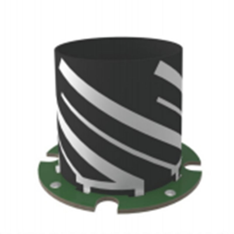
The most common and effective design for this application is the quadrifilar helix antenna (QHA) or its variant, the spiral helix. Unlike a flat patch antenna, which has a naturally directional pattern, the QHA is a three-dimensional structure consisting of four helices (or arms) wound cylindrically and fed with phases 90 degrees apart. This geometry is inherently suited to producing a cardioid or near-hemispherical radiation pattern with excellent right-hand circular polarization (RHCP) characteristics. Its gain is very consistent from the zenith (straight up) down to the horizon, with a smooth roll-off below the horizon to reject ground multipath. This pattern ensures that as the UAV banks, the effective gain towards the satellites remains stable, preventing sudden drops in signal strength that could cause loss of lock.
For smaller UAVs where a QHA might be too bulky, advanced stacked patch antennas are employed. However, a standard patch antenna's pattern is too directional. To achieve omni-directionality, designers use techniques like:
Multi-Feed Points: Feeding a single patch from multiple points to excite multiple modes and "smear" the radiation pattern into a more hemispherical shape.
Parasitic Elements: Placing additional resonant elements around the main patch to alter and broaden the pattern.
Cavity Backing: Using a shallow cavity behind the patch to control the pattern's rear lobes and improve front-to-back ratio.
Regardless of the radiating element type, multipath rejection remains a critical concern. A UAV's airframe—its carbon fiber arms, battery, camera gimbal, and payload—is a significant source of signal reflection. To combat this, the antenna is always mounted on a ground plane, typically a circular disc of aluminum. This ground plane serves to isolate the antenna from the noisy electronics below and pattern the energy upwards. For premium performance, Artificial Magnetic Conductors (AMCs) or metamaterial surfaces are integrated between the element and the ground plane. These periodic structures act as "high-impedance surfaces" that suppress surface waves and prevent radiation from being directed down into the UAV's body, thereby reducing multipath from the platform itself.
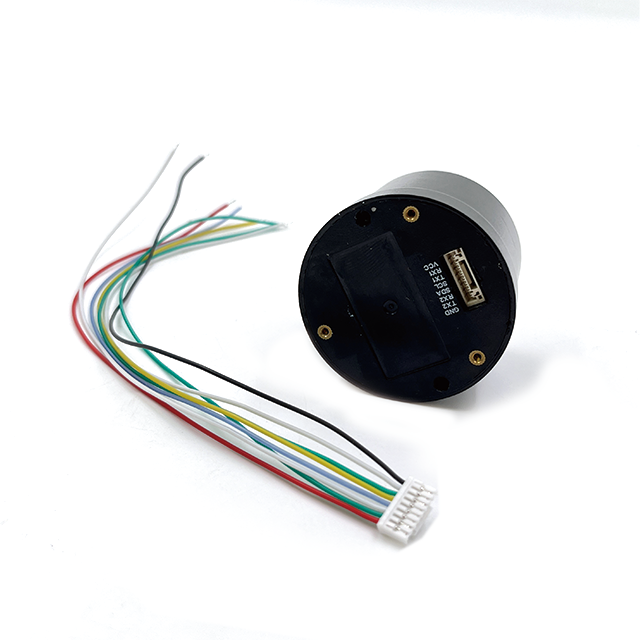
The Low-Noise Amplifier (LNA) is arguably as important as the antenna element itself. Located immediately after the radiating element, its job is to amplify the incredibly weak satellite signals (around -130 dBm) before any loss occurs. For UAV antennas, the LNA must have an ultra-low noise figure (often < 1.5 dB) to avoid adding hiss, and very high gain (typically 35-45 dB) to overcome the loss of the cable running to the receiver, which is often located inside the fuselage for protection. Crucially, it must include high-quality band-pass filters tuned precisely to GNSS frequencies. The UAV's environment is electrically noisy, with interference from motor controllers (ESCs), telemetry radios, and video transmitters. These filters are the first line of defense, preventing out-of-band interference from overloading the LNA and the downstream receiver.
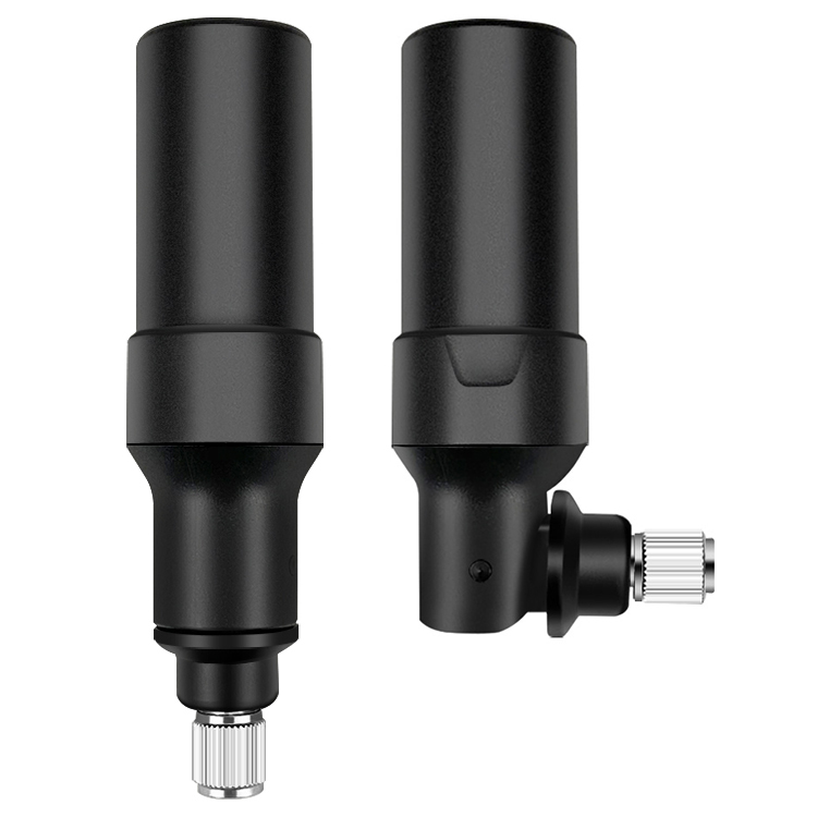
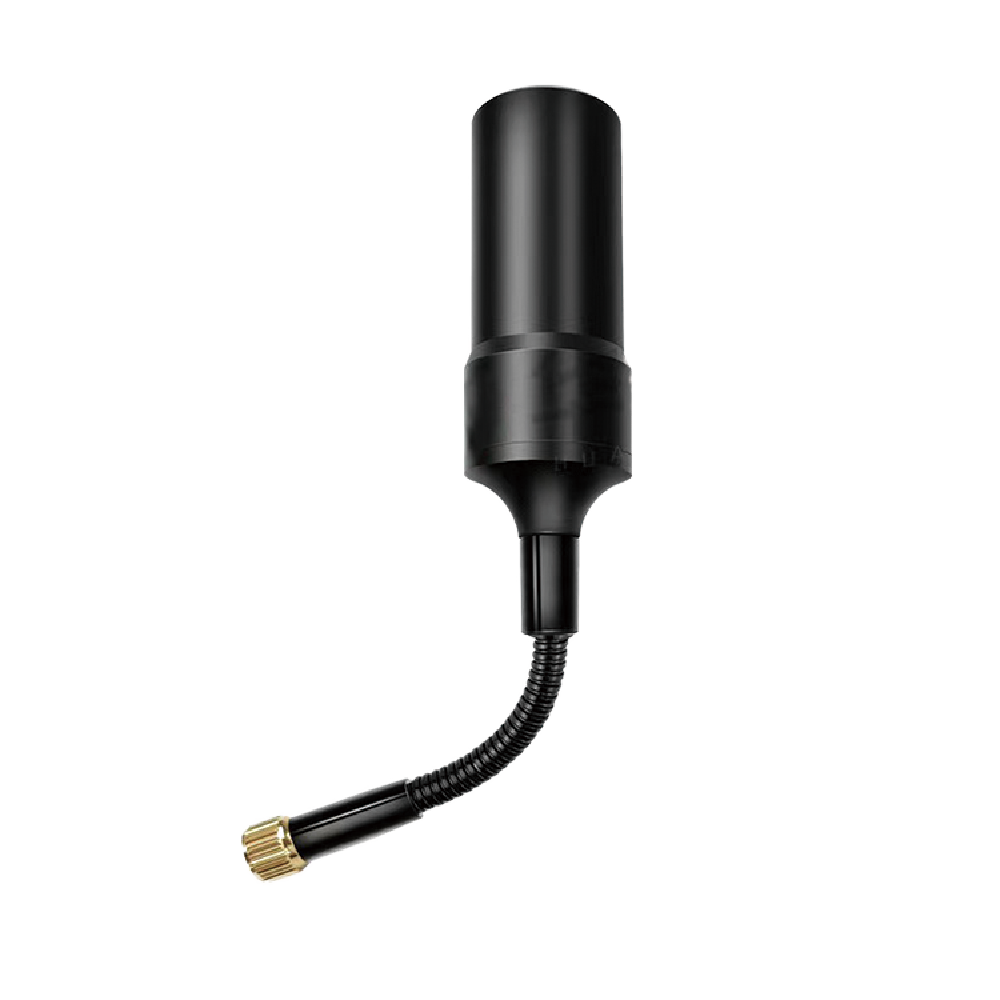
The physical construction is built for the rigors of flight. The entire assembly—element, ground plane, AMC, and LNA—is encased in a low-profile radome. This radome is made from RF-transparent materials like high-grade polycarbonate or ABS plastic, engineered to have minimal effect on the signal. It is aerodynamically shaped to reduce drag and is ruggedized to withstand wind pressure, vibration, and the occasional minor impact. The unit is hermetically sealed to IP67 or higher standards to prevent moisture ingress from rain, fog, or condensation, which would be catastrophic for performance.
Finally, the antenna features a robust mounting system, almost always utilizing the standard 5/8"-11 thread for secure attachment to a mast on the UAV's body or fuselage. This mast is itself a critical design element, raising the antenna above the propellers and the main airframe to minimize signal blockage and provide the clearest possible view of the sky, further enhancing its omni-directional capability.
The working principle of an omni-directional GNSS UAV antenna is defined by its need to perform in a constantly changing and challenging operational environment. Its function is to provide a stable and reliable electrical reference point—the phase center—while the platform it is mounted on moves violently through three-dimensional space.
The process begins with the antenna's radiation pattern. The carefully engineered hemispherical pattern ensures that a significant portion of its gain is always oriented towards the sky, regardless of the UAV's attitude. When the aircraft is in straight and level flight, the pattern is ideally aligned. When it banks at a 45-degree angle to turn, the pattern rotates with it. While the gain to satellites directly overhead may decrease slightly, the gain to satellites on the "high" side of the turn increases, and crucially, the antenna does not become blind to any section of the sky. This continuous coverage is what prevents satellite drop-outs during maneuvers.
As the RHCP signals from the satellites arrive, they induce currents in the antenna's elements (the helices of a QHA or the patches of a stacked design). The unique geometry of the QHA is particularly effective at preserving the purity of the signal's circular polarization, which helps to reject reflected signals that have reversed their polarization (LHCP), thus providing innate multipath rejection.
The tiny, induced signals are immediately amplified by the integrated LNA. This step is critical. The cable running from the antenna on its mast to the GNSS receiver inside the fuselage can be several feet long. Coaxial cable loss at 1.5 GHz is significant; a few feet of cable can attenuate the signal by 3-6 dB. Without the LNA's high gain, the signal would arrive at the receiver buried in the receiver's own thermal noise, making tracking impossible. The LNA elevates the signal well above this noise floor. Furthermore, its built-in filters strip away the powerful RF noise generated by the UAV's own systems, ensuring only the clean GNSS signals are amplified and sent down the cable.
The most critical aspect of the antenna's operation is phase center stability. For RTK/PPK to function, the electrical point from which the signals are measured must be immutably fixed relative to the UAV's body, specifically relative to the IMU (Inertial Measurement Unit). Any movement or vibration-induced shift of this electrical point is indistinguishable from an actual movement of the UAV to the receiver. The rigid mechanical construction of the antenna—bonding the element to the ground plane and sealing it within a solid radome—is designed to eliminate any such micro-movements. The antenna must be a rock-solid fiducial marker in space.
The receiver uses the clean, amplified signals from the antenna to perform carrier-phase tracking. The stability of the antenna's phase center ensures the "purity" of these phase measurements. During post-processing for PPK (or in real-time for RTK), this phase data is combined with data from a base station. The omni-directional pattern ensures that both the base and the rover (UAV) are tracking the same set of satellites continuously, which is a prerequisite for robust ambiguity resolution. Any loss of lock on a satellite due to pattern nulls would force the receiver to re-resolve the integer ambiguity for that satellite, potentially degrading the solution or causing a complete loss of fixed RTK status. The omni-directional antenna's role is to make this loss of lock a rare event, ensuring a continuous, high-integrity data stream for the navigation and mapping systems.
Integrating a high-quality omni-directional GNSS antenna onto a UAV provides transformative advantages for precision applications but introduces a distinct set of challenges that must be meticulously managed.
Advantages:
Continuous Satellite Tracking During Maneuvers: This is the paramount advantage. It enables complex flight plans with aggressive turns and banks without degradation of the GNSS solution, ensuring uninterrupted data collection and flight safety.
Enhanced Flight Safety and Reliability: The robust signal lock provided by the antenna is a primary safety feature. It prevents the UAV from entering less stable flight modes due to GNSS dropouts and is critical for enabling autonomous functions like return-to-home and precise hovering.
Improved Ambiguity Resolution for RTK/PPK: A stable view of a large number of satellites from any attitude allows the receiver to resolve the integer ambiguities more quickly and reliably. This leads to faster achievement of a fixed solution and a lower risk of integer fixes slipping during flight.
Reduced Multipath from Airframe: A well-designed antenna, particularly one using an AMC surface, patterns its energy away from the UAV's body. This actively suppresses multipath reflections generated by the airframe itself, a significant source of error for onboard antennas.
Superior Performance in Roll and Pitch: Unlike a patch antenna, which can suffer significant gain loss at high angles off-boresight, an omni-directional antenna maintains consistent performance, which is essential for mapping hilly or mountainous terrain where the UAV must constantly adjust its attitude to follow the ground.
Challenges and Limitations:
Size and Weight Penalty: Achieving a true hemispherical pattern often requires a more three-dimensional structure (like a QHA) than a simple patch, leading to a larger and heavier antenna. This can impact flight time and must be carefully factored into the UAV's payload budget.
Cost: The complex design, specialized materials (like AMCs), and the need for an ultra-high-performance LNA make omni-directional antennas significantly more expensive than basic patch antennas.
Integration and Placement Complexity: The antenna cannot be placed arbitrarily. It must be mounted on a mast to clear the propellers and airframe, which affects the UAV's aerodynamic profile and center of gravity. Furthermore, the precise lever arm—the 3D vector between the antenna's phase center and the IMU's origin—must be measured with millimeter accuracy. Any error in this measurement directly translates to a positional error in the final map.
Power Requirements: The high-gain LNA requires a source of DC power, typically provided from the receiver via the coaxial cable. The power system must be designed to supply this cleanly, without introducing noise.
Calibration Criticality: The antenna's phase center variations (PCV) must be well-characterized and accounted for. Using the antenna without its specific calibration file (in ANTEX format) can introduce several centimeters of systematic error into the positioning solution.
Vibration Sensitivity: While designed to be robust, extreme vibration can potentially affect the internal components or connections over time, though this is mitigated through potted electronics and solid construction.
The omni-directional GNSS antenna is the enabling technology for the most demanding and valuable UAV applications, where precision and reliability are paramount.
Applications:
Corridor Mapping: Mapping long, linear features like roads, railways, pipelines, and power lines requires the UAV to fly long, straight passes often with crosswinds that necessitate constant banking. The omni-directional antenna is essential for maintaining accuracy throughout these maneuvers.
PPK/RTK Aerial Surveying and Photogrammetry: For creating centimeter-accurate digital terrain models (DTMs) and orthomosaics for surveying, construction, and mining. The antenna ensures every image is accurately geotagged, enabling the reduction or elimination of ground control points.
Precision Agriculture: For missions like field mapping, crop health analysis, and variable-rate application (VRA) of inputs, where precise flight paths are necessary to avoid overlaps and gaps.
LiDAR and Mobile Mapping: UAV-based LiDAR systems are exceptionally sensitive to positional errors. The high-quality GNSS data from an omni-directional antenna, tightly coupled with an IMU, is critical for achieving the required point cloud accuracy.
BVLOS (Beyond Visual Line of Sight) Operations: Regulatory approval for BVLOS flights requires demonstrating extreme reliability in navigation. The robust GNSS performance provided by this antenna is a foundational element of the safety case.
Search and Rescue / Public Safety: Drones used in emergency response need to navigate complex environments and hold position reliably in windy conditions, all while providing accurate location data for found objects or persons.
Future Trends:
Tighter GNSS-IMU Integration: The future is moving towards fully integrated GNSS-Inertial Navigation Systems (GNSS-INS) where the antenna, receiver, and IMU are co-located in a single, factory-calibrated unit. This eliminates lever arm measurement errors and simplifies integration.
Multi-Antenna Systems for Heading: Using two omni-directional antennas on a UAV (a primary and a secondary) allows the system to calculate heading with extremely high precision based on the carrier-phase difference between them, providing a reliable heading source even when stationary.
Anti-Jamming and Anti-Spoofing (AJS): As airspace becomes more crowded and security concerns grow, future UAV antennas will incorporate advanced AJS capabilities, using controlled radiation pattern arrays (CRPAs) to nullify interfering or malicious signals.
L5/E5a/B2a Band Optimization: Future antennas will be specifically optimized for the new civilian signals (L5, E5a, B2a) which offer higher power, better multipath resistance, and improved ionospheric correction capabilities.
Further Miniaturization: Advances in metamaterials and ceramic substrates will allow for more compact omni-directional designs with performance equal to or better than today's larger antennas, enabling their use on smaller UAV platforms.
Conclusion
The omni-directional GNSS UAV antenna is far more than a simple receiver of satellite signals. It is a highly specialized, precision-engineered system that serves as the unwavering navigational heart of the modern professional UAV. It solves the fundamental problem of maintaining a continuous, high-integrity connection to the satellite constellation amidst the dynamic and electromagnetically noisy environment of an unmanned aircraft in flight.
Its value is measured not in its individual specifications, but in the capabilities it unlocks: the execution of complex flight paths, the collection of survey-grade geospatial data, and the assurance of operational safety. By providing a stable phase center and a resilient hemispherical view of the sky, it enables the centimeter-level accuracy that has revolutionized industries from agriculture to construction.
While it presents challenges in terms of cost, size, and integration, these are investments in reliability and data quality. The future of autonomous UAV flight, particularly in complex airspace and for BVLOS operations, is inextricably linked to the continued evolution of this critical technology. It is the silent, steadfast guardian of positional truth, the unblinking eye that allows drones to not only fly but to measure the world with unparalleled accuracy. In the journey towards fully autonomous aerial systems, the omni-directional GNSS antenna remains an indispensable and foundational enabler.

 86 0755 2819 9597
Lucy Yang | lucy.y@toxutech.com
Nicole Li | nicole@toxutech.com
Dotty Zhao | sales04@toxutech.com
Global Business Director / Sales Team / Global Operations


 En
En Cn
Cn Korean
 Home >


