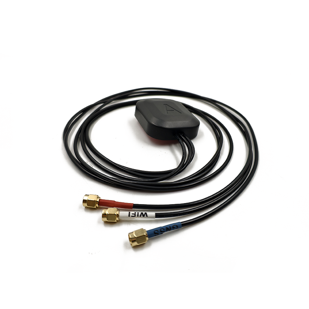
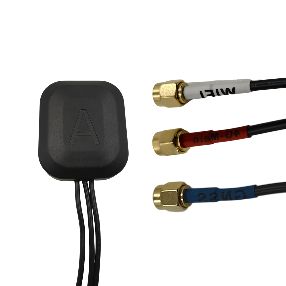
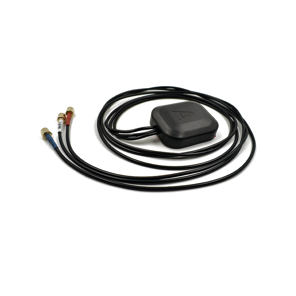
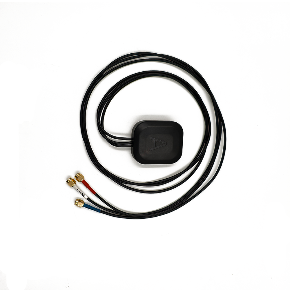
Combo Antenna Combo Antenna

Language
Built-in RTK GPS Antenna
GNSS Car Antenna
GNSS Car Antenna

GPS & GNSS Antenna

Home >  GPS & GNSS Antenna > 

Multi-frequency GNSS Antenna

The Global Navigation Satellite System (GNSS) landscape is undergoing a profound transformation, moving from an era dominated by a single constellation (GPS) on a single frequency (L1) to a new paradigm of multi-constellation, multi-frequency positioning. At the heart of this revolution is a critical yet often overlooked component: the multi-frequency GNSS antenna. This antenna is the essential gateway, the first element in the signal chain that enables the advanced capabilities of modern high-precision GNSS receivers, from robust RTK to centimeter-level autonomous positioning.


Leave a message Contact

Fill in your email address

Or you can continue to download without filling in

Overview

A multi-frequency GNSS antenna is specifically designed to receive and process satellite signals across multiple frequency bands from all available global and regional navigation satellite systems. This includes the core constellations: the American GPS, the Russian GLONASS, the European Galileo, and the Chinese BeiDou, along with augmentation systems like Japan's QZSS and India's NavIC. Unlike a simple single-band L1 antenna found in a smartphone or car navigation system, a multi-frequency antenna must be meticulously engineered to operate efficiently across a wide spectrum of frequencies, including but not limited to:

GPS: L1 C/A, L2C, L5

GLONASS: L1, L2, L3

Galileo: E1, E5a, E5b, E6

BeiDou: B1, B2, B3

The driving force behind the adoption of multi-frequency technology is the relentless pursuit of accuracy, reliability, and integrity. Single-frequency receivers are inherently limited. They must use complex models to estimate and correct for the signal delay caused by the Earth's ionospherea layer of the atmosphere filled with charged particles that can significantly slow down GNSS signals, introducing meters of error. These models are imperfect, and this ionospheric error remains the largest source of inaccuracy for standard GNSS.

Multi-frequency receivers overcome this fundamental limitation through a elegant physical principle: the ionospheric delay is dispersive, meaning it affects different frequencies differently. By measuring the same signal on two or more frequencies, the receiver can directly calculate the ionospheric delay and remove it almost completely from the measurement. This is known as the ionosphere-free combination. However, this capability is entirely dependent on the antenna's ability to cleanly receive these multiple frequencies simultaneously.

The benefits extend far beyond ionospheric correction. Multi-frequency operation is the key to:

Faster and More Reliable RTK: By providing more observables, multi-frequency data allows RTK engines to resolve the integer ambiguities much faster and maintain a "fixed" solution more robustly, even in moderately challenging environments.

Advanced Anti-Jamming and Anti-Spoofing: New civilian signals on bands like L5 and E6 are more powerful and have more sophisticated code structures, making them more resistant to interference and malicious spoofing attacks.

Improved Signal Tracking: The longer wavelength of L5/E5a signals allows receivers to recover from signal outages more quickly and provides better performance in urban canyons and under light foliage.

The multi-frequency antenna is what makes all of this possible. It is the front door to a richer, more robust, and more accurate dataset. Without an antenna capable of receiving these signals with high fidelity and minimal distortion, the most advanced multi-frequency receiver chipset would be rendered ineffective. Its design is a complex balancing act of electrical engineering, requiring broad bandwidth, stable phase response, consistent radiation patterns across all bands, and rigorous control over phase center variation.

From surveying and precision agriculture to autonomous vehicles and unmanned aerial systems, the multi-frequency antenna is becoming the new standard, enabling applications that demand uninterrupted, centimeter-level accuracy in real-time. It represents a critical evolution in GNSS technology, transforming it from a useful navigation tool into a high-reliability sensor for mission-critical systems.


Design and Construction

The design and construction of a multi-frequency GNSS antenna is a significant leap in complexity compared to a single-band antenna. It is no longer sufficient to optimize performance for a single center frequency; the design must achieve high performance across a wide swath of the radio spectrum, from approximately 1160 MHz to 1300 MHz and from 1550 MHz to 1610 MHz, while maintaining precise phase characteristics and a consistent radiation pattern. This requires sophisticated engineering and careful selection of materials and geometries.

Core Design Components and Techniques:

Radiating Element: The heart of the antenna is the radiating element, which is almost universally a patch antenna due to its low profile, ease of manufacture, and ability to produce hemispherical coverage. However, a standard circular or rectangular patch has a limited bandwidth (typically 1-3%), which is utterly insufficient for multi-frequency operation.

Bandwidth Enhancement Techniques: To achieve the required wideband or multi-band operation, antenna designers employ several advanced techniques:

Stacked Patches: This is the most common and effective technique for a multi-frequency geodetic antenna. It involves using two or more patch elements, stacked on top of each other and separated by dielectric layers. The larger, lower patch is tuned to the lower frequency band (e.g., L2/L5), while the smaller, top patch is tuned to the higher frequency band (e.g., L1). This design allows each patch to operate near its resonant frequency, providing good performance across both bands without excessive compromise.

Slot-Coupled Feed: Instead of directly probing the patch, the electromagnetic energy is coupled to it through a slot in the ground plane. This allows for better impedance matching and reduces spurious radiation from the feed network, which is crucial for maintaining a pure phase response.

Use of Low Permittivity Substrates: Using thick substrates with a low dielectric constant (εr) increases the bandwidth of a patch antenna. This is a fundamental trade-off: lower εr and greater height yield wider bandwidth but a physically larger antenna.

The Ground Plane: A solid, finite ground plane is essential beneath the patch. It serves to direct the antenna's sensitivity upwards (providing a hemispherical pattern) and shields it from multipath signals and noise emanating from below. The size of the ground plane directly influences the antenna's gain pattern, particularly its ability to reject low-elevation signals. A larger ground plane generally provides better multipath rejection at the horizon.

Feed Network and Impedance Matching: This is a critical subsystem. The feed network must deliver power from the single output cable to the radiating element(s) while maintaining a 50-ohm impedance match across all target frequencies. For stacked patches, this often involves a complex arrangement of feeds to excite each patch optimally. Any imperfection in the feed network can introduce losses and, more importantly, phase delays that vary with frequency, destroying the geometric integrity of the measurements.

Phase Center and Calibration: Perhaps the most critical aspect for high-precision applications is the stability of the antenna's Phase Center. The phase center is the electrical point from which the signal is received; it is the virtual reference point for all measurements. In a perfect antenna, the phase center would be a fixed point in space that does not move regardless of the direction (azimuth and elevation) of the incoming satellite signal.

Phase Center Offset (PCO): The vector difference between the antenna's physical reference point (often the ARP - Antenna Reference Point) and its average phase center.

Phase Center Variation (PCV): The deviation of the phase center as a function of the satellite's elevation and azimuth angle. A high-quality multi-frequency antenna is designed to have minimal PCV.

Multi-frequency antennas are individually calibrated in an anechoic chamber to characterize their PCO and PCV for each frequency. These values are published in ANTEX (ANTenna EXchange) files and can be applied in post-processing software or modern RTK engines to correct for these antenna-specific biases, which can otherwise cause centimeter-level errors.

Radome and Environmental Protection: The entire assembly is protected by a radome. The material of the radome is crucialit must be virtually transparent to RF signals across the entire band of operation. Materials like polycarbonate or ceramic-filled plastics are used. The radome must also be ruggedized to protect the delicate internal components from water (IP67 rating is common), dust, UV radiation, and physical impact.

Pre-Filtering and Low-Noise Amplifier (LNA): Integrated directly into the antenna housing is a key active component: the Low-Noise Amplifier (LNA). Its job is to amplify the extremely weak signals from space (around -130 dBm) before they travel down the cable to the receiver, thereby preserving the signal-to-noise ratio (SNR). The LNA must itself have a very low noise figure and high linearity to avoid introducing distortion. Crucially, the antenna also includes bandpass filters before the LNA. These filters are tuned to the GNSS bands and are essential for rejecting powerful out-of-band interference from cellular, WiFi, and radio transmitters, which could overload the sensitive receiver front-end.

In summary, the construction of a multi-frequency GNSS antenna is a holistic exercise in microwave engineering, material science, and precision manufacturing. Every component, from the shape of the patches and the properties of the dielectric materials to the design of the feed network and the quality of the LNA, is optimized for one goal: to faithfully translate the faint, multi-frequency signals from space into a clean, amplified, and geometrically coherent electrical signal for the receiver to process.


Working Principles

The working principle of a multi-frequency GNSS antenna extends beyond the basic function of signal reception. Its core mission is to act as a wideband transducer and a spatially selective filter, capturing a broad spectrum of signals with high fidelity while preserving the critical geometric relationships between them. This integrity of the signal's "phase" is paramount for high-precision applications.

Fundamental Operation: From Wave to Electrical Signal

At its most basic level, the antenna operates on the principle of electromagnetic induction. The electromagnetic waves from GNSS satellites, which are right-hand circularly polarized (RHCP), induce electrical currents in the antenna's radiating element (the patch). The geometry of the patchoften fed at two points with a 90-degree phase shiftis designed to be particularly sensitive to RHCP waves and to reject their opposite, left-hand circularly polarized (LHCP) waves, which are typical of reflected multipath signals.

However, for a multi-frequency antenna, this process must occur efficiently across a wide range of frequencies. A single patch antenna has a natural resonant frequency; at this frequency, it is most efficient. As you move away from this frequency, its impedance changes, and it becomes less effective at coupling energy from the air into the cable. The stacked-patch design solves this by providing multiple resonant points. The lower patch resonates for the lower bands (L5, L2, S-band), while the upper patch resonates for the higher bands (L1, E1, B1). The careful coupling between these patches allows for a combined impedance bandwidth that covers all desired frequencies.

The Critical Role of Phase Stability

For standard navigation, the amplitude (strength) of the signal is the primary concern. For high-precision positioning using carrier-phase measurements, the phase of the signal is everything. The receiver measures the distance to the satellite by tracking the phase of the carrier wave, which has a wavelength of just 19 cm for L1 and 24 cm for L2. To achieve centimeter-level accuracy, the phase measurement must be stable to a small fraction of a wavelength.

The antenna must introduce minimal distortion to this phase. Any movement of the antenna's phase centerthe apparent point of receptionas a satellite moves across the sky introduces an error. This is called Phase Center Variation (PCV). A well-designed multi-frequency antenna minimizes PCV through symmetrical, precise construction. Furthermore, the phase response must be consistent across frequencies. The electrical path length from the antenna element to the output connector must be identical for all frequencies, or else the receiver's calculation of the ionospheric delay will be corrupted.

Spatial Filtering: The Radiation Pattern

The antenna's radiation pattern defines its sensitivity to signals from different directions. The ideal pattern for a GNSS antenna is:

High gain at high elevation angles (from about 10 to 90 degrees), where direct satellite signals arrive.

Rapidly falling gain at low elevation angles (below 10 degrees) and very low gain below the horizon, to reject multipath signals reflected from the ground and nearby objects.

This shaped pattern is achieved through the combination of the patch element and the ground plane. The size of the ground plane is key to controlling the roll-off at the horizon. A multi-frequency antenna must maintain this desirable pattern across all its operating bands, which is a significant design challenge. If the pattern is different for L1 and L5, it could introduce frequency-dependent biases.

Active Components: LNA and Filtering

The embedded Low-Noise Amplifier (LNA) is a key part of the antenna's "working principle." It provides gain to overcome the losses in the coaxial cable that connects the antenna to the receiver. A long cable can attenuate the signal significantly. By placing the amplifier at the antenna, the signal is boosted before any cable loss occurs, preserving the Signal-to-Noise Ratio (SNR).

The integrated bandpass filters are equally important. They act as a spectral gatekeeper, allowing only the GNSS frequencies to pass through to the LNA and receiver. This prevents strong out-of-band signals from nearby radios, cell phones, or radar systems from overloading the LNA or the receiver's front-end, which would cause desensitization or complete loss of lock on the weak GNSS signals.

In essence, the working principle of a multi-frequency GNSS antenna is to perform a series of critical functions: wideband reception of RHCP signals, spatial filtering to suppress multipath, spectral filtering to reject interference, low-noise amplification to preserve SNR, and all while maintaining ultra-stable phase characteristics across all frequencies and directions. It is a sophisticated device that transforms the chaotic RF environment into a clean, coherent, and information-rich data stream for the receiver to decode.


Advantages and Challenges

The adoption of multi-frequency GNSS antennas brings a transformative set of advantages that unlock new levels of performance. However, these benefits come with inherent design complexities and cost challenges that must be carefully considered.

Advantages:

Ionospheric Error Mitigation: This is the single most important advantage. By providing observations on two or more frequencies, the antenna enables the receiver to calculate and eliminate the majority of the ionospheric delay, which is the largest source of error in GNSS. This is a physical measurement, not a model, resulting in vastly more accurate standalone positioning.

Faster Convergence and Robustness for RTK/PPP: In precise positioning techniques, multi-frequency observations provide more information. This allows the receiver's Kalman filter to resolve the integer ambiguities (the number of whole wavelengths between satellite and receiver) much more quicklya process known as Time-To-First-Fix (TTFF). It also makes the solution more robust, allowing it to maintain a fixed solution during periods of moderate satellite occlusion or ionospheric disturbance.

Enhanced Reliability and Signal Redundancy: With signals on multiple frequencies from multiple constellations, the system has significant redundancy. If a signal on one frequency is lost due to interference or obstruction, the receiver can often continue processing on another frequency from the same satellite, maintaining continuity of service. This is critical for safety-of-life applications like aviation and autonomous driving.

Improved Resistance to Multipath: While the antenna's radiation pattern is the primary defense against multipath, multi-frequency processing provides an additional tool. Advanced receivers can use signal-to-noise ratio (SNR) data and code-phase comparison between frequencies to help detect and mitigate the effects of multipath.

Access to Modernized Signals: New civil signals on L5 (GPS, QZSS, NavIC), E5a/E5b (Galileo), and B2a (BeiDou) are more powerful, have longer codes, and are broadcast in an aeronautical radio navigation service (ARNS) band protected from interference. These signals are more robust, easier to track, and more resistant to jamming and spoofing. A multi-frequency antenna is required to access these modern signals.

Longer Baseline Capability for RTK: Because ionospheric error is effectively eliminated, the distance between a base station and a rover (the baseline) can be significantly extendedoften to 50-70 km or morewhile still maintaining centimeter-level accuracy. This reduces the density of base stations required for network RTK services.

Challenges and Limitations:

Design Complexity and Cost: The engineering required to create an antenna that performs well across a wide bandwidth with stable phase characteristics is immense. The use of stacked patches, sophisticated feed networks, high-quality dielectrics, and rigorous calibration in anechoic chambers drives up the manufacturing cost significantly compared to a simple single-band patch antenna.

Size Constraints: Achieving wide bandwidth often requires a larger antenna volume. While techniques like using low-permittivity substrates help, a high-performance multi-frequency antenna is generally larger and heavier than its single-frequency counterpart. This can be a limiting factor for size-constrained applications like drones and handheld devices, though miniaturization efforts are ongoing.

Power Consumption: The integrated Low-Noise Amplifier (LNA) requires power, which is typically supplied from the receiver through the coaxial cable (a system called "phantom power"). While the power draw is modest (often 3.5V to 5V at 20-50 mA), it is a consideration for battery-operated devices where every milliampere-hour counts.

Calibration Dependency: For the highest accuracy (sub-centimeter), the calibrated Phase Center Offset (PCO) and Phase Center Variation (PCV) values must be applied in the processing software. If these values are incorrect, missing, or not applied, the antenna itself can become a source of error. Using an antenna without proper calibration can negate the benefits of multi-frequency reception.

Inter-Band Coupling and Isolation: Ensuring that the operation in one frequency band does not negatively affect the performance in another band is a key design challenge. Poor isolation can lead to intermodulation products or subtle phase biases.

Susceptibility to Wideband Interference: While the antenna's filters reject out-of-band interference, it is inherently susceptible to in-band jamming. A jammer transmitting within the GNSS bands can block all frequencies simultaneously. Multi-frequency provides no inherent protection against this; separate anti-jamming techniques are required.

In conclusion, the advantages of multi-frequency antennas are so compelling for any application requiring high accuracy and reliability that they are becoming the de facto standard for professional and scientific use. The challenges are primarily related to cost, size, and design complexity, which continue to be addressed through advancements in materials and engineering, making the technology increasingly accessible.


Applications and Future Trends

The capabilities of multi-frequency GNSS antennas have unlocked a new tier of applications that demand high accuracy, robustness, and reliability. They are the enabling hardware that allows software and algorithms to deliver on the promise of centimeter-level positioning in real-world conditions.

Key Applications:

Precision Agriculture: This is a massive and growing market. Multi-frequency RTK systems guide tractors and implements with 2-3 cm accuracy, enabling auto-steering, variable rate application (VRA) of seeds, fertilizer, and pesticides, and yield mapping. The robustness of multi-frequency allows operation to continue reliably even as the vehicle tilts or passes under light tree cover.

Surveying, Mapping, and Geomatics: The standard tool for modern land surveyors. Multi-frequency receivers and antennas provide faster initialization times, the ability to work under tree canopies, and longer baseline lengths between base and rover. They are essential for GIS data collection, cadastral surveying, and construction layout.

Unmanned Aerial Vehicles (UAVs / Drones): Multi-frequency PPK (Post-Processed Kinematic) and RTK are revolutionizing drone-based mapping and surveying. The antenna provides the precise position of the drone, enabling the creation of highly accurate orthomosaics and 3D models without the need for numerous ground control points (GCPs), drastically reducing fieldwork time.

Autonomous Vehicles and Advanced Driver-Assistance Systems (ADAS): While still evolving, multi-frequency GNSS is a critical sensor for providing an absolute position reference for autonomous shuttles, trucks, and robo-taxis. It is fused with LiDAR, radar, and cameras to create a failsafe navigation system. Its ability to mitigate ionospheric error is crucial for safety certification.

Machine Control and Construction: Bulldozers, graders, and excavators equipped with multi-frequency GNSS systems can automatically guide their blades and buckets to the exact design grade, improving efficiency, reducing material waste, and eliminating rework. The robust signal tracking is vital in the dynamic environment of a construction site.

Scientific and Monitoring Applications: Used for monitoring tectonic plate movement, volcanic deformation, landslides, and the structural health of large dams and bridges. The integrity and long-baseline capability of multi-frequency systems are essential for these applications, where millimeter-level accuracy over time is required.

Aviation and Maritime: For precision approach and landing in aviation (using GBAS and SBAS) and for precision docking and waterway navigation in the maritime sector, multi-frequency antennas providing L1/L5 signals are becoming the standard for improved integrity and reliability.

Future Trends:

Miniaturization and Integration: The relentless drive is towards smaller, lighter, and lower-profile antennas that retain high performance. This is critical for integration into consumer devices, wearables, and small drones. New materials and design techniques, like metamaterials and improved ceramics, are key to this trend.

Tighter Sensor Integration: The future is not just a GNSS antenna, but an Integrated Navigation Unit. We will see more antennas that directly incorporate an Inertial Measurement Unit (IMU) within the same housing. This deep integration allows for tighter coupling of GNSS and inertial data at the hardware level, providing seamless navigation through GNSS outages.

AI-Enhanced Antennas: Research is exploring the use of AI and machine learning to optimize antenna performance in real-time. An "smart antenna" could actively adapt its pattern nulls to suppress jammers or dynamically adjust its characteristics based on the environment.

Ubiquity in Consumer Devices: As costs continue to fall, multi-frequency GNSS will trickle down from high-end smartphones into mid-range models and other consumer IoT devices. This will enable new location-based services, augmented reality experiences, and personal safety features that require more precise positioning than is available today.

Focus on Cybersecurity: As GNSS becomes more critical to infrastructure, antennas and receivers will incorporate features to detect and mitigate spoofing attacks. This could involve dedicated outputs for monitoring signal quality or even integrated inertial sensors to provide a consistency check on the position solution.

Support for LEO-PNT: The emergence of Low Earth Orbit Position, Navigation, and Timing (LEO-PNT) constellations will require antennas capable of receiving signals from these new satellites, which operate in different frequency bands. The next generation of multi-frequency antennas may need to be "super-wideband" to cover traditional GNSS and new LEO signals.

The multi-frequency GNSS antenna has evolved from a specialized geodetic tool into a critical enabling technology for autonomy and digital transformation across industries. Its future is one of deeper integration, wider adoption, and ever-increasing intelligence, solidifying its role as the fundamental sensor for understanding our place in the world.

Conclusion

The multi-frequency GNSS antenna represents a fundamental leap in the evolution of satellite-based positioning technology. It is far more than a simple passive collector of signals; it is a sophisticated, active-electronic component that serves as the critical front-end for a new generation of high-precision GNSS capabilities. By enabling access to signals across multiple frequency bands from all available constellations, it provides the raw data necessary to overcome the most significant historical barrier to accuracy: the ionosphere.

The advantages it unlocks are transformative. From enabling rapid and robust centimeter-level RTK positioning to providing the integrity and redundancy required for autonomous systems, the multi-frequency antenna has shifted GNSS from a useful navigation aid to a high-reliability sensor for mission-critical applications. Its role in surveying, agriculture, construction, and drone mapping is already well-established, and its importance in the future of transportation and IoT is rapidly growing.

However, this performance comes with inherent challenges. The design complexity, cost, and physical size of these antennas are non-trivial, representing a balance between electromagnetic performance and practical constraints. The necessity for rigorous phase calibration underscores the fact that the antenna itself can be a source of error if not properly characterized and handled.

Looking forward, the trend is clear: the technology will continue to evolve towards greater miniaturization, lower cost, and deeper integration with other sensors like IMUs. This will drive its adoption into an ever-broader array of devices and applications, making high-precision positioning a ubiquitous utility. The multi-frequency antenna will remain the indispensable gateway to this future, a testament to the principle that in the chain of signal processing, the quality of the final output is irrevocably dependent on the quality of the initial input. It is the foundation upon which the edifice of modern, precise GNSS is built.


Multi-frequency GNSS Antenna

Have questions?

Shenzhen Tongxun Precision Technology Co., Ltd. Technical Consultants are here to assist you!

Multi-frequency GNSS Antenna18665803017 (Macro)

Multi-frequency GNSS Antennasales@toxutech.com

Leave a message

Leave a Message

Your Name *

Email *

Tel

Content *

GPS Active GPS Antenna GNSS RTK Antenna
GNSS RTK Antenna