

-
Products -PCBA Manufacturing RF Connectors RF Cable Assemblys Embedded Antennas External Antennas Positioning Chips and Modules
RF Connectors

RF Cable Assemblys
Embedded Antennas
External Antennas
Positioning Chips and Modules


 Language


Language


In the field of high-precision positioning, the Multi-System RTK (Real-Time Kinematic) Antenna stands as a technological marvel, designed to deliver centimeter-level accuracy by leveraging signals from multiple global navigation satellite systems (GNSS). This advanced antenna integrates support for GPS, GLONASS, COMPASS (BeiDou), and Galileo, ensuring robust performance across diverse geographic regions and challenging environments. With its meticulous engineering and precise specifications, the Multi-System RTK Antenna has become an indispensable tool in applications ranging from surveying and mapping to autonomous agriculture and construction. This comprehensive analysis explores the technical attributes, operational capabilities, and practical applications of this antenna, highlighting how its design and features enable unparalleled positioning precision.
At the core of the Multi-System RTK Antenna’s capabilities is its broad frequency coverage across key satellite constellations. It supports GPS L1 (1575.42 MHz) and L2 (1227.60 MHz), GLONASS G1 (1602 MHz) and G2 (1246 MHz), COMPASS (BeiDou) B1 (1561.098 MHz), B2 (1207.14 MHz), and B3 (1268.52 MHz), as well as Galileo E1 (1575.42 MHz), L1, E2, E5b (1207.14 MHz), and E6 (1278.75 MHz). This extensive frequency range ensures that the antenna can simultaneously receive signals from dozens of satellites orbiting the Earth, significantly enhancing positioning accuracy and reliability. By tapping into multiple constellations, the antenna mitigates the risks of signal blockages, atmospheric interference, or satellite outages that could compromise the performance of single-system antennas. For example, in regions where GPS signals are weak due to terrain or urban density, signals from GLONASS or BeiDou can fill the gap, ensuring continuous high-precision positioning.
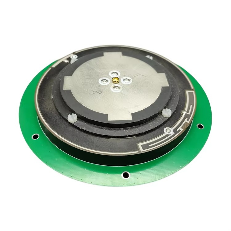
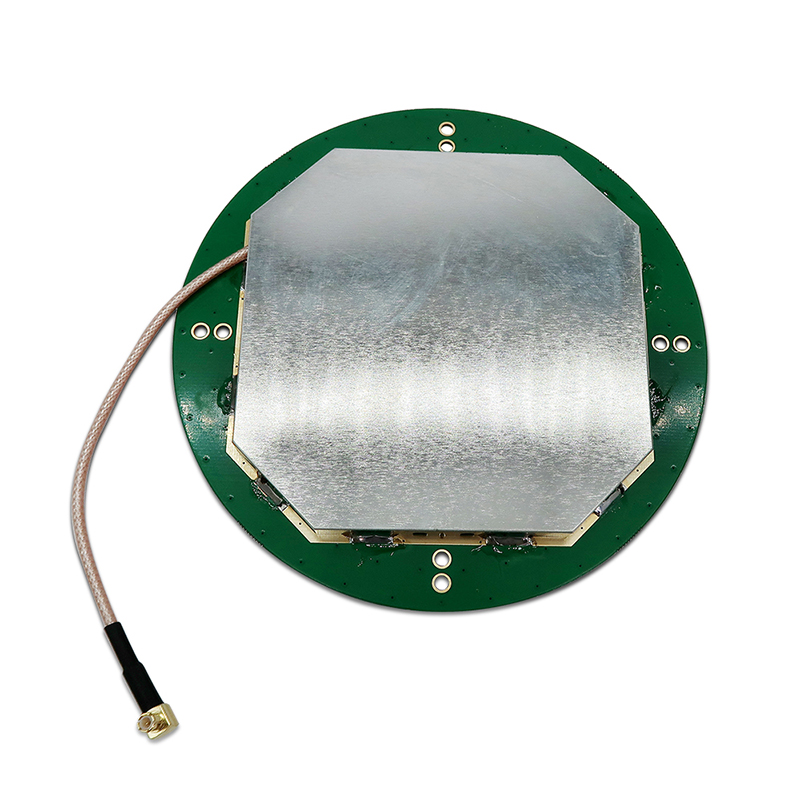
The size of D146.5*62.5mm (diameter 146.5mm, height 62.5mm) strikes a balance between performance and portability. This compact form factor allows for flexible installation in various settings, from surveying equipment mounted on tripods to the roofs of autonomous vehicles or drones. Despite its relatively small size, the antenna’s internal design—including specialized elements for each frequency band—ensures that it can capture and process signals from multiple constellations without mutual interference. The dimensions also make it suitable for integration into ruggedized enclosures, protecting it from environmental hazards in outdoor applications such as construction sites or remote field surveys.
A critical parameter for RTK performance is the axial ratio, specified at ≤3dB. Axial ratio measures the degree of circular polarization purity, with a lower value indicating more perfect circular polarization. GNSS satellites transmit signals using circular polarization (either right-hand or left-hand), which minimizes signal loss caused by atmospheric effects, reflections, and Faraday rotation. An axial ratio of ≤3dB ensures that the antenna maintains near-ideal circular polarization across its operating frequencies, maximizing signal absorption and reducing errors caused by polarization mismatch. This is particularly important for RTK applications, where even minor signal losses can translate into positioning errors of several centimeters—unacceptable for precision tasks like land surveying or infrastructure alignment.
The peak gain of ≥5dBi is optimized to amplify weak satellite signals without introducing excessive noise. Gain in RTK antennas is a delicate balance: sufficient amplification is needed to capture faint signals from low-elevation satellites (which traverse longer atmospheric paths), but too much gain can amplify noise, degrading signal quality. The ≥5dBi specification ensures that the antenna can effectively boost useful signals while maintaining a high signal-to-noise ratio (SNR), a key factor in achieving centimeter-level accuracy. This gain is distributed across the antenna’s frequency bands, with slight variations to account for differences in signal strength and atmospheric attenuation at each frequency. For example, the L2 and G2 bands (around 1227–1246 MHz) may require slightly higher gain than L1 due to higher atmospheric absorption, and the antenna’s design accommodates these variations.
The horizontal coverage angle of 360° is a defining feature for applications requiring omnidirectional satellite visibility. This means the antenna can receive signals from satellites located anywhere in the sky, from the horizon to the zenith, without directional bias. In contrast, some antennas have limited coverage angles, restricting their performance in environments where satellites are clustered in specific parts of the sky (e.g., polar regions). The 360° horizontal coverage ensures that the Multi-System RTK Antenna can track satellites across the entire celestial sphere, maximizing the number of visible satellites and improving positioning redundancy. This is crucial for RTK, which relies on measurements from multiple satellites to resolve ambiguities in carrier-phase data and achieve high precision.
Phase Center Error (PCE) of 2mm is perhaps the most critical specification for RTK accuracy. The phase center is the point within the antenna where the electrical signal is considered to originate, and any variation in this point (error) can directly translate into positioning errors. A PCE of 2mm means that the antenna’s phase center remains stable within 2 millimeters across all frequencies and signal directions, ensuring that measurements are consistent and reliable. This level of stability is achieved through meticulous design of the antenna’s radiating elements and feed network, minimizing variations caused by signal angle, frequency, or temperature. For surveyors and engineers, this translates to confidence that their measurements are accurate to within a few millimeters—essential for projects like road construction, where misalignments can lead to costly rework.
The operating temperature range of -40°C to +85°C underscores the antenna’s durability in extreme environments. This wide range ensures reliable performance in polar expeditions, desert surveys, or industrial settings where temperatures fluctuate dramatically. The antenna’s internal components—including its printed circuit boards (PCBs), connectors, and radiating elements—are designed to withstand thermal expansion and contraction, maintaining electrical stability even as temperatures swing. For example, in arctic conditions, the antenna’s materials resist brittleness, while in desert heat, they avoid thermal degradation that could alter the phase center or reduce gain. This durability makes the antenna suitable for year-round, all-weather operations in remote or harsh locations.
The mounting method—screw mounting— provides a secure and stable installation, critical for maintaining phase center stability and positioning accuracy. Screw mounting ensures that the antenna remains rigidly fixed to its base (e.g., a surveying tripod, vehicle roof, or drone frame), minimizing vibrations or movement that could introduce errors. Unlike adhesive mounts, which may degrade over time or in extreme temperatures, screw mounting offers long-term reliability, even in high-vibration environments like construction vehicles or off-road drones. The mounting hardware is typically made from corrosion-resistant materials like stainless steel, ensuring that it remains secure in wet or salty environments (e.g., marine surveys or coastal construction).
The MCX connector is a compact, high-performance interface that balances size and signal integrity. MCX connectors are smaller than standard SMA connectors, making them ideal for the antenna’s compact form factor while maintaining low signal loss. They feature a push-pull coupling mechanism that ensures quick, secure connections—important for field technicians who may need to set up or reconfigure equipment quickly. The MCX connector is also shielded to minimize electromagnetic interference (EMI) from nearby electronics, a critical consideration in RTK systems where even minor interference can corrupt delicate carrier-phase measurements. Compatibility with MCX cables (often RG174 or similar low-loss coaxial cables) ensures that signal loss between the antenna and the RTK receiver is minimized, preserving the integrity of the high-precision data.
In terms of operational principles, the Multi-System RTK Antenna works in tandem with an RTK receiver to achieve centimeter-level positioning. RTK technology relies on measuring the carrier phase of satellite signals, which oscillate at high frequencies (e.g., 1.5 GHz for L1). By comparing the carrier phase measurements from a rover antenna (the Multi-System RTK Antenna) with those from a fixed base station antenna (with a known position), the receiver can calculate the rover’s position with extraordinary precision. The antenna’s ability to receive signals from multiple constellations increases the number of carrier-phase measurements available, reducing the time required to resolve ambiguities (unknown integers in the phase difference) and improving accuracy in challenging conditions.
One of the key advantages of the Multi-System RTK Antenna is its resilience to signal obstructions. In urban canyons or dense forests, where buildings or trees block some satellite signals, the antenna’s support for multiple constellations ensures that enough signals remain to maintain RTK lock. For example, if GPS signals are blocked by a skyscraper, GLONASS or BeiDou signals from a different part of the sky may still be available, allowing the system to continue operating with high precision. This resilience is particularly valuable for autonomous vehicles, which require continuous, reliable positioning to navigate safely through complex environments.
Another significant benefit is its compatibility with evolving GNSS constellations. As satellite systems like Galileo and BeiDou expand their coverage and add new frequency bands, the antenna’s support for their current bands (e.g., Galileo E5b, BeiDou B3) ensures that it can leverage future enhancements. This future-proofing makes the antenna a long-term investment, reducing the need for costly upgrades as GNSS technology advances.
The Multi-System RTK Antenna finds applications across a wide range of industries, each leveraging its high precision and reliability. In land surveying and mapping, it enables surveyors to collect data with centimeter accuracy, essential for creating detailed topographic maps, defining property boundaries, or planning infrastructure projects. The antenna’s portability and 360° coverage make it suitable for use with backpack-mounted or drone-based surveying systems, allowing access to remote or difficult-to-reach areas.
In agriculture, the antenna is integrated into precision farming equipment, such as GPS-guided tractors and harvesters. By providing accurate positioning, it enables farmers to apply fertilizers, pesticides, and seeds with precise timing and placement, reducing waste and improving crop yields. In vineyards or orchards, where rows are closely spaced, the antenna’s high precision ensures that machinery avoids damaging plants, even at high speeds.
Construction and civil engineering rely on the antenna for tasks like grading, road alignment, and building foundation layout. The 2mm phase center error ensures that structures are built to exact specifications, minimizing errors that could compromise safety or functionality. For example, in bridge construction, the antenna’s precise positioning ensures that support columns are aligned correctly, preventing structural stress over time.
Marine and offshore applications also benefit from the antenna’s durability and precision. It is used in hydrographic surveying to map the seafloor with high accuracy, supporting navigation safety and offshore construction projects like oil rig placement. The antenna’s resistance to saltwater corrosion and extreme temperatures makes it suitable for long-term deployment on ships or buoys.
In autonomous systems—including self-driving cars, drones, and robots—the Multi-System RTK Antenna provides the high-precision positioning needed for safe, reliable operation. Autonomous vehicles use RTK data to navigate lanes, avoid obstacles, and maintain accurate trajectories, even in areas without reliable GPS coverage. Drones equipped with the antenna can perform tasks like 3D mapping, infrastructure inspection, or search-and-rescue missions with centimeter-level precision, ensuring that data is accurate and actionable.
Despite its many strengths, the Multi-System RTK Antenna has considerations for users. Its high precision requires a clear view of the sky, as signal blockages (e.g., deep canyons, dense forests) can reduce the number of visible satellites, potentially degrading accuracy. In such cases, auxiliary technologies like inertial measurement units (IMUs) may be used to complement RTK data, maintaining positioning during brief signal losses. Additionally, the antenna’s performance is dependent on the quality of the RTK receiver and base station network, making system integration a critical factor in achieving optimal results.
In conclusion, the Multi-System RTK Antenna represents the pinnacle of high-precision positioning technology, combining broad satellite system support, meticulous engineering, and rugged durability to deliver centimeter-level accuracy across diverse applications. Its ability to receive signals from GPS, GLONASS, BeiDou, and Galileo ensures reliability in any region, while specifications like 2mm phase center error and ≤3dB axial ratio guarantee the precision required for critical tasks. From surveying and agriculture to autonomous systems and construction, this antenna enables innovations that depend on accurate, real-time positioning. As GNSS technology continues to evolve, the Multi-System RTK Antenna will remain a cornerstone of high-precision applications, driving progress in industries where accuracy is not just a requirement but a necessity. Its blend of performance, versatility, and durability makes it an invaluable tool for professionals seeking to push the boundaries of what is possible in positioning and navigation.

 86 0755 2819 9597
Lucy Yang | lucy.y@toxutech.com
Nicole Li | nicole@toxutech.com
Dotty Zhao | sales04@toxutech.com
Global Business Director / Sales Team / Global Operations


 En
En Cn
Cn Korean
 Home >


