

-
Products -PCBA Manufacturing RF Connectors RF Cable Assemblys Embedded Antennas External Antennas Positioning Chips and Modules
RF Connectors

RF Cable Assemblys
Embedded Antennas
External Antennas
Positioning Chips and Modules


 Language


Language


The evolution of Global Navigation Satellite Systems (GNSS) from a tool for basic positioning to an enabling technology for autonomous driving and advanced robotics is one of the most significant technological narratives of the 21st century. At the heart of this transformation lies a critical, yet often overlooked, component: the antenna. Specifically, the Multi-Band Real-Time Kinematic (RTK) car antenna represents the pinnacle of GNSS receiver technology, acting as the precise sensory organ that allows a vehicle to understand its position on Earth with centimeter-level accuracy. This overview delves into the fundamental role of this technology, its place within the broader GNSS ecosystem, and why it is indispensable for the future of mobility.
To appreciate the multi-band RTK antenna, one must first understand the limitations of standard GNSS receivers found in everyday smartphones and basic car navigation systems. These consumer-grade devices typically use a single-frequency antenna (most commonly the L1 band, ~1575.42 MHz). They provide positional accuracy within 3 to 5 meters under good conditions—sufficient for guiding a human driver along a highway but utterly inadequate for a machine that must distinguish between a lane and a shoulder, or a curb and a pedestrian crossing. This meter-level error arises from various sources, including satellite clock and orbit errors, and most significantly, ionospheric delay. The ionosphere, a layer of charged particles in the upper atmosphere, slows down and bends GNSS signals, introducing a variable and substantial error that single-frequency receivers can only partially model and correct.
The quest for greater accuracy led to the development of Real-Time Kinematic (RTK) techniques. RTK is a method that uses carrier-phase measurements from GNSS signals, which are far more precise than the code-phase measurements used in standard positioning. However, to resolve the integer ambiguity inherent in carrier-phase measurements (i.e., determining the exact number of whole wavelengths between the satellite and receiver), RTK requires a reference station at a known, fixed location. This base station calculates the error for each satellite signal it receives and broadcasts these error corrections (via a radio link or cellular network) to a rover—the moving receiver, such as our car antenna. By applying these precise corrections in real-time, the rover can achieve phenomenal accuracy.
This is where the "multi-band" aspect becomes crucial. A multi-band antenna is designed to receive signals on two or more distinct frequency bands from each satellite constellation (GPS L1/L2/L5, Galileo E1/E5a/E5b/E6, GLONASS G1/G2/G3, BeiDou B1/B2/B3). The primary technical advantage of receiving multiple frequencies is the ability to directly measure and eliminate the ionospheric delay. Different frequencies are delayed by different amounts as they pass through the ionosphere. By comparing the phase of the signals on two frequencies (e.g., L1 and L2), the receiver can calculate the exact ionospheric delay and remove it almost entirely from the position solution. This process, known as ionospheric correction, is the single most important factor enabling robust centimeter-level accuracy.
Therefore, a multi-band RTK car antenna is not a simple passive component; it is a sophisticated, active electromagnetic system engineered for maximum precision and reliability. It is the front-end that captures weak signals from multiple satellite constellations across multiple frequencies, while simultaneously rejecting noise, multipath interference (signals reflected off buildings or the ground), and jamming attempts. Its design is a complex balance of electrical engineering, materials science, and aerospace principles, all packaged into a robust form factor capable of surviving the harsh environmental conditions of an automotive application.
The applications for this technology extend far beyond the obvious goal of self-driving cars. It is the enabling technology for precision agriculture (autonomous tractors), drone delivery systems, marine navigation, machine control in construction, and scientific surveying. In the automotive context, it is the foundational sensor for Advanced Driver-Assistance Systems (ADAS) like lane-keeping assistance, adaptive cruise control, and automated parking, providing the absolute positioning context that complements relative sensors like cameras, LiDAR, and radar.
In summary, the multi-band RTK car antenna is the critical gateway between the satellite constellations orbiting 20,000 km above and the decision-making algorithms of an autonomous vehicle. It transforms the noisy, error-prone signals from space into a pristine, ultra-precise data stream that tells the vehicle exactly where it is, which way it is pointing, and how fast it is moving. Without this high-fidelity input, the promise of safe and efficient autonomy remains out of reach. It is the unsung hero of the precision positioning revolution, a masterpiece of modern engineering that turns the abstract concept of centimeter-accurate global navigation into a practical reality.
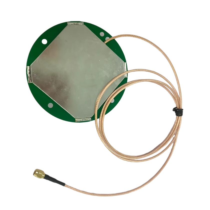
The design and construction of a multi-band RTK car antenna is a meticulous exercise in electromagnetic optimization, material selection, and environmental hardening. Unlike a simple GPS patch antenna, it is a complex system where every element—from the shape of the radiating element to the composition of the plastic radome—is critically important to achieving the required performance. This section deconstructs the anatomy of a high-performance automotive RTK antenna, exploring the key components and the engineering challenges involved in their integration.
1. The Radiating Element: The Heart of the Antenna
The core function of the antenna is to convert electromagnetic waves from satellites into electrical signals for the receiver. This is done by the radiating element. For multi-band operation, a common and highly effective design is the stacked-patch antenna.
Structure: This consists of multiple concentric or rectangular patches of conductive material (often copper), printed on dielectric substrates and stacked vertically. The top, smaller patch is typically tuned to the highest frequency band (e.g., GPS L1, Galileo E1), while the larger, lower patch is tuned to a lower frequency band (e.g., GPS L2/L5, Galileo E5).
Principle: Each patch resonates at its designed frequency, allowing a single physical unit to efficiently capture energy from multiple bands. The coupling between the patches is carefully modeled and optimized to ensure good performance across all bands without interference.
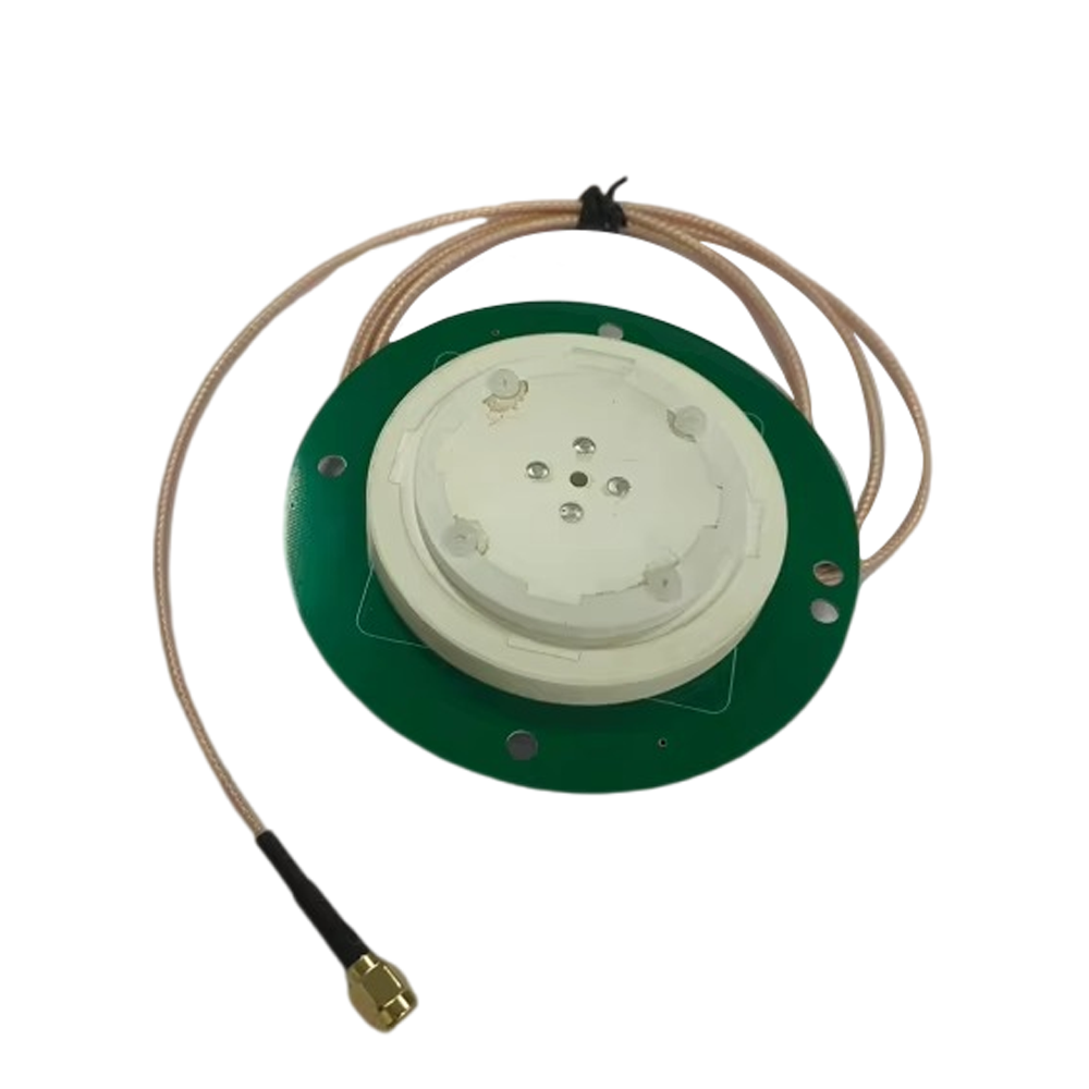
2. The Ground Plane: The Foundation of Performance
The radiating element must be mounted over a conductive ground plane. The size and quality of this ground plane are paramount. It serves several key functions:
Directionality: It shapes the antenna's radiation pattern, directing energy upward towards the sky (hemispherical pattern) and rejecting signals coming from below the horizon, which are typically noise or multipath reflections from the ground or the car's body.
Shielding: It acts as an electromagnetic shield, blocking noise generated by the vehicle's electronics from interfering with the weak GNSS signals.
Performance: A larger ground plane generally improves the antenna's gain and phase center stability—a critical factor for RTK. The phase center is the virtual point from which the radiation seems to emanate; for RTK, this point must be stable and consistent across all frequencies and angles to avoid introducing measurement errors. High-end antennas characterize and document the phase center variations (PCV) so the receiver can correct for them.
3. The Low-Noise Amplifier (LNA): Boosting the Signal
GNSS signals are incredibly weak by the time they travel over 20,000 km to reach the Earth's surface, often compared to the light from a bright star viewed from the ground. They are easily drowned out by cable loss and receiver noise.
Function: An LNA is placed immediately after the radiating element (often within the same housing) to amplify the signals before any significant loss occurs. This is an "active" antenna.
Key Specifications: The LNA must have very low internal noise (a low Noise Figure), high gain to boost the signal, and a linear response across all target frequency bands to avoid distorting the signals. It must also be resilient against out-of-band interference (e.g., from cellular or radar signals) to prevent saturation.
4. The Filtering System: Isolating the Signal
The electromagnetic spectrum is crowded with energy from other services (e.g., 4G/5G, WiFi, Bluetooth). Filters are essential to reject this interference.
Band-Pass Filters: These are integrated into the RF chain, typically after the LNA, to allow only the specific GNSS frequencies (e.g., 1150-1300 MHz for L5/E5, 1550-1610 MHz for L1/E1) to pass through to the output.
Surge Protection: Given the antenna is mounted externally on a vehicle, it must include protection against electrostatic discharge (ESD) and voltage surges from events like lightning strikes nearby.
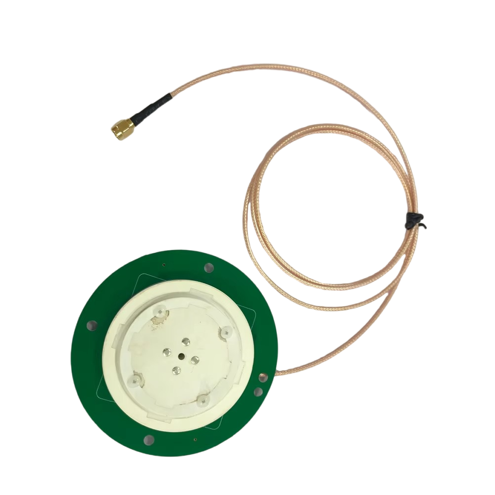
5. The Radome: The Protective Shell
The entire internal assembly is protected by a outer shell or radome.
Material: It is made from a material that is radio-frequency transparent—meaning it has minimal effect on the signal passing through it. Common materials include high-grade plastics like polycarbonate or ABS.
Design: The shape, thickness, and dielectric constant of the radome are all part of the electromagnetic design. A poorly designed radome can detune the antenna, reflect signals, or create its own multipath. The radome must also be mechanically robust, UV resistant to prevent yellowing and degradation from sun exposure, and waterproof (typically rated IP67 or higher).
6. The Choke Ring (Optional but Common): The Multipath Killer
Many high-precision antennas incorporate a ground plane designed as a choke ring.
Structure: A choke ring is a series of concentric, corrugated grooves surrounding the radiating element.
Function: It acts as an electromagnetic choke, creating a high impedance path for signals arriving at low elevation angles (i.e., signals reflected from the ground or the car's roof). These reflected signals (multipath) are a primary source of error in precision GNSS. The choke ring effectively suppresses them, ensuring the antenna primarily "sees" only the direct line-of-sight signals from satellites above.
7. Calibration and Phase Center Characterization
A final, crucial step in the manufacturing of a survey-grade multi-band RTK antenna is precise calibration. Using an anechoic chamber or a precise robotic arm on a calibrated baseline, manufacturers measure the antenna's exact performance parameters:
Phase Center Offset (PCO): The vector difference between the antenna's physical reference point and its electrical phase center.
Phase Center Variation (PCV): How the phase center moves as a function of the satellite's elevation and azimuth angle.
This data is published in a calibration file (often in ANTEX format). High-end RTK receivers use this file to correct the raw measurements, ensuring that the antenna itself does not become a source of error, a process vital for achieving centimeter-level ambiguity resolution.
In conclusion, the construction of a multi-band RTK antenna is a fusion of advanced RF engineering, precision manufacturing, and rigorous testing. It is far more than a simple piece of metal; it is a system engineered to perform with exceptional accuracy and reliability under the demanding conditions of the automotive environment, making it the trusted starting point for any high-integrity navigation solution.
The operation of a multi-band RTK system, with the antenna as its front-end, is a complex dance of physics, mathematics, and data processing. Understanding its working principles requires moving beyond the antenna itself to see its role within the entire RTK engine. The antenna's job is to provide the cleanest possible raw data; the receiver's job is to process this data into a precise position. This section explains the step-by-step process, from signal reception to centimeter-accurate fix.
Step 1: Multi-Constellation, Multi-Frequency Signal Acquisition
The multi-band antenna simultaneously receives signals from all visible satellites across all available constellations (GPS, Galileo, GLONASS, BeiDou) and frequencies (L1, L2, L5, E1, E5a, E5b, etc.). The primary observables it provides to the receiver are:
C/A Code (Coarse/Acquisition Code): Used for initial satellite acquisition and providing a standard, meter-level position fix.
Carrier Phase: The precise measurement of the phase of the underlying L-band carrier wave. This is the key to RTK. While the C/A code wavelength is about 300 meters long, the L1 carrier wavelength is only 19 cm. Measuring the phase of this wave to within 1% of a cycle provides millimeter-level precision—but with an unknown integer number of whole wavelengths, known as the integer ambiguity.
Step 2: Data Streaming and Initial Processing
The amplified and filtered signals from the antenna are sent via a coaxial cable to the RTK receiver module. The receiver's first task is to track the codes and carrier phases of dozens of satellites simultaneously. It generates pseudorange measurements (based on the code) and accumulated carrier phase measurements (in cycles) for each satellite signal.
Step 3: The Role of the Base Station
A nearby base station (typically within 10-40 km), positioned on a known surveyed point, performs the exact same measurements. Because its location is known exactly, it can calculate the exact error in each satellite's signal. It computes the difference between the measured pseudorange and the true geometric range for each satellite. These error corrections are packaged into a standardized format (e.g., RTCM3) and transmitted to the rover (the car) via a radio link or cellular modem.
Step 4: RTK Engine: Ambiguity Resolution - The Core Challenge
The rover receiver receives the correction data from the base station. The magic happens in the RTK engine, which employs a sophisticated Kalman filter or least-squares estimator. The process involves:
Applying Corrections: The rover uses the base station's corrections to virtually eliminate common errors: satellite clock and orbit errors, and ionospheric and tropospheric delays. This is where multi-band shines: by using dual or triple frequencies, the ionospheric delay can be calculated directly and removed with incredible efficiency, making the correction process much faster and more reliable, especially over longer baselines.
Double Differencing: The receiver creates "double differences" by subtracting measurements between two satellites and between the rover and base station. This mathematical operation cancels out almost all remaining common errors.
Integer Ambiguity Resolution: The double-differenced carrier phase measurement is extremely precise but still contains the unknown integer ambiguity. Resolving this integer is the single most critical task in RTK. The engine uses sophisticated search algorithms (e.g., LAMBDA method) to find the set of integers that best fits the data from all satellites and all frequencies. The use of multiple frequencies is a huge advantage here, as different frequencies have different wavelengths, creating a "virtual" wavelength that makes the integer search faster and more robust.
Step 5: The Fixed Solution
Once the integer ambiguities are correctly resolved, the system enters the RTK Fixed state. The carrier phase measurements are now effectively exact ranges to the satellites, yielding a position solution with 2-4 cm horizontal accuracy in real-time. The receiver also calculates precise velocity and heading from the rate of change of the carrier phase (Doppler shift).
Step 6: Maintaining the Fix and Handling Challenges
The RTK engine's work is not done. It must continuously:
Monitor Cycle Slips: Temporary signal blockages (e.g., driving under a bridge or tree canopy) can cause the receiver to lose count of the carrier cycles (a cycle slip). The engine must detect these slips and quickly re-resolve the ambiguity for that satellite.
Reject Multipath: While the antenna's design (e.g., choke ring) suppresses multipath, the receiver's algorithms also play a role in identifying and weighting out corrupted measurements.
Manage Base Station Rover Geometry: The position accuracy depends on the geometric spread of satellites. The engine calculates a dilution of precision (DOP) value; a lower DOP (better satellite geometry) means higher confidence in the solution.
In essence, the multi-band antenna provides the high-quality, multi-frequency raw ingredients. The RTK engine is the master chef that combines these ingredients with a recipe of corrections and complex algorithms to produce the final exquisite dish: a centimeter-accurate position. The entire process is a testament to modern engineering, turning the faint whispers of satellites into a robust and reliable navigation capability for machines on the move.
The adoption of multi-band RTK technology offers transformative advantages for automotive positioning, but it is not without its significant challenges and cost implications. A clear understanding of both sides is essential for evaluating its suitability for any given application.
Advantages:
Unparalleled Accuracy: The foremost advantage is centimeter-level positioning in real-time. This is the foundational requirement for any application where a machine, rather than a human, is making safety-critical navigation decisions, such as distinguishing between a driving lane and a bike lane.
Exceptional Reliability and Convergence Time: Multi-band receivers resolve the integer ambiguities (achieve a fixed solution) much faster than single-band RTK systems. This is known as rapid convergence. They also maintain this fixed solution more reliably in challenging environments because the multiple frequencies allow for robust internal validation of the solution and superior handling of ionospheric disturbances.
Robustness in Difficult Environments: The multi-frequency capability provides inherent resistance to ionospheric errors, which can be significant during periods of high solar activity or at equatorial latitudes. Furthermore, the ability to track more signals from more constellations means the system has more data to work with, improving availability and accuracy in urban canyons or partial obscuration scenarios where the sky view is limited.
High Resistance to Multipath: The advanced design of the antenna (e.g., choke rings, carefully engineered ground planes) actively suppresses multipath signals. The receiver can also use signal-to-noise ratio (SNR) data and multi-frequency comparisons to further identify and mitigate the effects of any remaining multipath.
Absolute Positioning: Unlike cameras, LiDAR, and radar, which provide relative positioning (i.e., where an object is relative to the vehicle), GNSS provides absolute positioning in a global frame (i.e., the vehicle's exact latitude, longitude, and altitude). This is critical for map matching, route planning, and vehicle-to-everything (V2X) communication where a common global reference is needed.
Challenges:
Cost: This is the most significant barrier to mass adoption. Multi-band antennas are complex RF assemblies with expensive materials and require precise calibration. The receivers need powerful processors to handle the computational load of processing dozens of signals and running complex RTK algorithms. The total system cost, including the antenna, receiver, and a subscription for cellular correction services, can be orders of magnitude higher than a standard GPS module.
Dependence on Correction Data: RTK is not a standalone technology. It requires a continuous, low-latency data link to a base station or a network of base stations (e.g., NTRIP via cellular). If this communication link is lost or interrupted, the system will revert to a lower-accuracy mode (float or standalone GNSS), which may not be sufficient for autonomous functions. This creates a dependency on cellular coverage and reliability.
Baseline Length Limitations: While multi-band significantly extends the useful range between the rover and base station (up to 50-80 km under good conditions), performance still degrades with distance. The errors corrected by the base station (especially tropospheric delay) become less correlated the farther apart the two units are, making ambiguity resolution more difficult. For continent-scale deployment, this requires a dense network of base stations (CORS networks).
Signal Vulnerability: GNSS signals are inherently weak and susceptible to both intentional jamming (using cheap, portable jammers) and unintentional interference from other electronic systems. While the antenna and receiver can include mitigation techniques, a powerful enough jammer can render the system useless. This is a critical safety and security concern.
Integration Complexity: Integrating a high-precision GNSS system is more complex than simply mounting an antenna. The placement of the antenna on the vehicle is critical—it must have a clear, unobstructed view of the sky and be away from other emitting antennas. The phase center characteristics must be accounted for in the vehicle's coordinate model. The system must be tightly coupled with the vehicle's inertial measurement unit (IMU) to provide smooth, continuous positioning during brief GNSS outages.
In conclusion, the advantages of multi-band RTK are profound, offering a level of accuracy that is enabling new technological paradigms. However, the challenges of cost, dependency, and vulnerability mean it is rarely used alone. It is most powerful when fused with other sensors like IMUs, cameras, and LiDAR in a sensor fusion framework, creating a resilient and reliable positioning system where the strengths of one technology compensate for the weaknesses of another.
The deployment of multi-band RTK technology is already transforming numerous industries, with its automotive applications sitting at the forefront of a mobility revolution. Its journey from a specialized surveying tool to a potential automotive-grade sensor outlines a clear path for future innovation.
Current Applications:
Autonomous Vehicle Development and Testing: Every developer of self-driving cars (e.g., Waymo, Cruise, Argo AI) uses multi-band RTK systems as the "ground truth" reference for testing and validating their proprietary sensor suites (LiDAR, radar, cameras). The precise pose (position and attitude) data is used to map environments and evaluate the performance of the autonomous driving algorithms.
Advanced Driver-Assistance Systems (ADAS): While current production ADAS mostly rely on other sensors, high-precision GNSS is beginning to play a role in "ADAS with foresight." For example, it can alert the system to an upcoming sharp curve or highway junction, allowing for smoother and earlier braking or acceleration than camera-vision alone could provide.
Precision Agriculture: Autonomous tractors and harvesters use multi-band RTK to navigate fields with centimeter accuracy, enabling practices like automated steering, variable rate application of seeds and fertilizer, and yield mapping. This maximizes efficiency and reduces waste and environmental impact.
Drones and Unmanned Aerial Vehicles (UAVs): RTK is critical for drone applications requiring precise positioning, such as aerial surveying, mapping, infrastructure inspection, and precision payload delivery. It enables stable hovering in windy conditions and accurate landing on a target.
Smart Infrastructure and V2X: For Vehicle-to-Everything communication to work, especially for safety-critical messages like hazard warnings, the vehicle's reported location must be highly accurate. Multi-band RTK provides the necessary integrity for these systems.
Robotics: Mobile robots in logistics, warehouses, and ports use RTK for precise navigation in large, semi-structured outdoor environments.
Future Trends:
Mass Market Automotive Integration: The most significant trend is the push to reduce the cost, size, and power consumption of multi-band RTK systems to make them viable for integration into consumer vehicles. This will not be for full autonomy initially, but for enhanced ADAS features, improved emergency response (e.g., more accurate crash location), and insurance telematics.
Tight Coupling with Inertial Navigation Systems (INS): The fusion of RTK with high-performance IMUs is becoming deeper and more sophisticated. Tightly-coupled systems use the RTK and IMU data at the raw measurement level, allowing the IMU to "hold" the position during GNSS outages of several seconds or even minutes, and to aid the RTK engine in rejecting multipath and maintaining a fixed solution. This is essential for urban driving.
Leveraging Constellation Modernization: New signals like GPS L5 and Galileo E5 are designed for safety-of-life applications with higher power and advanced modulation. Future antennas and receivers will be optimized for these modern signals, offering improved robustness and accuracy right out of the gate.
Cyber Resilience: As vehicles become more connected, the threat of jamming and spoofing (broadcasting fake GNSS signals) grows. Future systems will incorporate advanced anti-jam and anti-spoofing technologies, such as controlled reception pattern antennas (CRPAs) that can nullify interference sources, and cryptographic authentication of signals from satellites.
Cellular and Satellite-Based Augmentation Integration: The line between GNSS and other positioning technologies will blur. Future automotive antennas may be "multi-everything"—integrating GNSS, cellular modem antennas (for 5G positioning), and even Low Earth Orbit (LEO) satellite communication antennas into a single package, creating a resilient and ubiquitous positioning capability.
Standardization and Safety-Certification: For use in production vehicles, these systems will need to be certified to automotive safety standards like ISO 26262 (ASIL-B or higher). This requires robust design, redundancy, and continuous self-monitoring to ensure the system can detect faults and inform the vehicle if the GNSS solution is no longer trustworthy.
The future of the multi-band RTK car antenna is not just as a standalone sensor, but as the core of a hybridized, resilient, and certifiable Positioning, Navigation, and Timing (PNT) unit. It will be an essential piece of the puzzle, working in concert with other technologies to provide the uninterrupted and trustworthy location data that the autonomous driving stack demands to safely navigate our world.
Conclusion
The multi-band RTK car antenna is a masterpiece of modern engineering that embodies the convergence of radio frequency design, advanced materials science, and sophisticated software algorithms. It is far more than a simple accessory; it is the critical gateway that bridges the vast expanse of space, where GNSS satellites tirelessly orbit, and the immediate, safety-critical world of automotive navigation. By capturing faint, multi-frequency signals from multiple constellations and preparing them for processing, it provides the fundamental raw material from which centimeter-accurate positioning is forged.
As we have explored, its advantages are transformative. The unparalleled accuracy, robustness against error sources like the ionosphere and multipath, and the ability to provide absolute positioning in a global frame make it an enabling technology for autonomous driving, precision agriculture, and a host of other automated applications that are reshaping our economy and society. It delivers the precise "where" that allows machines to understand and interact with their environment on a human scale.
However, this capability does not come without its challenges. The technology remains costly and complex, creating a barrier for mass-market adoption. It introduces dependencies on external correction data and communication links, and its fundamental vulnerability to jamming and spoofing presents a non-trivial security concern. These limitations make it clear that multi-band RTK is not a silver bullet. It cannot and should not operate in isolation.
The path forward, therefore, lies not in relying solely on this one technology, but in its intelligent integration into a broader sensor fusion ecosystem. The future of automotive positioning is a synergistic combination where the absolute accuracy of multi-band RTK is seamlessly fused with the relative precision and high update rates of inertial measurement units (IMUs), the rich perceptual data from cameras and LiDAR, and the emerging complementary data from 5G cellular networks. In this framework, the strengths of each sensor compensate for the weaknesses of the others. The RTK system provides the stable global anchor that prevents the drift inherent in IMUs, while the IMU and vision systems provide continuous positioning when GNSS signals are temporarily blocked, and help the RTK engine distinguish between direct and reflected signals.
The ongoing trends of cost reduction, miniaturization, and integration with other communication technologies promise to gradually move multi-band RTK from the realm of development vehicles and high-end applications into consumer-grade automobiles. This will unlock new levels of ADAS performance and safety features long before full autonomy becomes a reality.
In conclusion, the multi-band RTK antenna is a foundational pillar of the autonomous revolution. It transforms the theoretical promise of global centimeter-scale navigation into a practical, reliable tool. While challenges remain, its continuous evolution and integration into redundant, multi-modal systems ensure that it will remain an indispensable component, providing the trusted ground truth upon which the future of automated mobility will be built. It is a testament to human ingenuity, a key that is unlocking a new era of machine perception and action.

 86 0755 2819 9597
Lucy Yang | lucy.y@toxutech.com
Nicole Li | nicole@toxutech.com
Dotty Zhao | sales04@toxutech.com
Global Business Director / Sales Team / Global Operations


 En
En Cn
Cn Korean
 Home >


