

-
Products -PCBA Manufacturing RF Connectors RF Cable Assemblys Embedded Antennas External Antennas Positioning Chips and Modules
RF Connectors

RF Cable Assemblys
Embedded Antennas
External Antennas
Positioning Chips and Modules


 Language


Language


GNSS encompasses a constellation of satellites orbiting the Earth, including the well - known Global Positioning System (GPS) from the United States, GLONASS from Russia, Galileo from the European Union, and BeiDou from China, among others. These satellite systems transmit signals that can be received by antennas on Earth, allowing receivers to calculate their position, velocity, and time with remarkable accuracy.
Multi - band GNSS marine antennas are designed to receive signals from multiple frequency bands simultaneously. Different GNSS constellations operate on various frequency bands, and by being able to capture signals from multiple bands, these antennas offer several advantages. Firstly, they can improve the accuracy of positioning. Signals from different bands may experience different levels of interference and propagation delays. By combining the information from multiple bands, the receiver can more effectively mitigate these errors and achieve a more precise location fix. For example, the L1, L2, and L5 bands in GPS have different characteristics. The L1 band is the most commonly used for general navigation, but the L2 and L5 bands can provide additional information for more accurate positioning, especially in challenging environments such as near - shore areas with significant multipath interference.
Secondly, multi - band antennas enhance the reliability of the GNSS signal reception. In the marine environment, signals can be blocked or weakened by various factors such as large waves, nearby land masses, or the superstructure of the vessel itself. By being able to switch between different frequency bands, the antenna has a better chance of maintaining a connection with the satellites and providing continuous positioning information. For instance, if the L1 band signal is severely attenuated due to a large wave, the antenna can rely on signals from other bands to keep the navigation system operational.
Moreover, multi - band GNSS marine antennas are essential for supporting the growing number of advanced marine applications. These include precision navigation for autonomous vessels, which require extremely accurate positioning to operate safely and efficiently. In addition, they are crucial for high - resolution mapping of the ocean floor, where precise location data is needed to create detailed bathymetric maps. They also play a significant role in real - time tracking of marine assets, such as fishing fleets or oil and gas platforms, enabling better management and monitoring.
The demand for multi - band GNSS marine antennas has been steadily increasing in recent years. This growth is driven by several factors. The expansion of global trade has led to a greater number of commercial vessels operating on the seas, all of which require reliable navigation systems. Additionally, the development of new marine industries, such as offshore wind energy and aquaculture, has created a need for accurate positioning for activities like installation and maintenance of wind turbines and monitoring of fish farms. Furthermore, regulatory requirements in many countries are becoming more stringent, mandating the use of highly accurate navigation systems for safety and environmental protection reasons. As a result, the market for multi - band GNSS marine antennas is expected to continue to grow in the coming years.
2.1 Antenna Elements
The design of multi - band GNSS marine antennas starts with the selection and configuration of antenna elements. One of the most common types of antenna elements used in these antennas is the patch antenna. Patch antennas are popular due to their compact size, low profile, and relatively simple construction. They consist of a flat conductive patch printed on a dielectric substrate, with a ground plane on the opposite side.
For multi - band operation, stacked patch antennas are often employed. In a stacked patch configuration, multiple patch elements are placed one above the other, with each patch tuned to a different frequency band. For example, a dual - band antenna might have one patch tuned to the L1 frequency band (around 1575.42 MHz for GPS) and another patch tuned to the L2 frequency band (around 1227.60 MHz for GPS). The stacked patches are designed to be electrically isolated from each other while still being able to receive signals from their respective frequency bands. This allows the antenna to capture and combine signals from multiple bands simultaneously.
Another type of antenna element used in multi - band GNSS marine antennas is the dipole antenna. Crossed dipole antennas, in particular, are useful for achieving circular polarization, which is important for GNSS applications. Circular polarization helps to reduce the effects of multipath interference, where the signal bounces off surfaces and arrives at the antenna at different times and angles. In a crossed dipole configuration, two dipole antennas are placed perpendicular to each other and fed with a 90 - degree phase difference. This creates a circularly polarized electromagnetic field that can more effectively receive signals from satellites regardless of their orientation relative to the antenna.
To achieve multi - band operation with dipole antennas, the dipole arms can be designed with multiple segments of different lengths. Each segment is resonant at a different frequency, allowing the antenna to operate on multiple bands. For example, an antenna might have dipole arms with four segments, each segment tuned to a different GNSS frequency band such as L1, L2, L5, and an additional band for a specific regional GNSS system.
2.2 RF Front - End Design
The RF front - end of a multi - band GNSS marine antenna is responsible for receiving, amplifying, and filtering the weak satellite signals. It is a critical part of the antenna system as it determines the antenna's sensitivity and its ability to reject interference.
The first stage in the RF front - end is the low - noise amplifier (LNA). The LNA is designed to amplify the extremely weak GNSS signals received by the antenna elements without adding too much noise. In the marine environment, the signals received from the satellites can be very weak, often on the order of nanovolts. The LNA needs to have a high gain (typically in the range of 20 - 40 dB) to boost these signals to a level that can be further processed by the subsequent stages. At the same time, it must have a low noise figure (ideally less than 1 dB) to ensure that the signal - to - noise ratio is not significantly degraded during the amplification process.
After amplification, the signals are passed through a series of filters. Band - pass filters are used to select the specific frequency bands of interest. Since multi - band antennas are designed to receive signals from multiple GNSS constellations and frequency bands, the band - pass filters need to be carefully designed to have a narrow passband around each desired frequency while rejecting signals outside of these bands. For example, a filter for the GPS L1 band would have a passband centered around 1575.42 MHz with a bandwidth of a few megahertz, while effectively blocking signals from other frequency bands such as cellular frequencies or satellite communication frequencies that could interfere with the GNSS signal.
In addition to band - pass filters, notch filters are also often used in the RF front - end. Notch filters are designed to reject specific frequencies that are known to cause interference. In the marine environment, there are various sources of interference, such as signals from nearby vessels' communication systems, radar systems, or even terrestrial broadcast stations. Notch filters can be tuned to reject these interfering frequencies, ensuring that only the desired GNSS signals are passed through to the next stage of the receiver.
2.3 Enclosure and Mounting
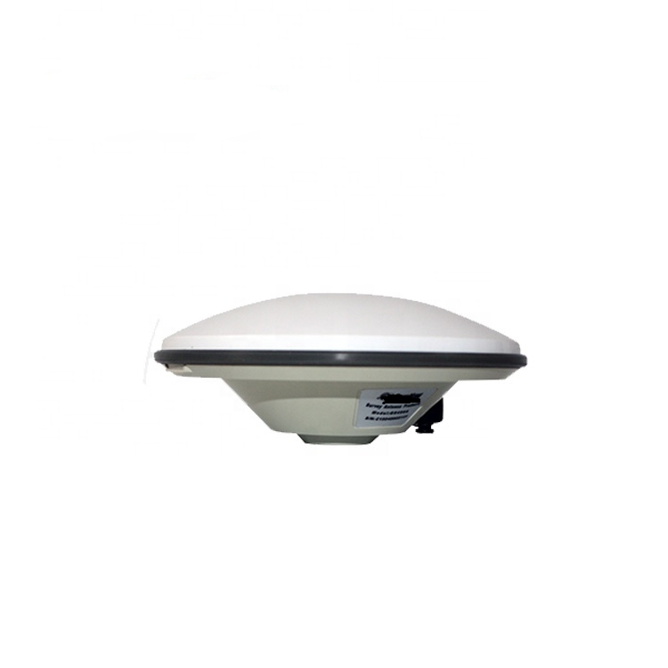
The enclosure of a multi - band GNSS marine antenna is designed to protect the internal components from the harsh marine environment. The enclosure must be waterproof, dustproof, and resistant to corrosion. Most marine - grade antennas are designed to meet the IP67 or higher ingress protection standards. IP67 means that the enclosure is completely dust - tight and can be submerged in water up to 1 meter deep for 30 minutes without water ingress.
The enclosure material is typically a weather - resistant polymer or a corrosion - resistant metal. Polymer enclosures, such as those made from acrylonitrile - butadiene - styrene (ABS) or polycarbonate, are lightweight, easy to mold into the desired shape, and offer good resistance to UV radiation, which is important as the antenna is often exposed to direct sunlight. Metal enclosures, on the other hand, can provide better shielding against electromagnetic interference, but they may be heavier and more expensive.
The shape of the enclosure is also carefully designed. Many marine antennas have a domed or hemispherical shape. This shape helps to prevent water from pooling on the antenna surface, reducing the risk of water ingress. It also has the advantage of providing a 360 - degree field of view for signal reception, which is important for maintaining a connection with satellites in different parts of the sky.
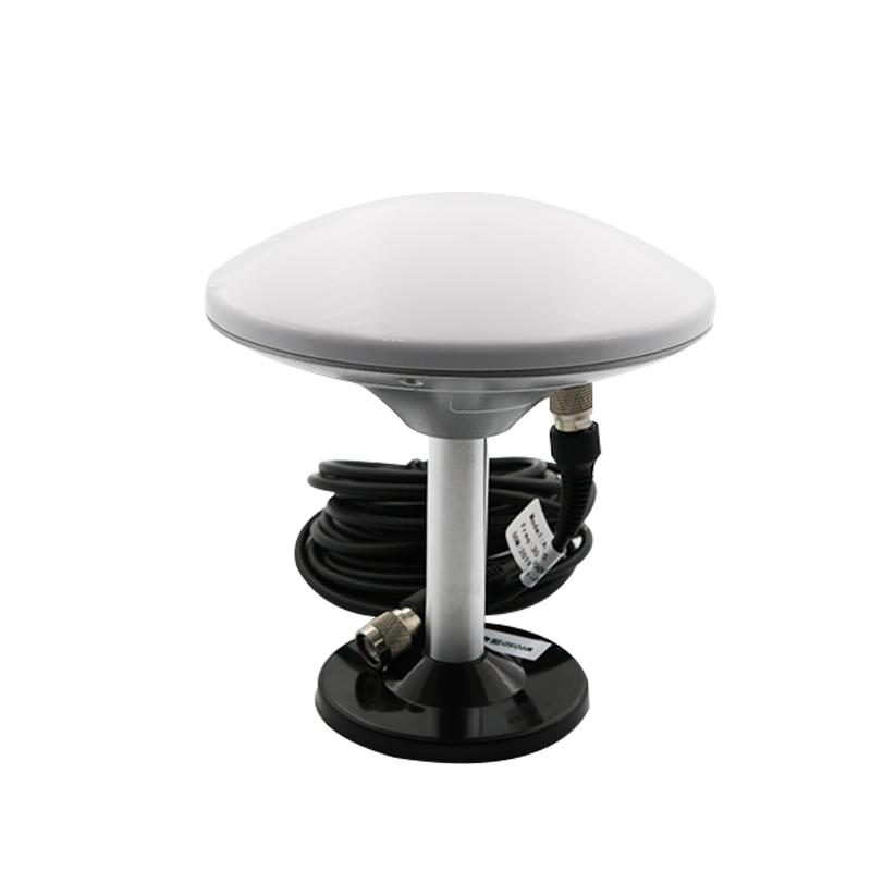
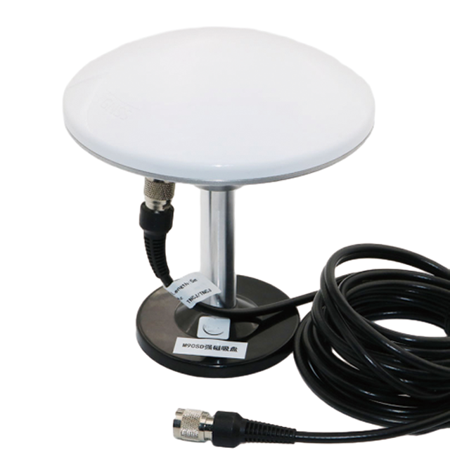
Mounting of the multi - band GNSS marine antenna is another crucial aspect of its design. The antenna needs to be mounted in a location that provides a clear view of the sky to ensure optimal signal reception. On most vessels, the antenna is mounted on the highest point of the superstructure, such as the mast or the radar arch. There are different types of mounting options available, including pole - mounting and deck - mounting. Pole - mounting involves attaching the antenna to a vertical pole, which can be adjusted in height to get the best possible view of the sky. Deck - mounting, on the other hand, involves attaching the antenna directly to the deck of the vessel. In both cases, the mounting hardware is designed to be strong and secure, able to withstand the vibrations and movements of the vessel in rough seas.
2.1 Antenna Elements
The design of multi - band GNSS marine antennas starts with the selection and configuration of antenna elements. One of the most common types of antenna elements used in these antennas is the patch antenna. Patch antennas are popular due to their compact size, low profile, and relatively simple construction. They consist of a flat conductive patch printed on a dielectric substrate, with a ground plane on the opposite side.
For multi - band operation, stacked patch antennas are often employed. In a stacked patch configuration, multiple patch elements are placed one above the other, with each patch tuned to a different frequency band. For example, a dual - band antenna might have one patch tuned to the L1 frequency band (around 1575.42 MHz for GPS) and another patch tuned to the L2 frequency band (around 1227.60 MHz for GPS). The stacked patches are designed to be electrically isolated from each other while still being able to receive signals from their respective frequency bands. This allows the antenna to capture and combine signals from multiple bands simultaneously.
Another type of antenna element used in multi - band GNSS marine antennas is the dipole antenna. Crossed dipole antennas, in particular, are useful for achieving circular polarization, which is important for GNSS applications. Circular polarization helps to reduce the effects of multipath interference, where the signal bounces off surfaces and arrives at the antenna at different times and angles. In a crossed dipole configuration, two dipole antennas are placed perpendicular to each other and fed with a 90 - degree phase difference. This creates a circularly polarized electromagnetic field that can more effectively receive signals from satellites regardless of their orientation relative to the antenna.
To achieve multi - band operation with dipole antennas, the dipole arms can be designed with multiple segments of different lengths. Each segment is resonant at a different frequency, allowing the antenna to operate on multiple bands. For example, an antenna might have dipole arms with four segments, each segment tuned to a different GNSS frequency band such as L1, L2, L5, and an additional band for a specific regional GNSS system.
2.2 RF Front - End Design
The RF front - end of a multi - band GNSS marine antenna is responsible for receiving, amplifying, and filtering the weak satellite signals. It is a critical part of the antenna system as it determines the antenna's sensitivity and its ability to reject interference.
The first stage in the RF front - end is the low - noise amplifier (LNA). The LNA is designed to amplify the extremely weak GNSS signals received by the antenna elements without adding too much noise. In the marine environment, the signals received from the satellites can be very weak, often on the order of nanovolts. The LNA needs to have a high gain (typically in the range of 20 - 40 dB) to boost these signals to a level that can be further processed by the subsequent stages. At the same time, it must have a low noise figure (ideally less than 1 dB) to ensure that the signal - to - noise ratio is not significantly degraded during the amplification process.
After amplification, the signals are passed through a series of filters. Band - pass filters are used to select the specific frequency bands of interest. Since multi - band antennas are designed to receive signals from multiple GNSS constellations and frequency bands, the band - pass filters need to be carefully designed to have a narrow passband around each desired frequency while rejecting signals outside of these bands. For example, a filter for the GPS L1 band would have a passband centered around 1575.42 MHz with a bandwidth of a few megahertz, while effectively blocking signals from other frequency bands such as cellular frequencies or satellite communication frequencies that could interfere with the GNSS signal.
In addition to band - pass filters, notch filters are also often used in the RF front - end. Notch filters are designed to reject specific frequencies that are known to cause interference. In the marine environment, there are various sources of interference, such as signals from nearby vessels' communication systems, radar systems, or even terrestrial broadcast stations. Notch filters can be tuned to reject these interfering frequencies, ensuring that only the desired GNSS signals are passed through to the next stage of the receiver.
2.3 Enclosure and Mounting
The enclosure of a multi - band GNSS marine antenna is designed to protect the internal components from the harsh marine environment. The enclosure must be waterproof, dustproof, and resistant to corrosion. Most marine - grade antennas are designed to meet the IP67 or higher ingress protection standards. IP67 means that the enclosure is completely dust - tight and can be submerged in water up to 1 meter deep for 30 minutes without water ingress.
The enclosure material is typically a weather - resistant polymer or a corrosion - resistant metal. Polymer enclosures, such as those made from acrylonitrile - butadiene - styrene (ABS) or polycarbonate, are lightweight, easy to mold into the desired shape, and offer good resistance to UV radiation, which is important as the antenna is often exposed to direct sunlight. Metal enclosures, on the other hand, can provide better shielding against electromagnetic interference, but they may be heavier and more expensive.
The shape of the enclosure is also carefully designed. Many marine antennas have a domed or hemispherical shape. This shape helps to prevent water from pooling on the antenna surface, reducing the risk of water ingress. It also has the advantage of providing a 360 - degree field of view for signal reception, which is important for maintaining a connection with satellites in different parts of the sky.
Mounting of the multi - band GNSS marine antenna is another crucial aspect of its design. The antenna needs to be mounted in a location that provides a clear view of the sky to ensure optimal signal reception. On most vessels, the antenna is mounted on the highest point of the superstructure, such as the mast or the radar arch. There are different types of mounting options available, including pole - mounting and deck - mounting. Pole - mounting involves attaching the antenna to a vertical pole, which can be adjusted in height to get the best possible view of the sky. Deck - mounting, on the other hand, involves attaching the antenna directly to the deck of the vessel. In both cases, the mounting hardware is designed to be strong and secure, able to withstand the vibrations and movements of the vessel in rough seas.
3.1 Signal Reception
Multi - band GNSS marine antennas operate based on the principle of electromagnetic wave reception. GNSS satellites orbiting the Earth transmit signals in the form of electromagnetic waves at specific frequencies. These signals carry information about the satellite's position, the time of transmission, and other data necessary for the receiver to calculate its own position.
The antenna elements in a multi - band GNSS marine antenna are designed to capture these electromagnetic waves. As the waves pass through the antenna elements, they induce an electrical current in the conductive parts of the antenna. The design of the antenna elements, such as the shape and size of patch antennas or the length and orientation of dipole antennas, is optimized to maximize the efficiency of this signal capture process for the specific frequency bands of interest.
For example, a patch antenna tuned to the L1 frequency band of GPS has a specific size and shape that resonates with the electromagnetic waves at 1575.42 MHz. When these waves interact with the patch antenna, the induced electrical current is proportional to the strength of the incoming signal. The same principle applies to other antenna elements tuned to different frequency bands within the multi - band antenna.
Once the signals are captured by the antenna elements, they are combined and fed into the RF front - end of the antenna system. The RF front - end amplifies the weak signals and filters out unwanted noise and interference, as described in the previous section. The filtered and amplified signals are then sent to the GNSS receiver for further processing.
3.2 Position Calculation
The GNSS receiver uses the signals received from the multi - band antenna to calculate the position of the vessel. The basic principle behind position calculation is based on the measurement of the time it takes for the signals to travel from the satellites to the receiver. Since the speed of light is a known constant, by measuring the time delay of the signals from multiple satellites, the receiver can determine the distance (range) between itself and each satellite.
To measure the time delay, the receiver uses a process called code - phase ranging. GNSS satellites transmit signals that include a unique pseudorandom noise (PRN) code. The receiver generates a copy of the same PRN code and tries to match it with the received code. By adjusting the timing of the generated code until it aligns with the received code, the receiver can measure the time delay between the transmission and reception of the signal. This time delay, when multiplied by the speed of light, gives the range between the receiver and the satellite.
However, due to various factors such as the inaccuracies in the receiver's clock and the effects of the Earth's atmosphere on the signal propagation, a single range measurement is not sufficient to accurately determine the position. To solve this problem, the receiver needs to measure the ranges from at least four satellites. By using a process called trilateration, the receiver can calculate its three - dimensional position (latitude, longitude, and altitude) based on the measured ranges from multiple satellites.
In multi - band GNSS systems, the receiver can use signals from different frequency bands to improve the accuracy of the position calculation. Signals from different bands may experience different levels of ionospheric delay, which is a major source of error in GNSS positioning. By combining the information from multiple bands, the receiver can more effectively model and correct for this ionospheric delay, resulting in a more accurate position fix. For example, the L1 and L2 bands in GPS have different ionospheric delay characteristics. By measuring the difference in the ionospheric delay between these two bands, the receiver can estimate and correct for the ionospheric error, leading to a more precise position calculation.
3.3 Multipath Mitigation
Multipath interference is a significant challenge in GNSS reception, especially in the marine environment. Multipath occurs when the GNSS signal bounces off surfaces such as the sea surface, nearby land masses, or the superstructure of the vessel before reaching the antenna. These reflected signals can arrive at the antenna at different times and angles compared to the direct signal from the satellite, causing interference and errors in the position calculation.
Multi - band GNSS marine antennas employ several techniques to mitigate multipath interference. One of the most common techniques is the use of circular polarization. As mentioned earlier, circularly polarized antennas, such as crossed dipole antennas, are less sensitive to multipath signals. The circular polarization of the antenna's radiation pattern helps to reject the reflected signals, which are often linearly polarized or have a different polarization state compared to the direct signal from the satellite.
Another technique for multipath mitigation is the use of antenna arrays. In an antenna array, multiple antenna elements are arranged in a specific pattern. By analyzing the signals received by each element in the array, the receiver can determine the direction of arrival of the signals. This information can be used to distinguish between the direct signal and the reflected multipath signals. The receiver can then apply algorithms to suppress or eliminate the multipath signals, improving the accuracy of the position calculation.
In addition, multi - band antennas can use the information from different frequency bands to mitigate multipath. Since multipath signals may affect different frequency bands differently, by combining the signals from multiple bands, the receiver can more effectively identify and reject the multipath components. For example, if a multipath signal causes a significant error in the L1 band signal, the information from the L2 or L5 bands can be used to correct for this error, providing a more reliable position fix.
4.1 Advantages
4.1.1 Enhanced Positioning Accuracy
One of the primary advantages of multi - band GNSS marine antennas is the significant improvement in positioning accuracy. By being able to receive signals from multiple frequency bands, these antennas enable the receiver to more effectively mitigate various sources of error. As mentioned earlier, different frequency bands experience different levels of ionospheric delay, which can cause significant errors in GNSS positioning. By combining the information from multiple bands, the receiver can accurately model and correct for this ionospheric delay, leading to a more precise position fix. In addition, multi - band antennas can also help to reduce the effects of multipath interference, another major source of error in GNSS reception. This enhanced accuracy is crucial for a wide range of marine applications, such as precision navigation for autonomous vessels, high - resolution ocean floor mapping, and accurate tracking of marine assets.
4.1.2 Increased Signal Reliability
In the challenging marine environment, where signals can be blocked or weakened by waves, land masses, or the vessel's superstructure, multi - band GNSS marine antennas offer increased signal reliability. If the signal from one frequency band is severely attenuated or blocked, the antenna can switch to using signals from other bands to maintain a connection with the satellites. This ability to adapt to changing signal conditions ensures continuous positioning information, which is essential for the safety and efficient operation of marine vessels. For example, in a coastal area with a lot of tall buildings or near - shore islands that can block the line - of - sight to satellites, a multi - band antenna can still provide reliable positioning by relying on signals from different frequency bands that may be less affected by the obstructions.
4.1.3 Support for Multiple GNSS Constellations
Multi - band GNSS marine antennas are designed to support signals from multiple GNSS constellations, such as GPS, GLONASS, Galileo, and BeiDou. This provides several benefits. Firstly, it increases the number of available satellites for signal reception. With more satellites in view, the receiver has a better chance of obtaining a reliable position fix, even in areas with limited satellite visibility. Secondly, different GNSS constellations may have different characteristics and coverage areas. By being able to receive signals from multiple constellations, the antenna can take advantage of the strengths of each constellation and provide more comprehensive and reliable positioning services. For example, in some regions, the BeiDou constellation may have better coverage and signal strength, while in other regions, GPS or Galileo may be more dominant. A multi - band antenna that supports all these constellations can automatically select the best signals available for accurate positioning.
4.2 Challenges
4.2.1 Interference from Other Radio Systems
The marine environment is a crowded electromagnetic spectrum, with various radio systems operating in close proximity. Multi - band GNSS marine antennas are vulnerable to interference from these other radio systems, such as cellular communication systems, satellite communication systems, and radar systems. Interference can cause errors in the GNSS signal reception, leading to inaccurate positioning or even loss of signal. For example, signals from a nearby 4G or 5G cellular base station can interfere with the GNSS signals in the frequency bands around 1.5 GHz, which are used by many GNSS constellations. To address this challenge, antenna designers need to incorporate advanced filtering techniques in the RF front - end of the antenna to reject these interfering signals. However, designing filters that can effectively reject interference while still maintaining the sensitivity and selectivity for GNSS signals is a complex and challenging task.
4.2.2 Complexity in Design and Calibration
Designing a multi - band GNSS marine antenna that can effectively receive and process signals from multiple frequency bands and GNSS constellations is a highly complex task. Each frequency band has unique characteristics, such as different wavelengths and propagation behaviors, which require the antenna elements, RF front - end components, and signal processing algorithms to be carefully tailored. For instance, the L5 band (1176.45 MHz) in GPS has a longer wavelength than the L1 band, which means the antenna elements for the L5 band need to be larger in size. Integrating these differently sized elements into a single, compact antenna without causing mutual interference is a significant design challenge.
Moreover, the interaction between multiple frequency bands within the antenna system can lead to cross - talk and signal degradation. Cross - talk occurs when signals from one frequency band leak into another, causing interference and reducing the antenna's performance. To minimize cross - talk, designers must implement effective isolation techniques between the antenna elements and the RF front - end circuits. This may involve using shielding materials, optimizing the layout of the components, and designing filters with high out - of - band rejection. However, each additional frequency band increases the complexity of these isolation measures, making the overall design process more time - consuming and costly.
Calibration of multi - band GNSS marine antennas is another complex aspect. After manufacturing, each antenna needs to be calibrated to ensure that it performs accurately across all the supported frequency bands and in various environmental conditions. Calibration involves measuring the antenna's gain, radiation pattern, noise figure, and other key parameters for each frequency band. This process requires specialized equipment, such as an anechoic chamber, which can simulate the free - space environment and accurately measure the antenna's performance.
In addition, the marine environment is dynamic, with factors like temperature, humidity, and vibration varying significantly. These environmental changes can affect the antenna's performance over time. For example, changes in temperature can cause the dielectric constant of the antenna's substrate to change, altering the resonant frequency of the antenna elements. To account for these effects, the calibration process must include testing the antenna under a wide range of environmental conditions. This not only increases the time and cost of calibration but also requires the development of advanced calibration algorithms that can compensate for environmental variations.
Furthermore, as new GNSS constellations and frequency bands are introduced, multi - band GNSS marine antennas need to be updated to support these new systems. This requires a redesign of the antenna elements, RF front - end, and signal processing algorithms, followed by a complete recalibration. Keeping up with these technological advancements while maintaining the antenna's performance and reliability is an ongoing challenge for manufacturers.
4.2.3 Environmental Durability Constraints
While the enclosure and mounting of multi - band GNSS marine antennas are designed to withstand the harsh marine environment, there are still significant durability constraints. The marine environment exposes the antenna to a combination of factors, including saltwater, high humidity, extreme temperatures, strong winds, and mechanical vibrations, all of which can degrade the antenna's performance and lifespan.
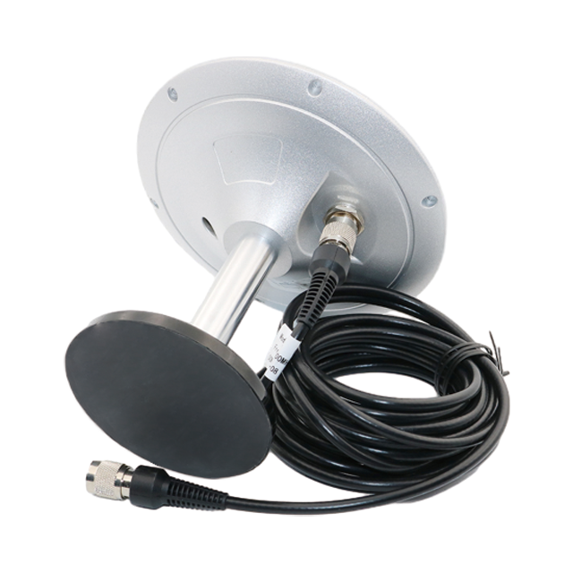
Saltwater is one of the most damaging factors. Saltwater is highly corrosive and can attack the metal components of the antenna, such as the ground plane, mounting hardware, and connectors. Corrosion can cause poor electrical contact, leading to signal loss and increased noise. Even with corrosion - resistant materials, such as stainless steel or aluminum alloys, prolonged exposure to saltwater can eventually cause damage. For example, the connectors used to attach the antenna to the receiver can become corroded, resulting in a poor connection that degrades the signal quality. To mitigate this, manufacturers often use specialized coatings, such as chrome plating or ceramic coatings, on metal components. However, these coatings can wear off over time, especially in areas with high mechanical stress, leaving the underlying metal vulnerable to corrosion.
High humidity is another challenge. Moisture can penetrate the enclosure, even if it meets the IP67 standard, especially if there are small cracks or gaps in the enclosure or around the connectors. Once inside, moisture can cause short - circuits in the RF front - end circuits, damage the dielectric substrate of the antenna elements, and promote the growth of mold and mildew. Mold and mildew can cover the antenna elements, reducing their ability to capture signals and increasing the antenna's noise figure. To prevent moisture ingress, manufacturers use gaskets and seals around the enclosure and connectors. However, these gaskets and seals can degrade over time due to exposure to UV radiation and extreme temperatures, losing their effectiveness.
Extreme temperatures also pose a threat to the antenna's performance. In hot climates, the temperature inside the enclosure can rise to levels that exceed the operating temperature range of the electronic components, such as the LNA and filters. High temperatures can cause the components to malfunction, reduce their gain, and increase their noise figure. In cold climates, the dielectric substrate of the antenna elements can become brittle, leading to cracks that alter the antenna's resonant frequency. Additionally, the expansion and contraction of materials due to temperature changes can cause the enclosure to warp, creating gaps that allow moisture and saltwater to enter. To address temperature - related issues, manufacturers may use thermal management techniques, such as heat sinks or thermal insulation, inside the enclosure. However, these techniques add complexity and weight to the antenna, which can be a disadvantage in marine applications where space and weight are often limited.
Mechanical vibrations from the vessel's engine, waves, and wind can also damage the antenna. The constant vibration can loosen the mounting hardware, causing the antenna to shift position and lose its clear view of the sky. It can also damage the internal components, such as the solder joints between the antenna elements and the RF front - end circuits. Over time, vibration can lead to fatigue failure of the materials, reducing the antenna's lifespan. To improve vibration resistance, manufacturers use vibration - dampening materials in the mounting hardware and design the internal components to be more robust. However, these measures can increase the cost and weight of the antenna, making it less suitable for smaller vessels.
5.1 Key Applications
5.1.1 Commercial Shipping
Commercial shipping is one of the largest and most important applications of multi - band GNSS marine antennas. Modern commercial vessels, such as container ships, tankers, and bulk carriers, rely heavily on accurate navigation to transport goods safely and efficiently across the world's oceans. Multi - band GNSS marine antennas provide the high - accuracy positioning required for route planning, collision avoidance, and berthing operations.
Route planning is a critical aspect of commercial shipping. By using accurate positioning data from multi - band GNSS antennas, ship operators can plan the most efficient routes, taking into account factors such as weather conditions, sea currents, and the location of other vessels. This helps to reduce fuel consumption, minimize travel time, and lower operational costs. For example, a container ship traveling from Shanghai to Rotterdam can use multi - band GNSS positioning to avoid areas with strong headwinds or rough seas, which would otherwise increase fuel usage and delay the arrival time.
Collision avoidance is another essential application. The International Regulations for Preventing Collisions at Sea (COLREGs) require vessels to maintain a safe distance from other vessels and avoid collisions. Multi - band GNSS marine antennas provide real - time positioning data that is integrated into the vessel's Automatic Identification System (AIS). AIS uses this data to track the position, speed, and course of nearby vessels, allowing the ship's crew to identify potential collision risks and take appropriate action. The high accuracy of multi - band GNSS positioning ensures that the AIS data is reliable, enabling the crew to make informed decisions in a timely manner.
Berthing operations also benefit from the accuracy of multi - band GNSS marine antennas. When a vessel is approaching a port or a dock, it needs to maneuver with extreme precision to avoid colliding with the dock or other vessels. Multi - band GNSS antennas provide the precise positioning data required for the ship's navigation system to control the thrusters and rudders, ensuring a smooth and safe berthing process. In some cases, multi - band GNSS is even used in automated berthing systems, where the vessel is controlled by a computer that uses the positioning data to maneuver the ship without human intervention.
5.1.2 Offshore Energy Industry
The offshore energy industry, which includes offshore oil and gas exploration and production, and offshore wind energy, is another major user of multi - band GNSS marine antennas. These industries require highly accurate positioning for a wide range of operations, from the installation of offshore platforms to the maintenance of subsea equipment.
In offshore oil and gas exploration, multi - band GNSS marine antennas are used to position seismic survey vessels. Seismic surveys involve sending sound waves into the seabed to map the geological structures below, which helps to identify potential oil and gas reserves. The positioning of the seismic survey vessel is critical for ensuring that the survey data is accurate and can be used to create detailed maps of the seabed. Multi - band GNSS antennas provide the high - accuracy positioning required to keep the vessel on the correct survey line, even in rough seas or areas with limited satellite visibility.
During the installation of offshore oil and gas platforms, multi - band GNSS marine antennas are used to position the platform and the installation vessels. The platform needs to be placed in a precise location on the seabed to ensure that it is stable and can access the oil or gas reserves. The installation vessels, which are used to transport and place the platform components, rely on multi - band GNSS positioning to maneuver the components into the correct position. The accuracy of the positioning data is essential for ensuring that the platform is installed safely and efficiently, reducing the risk of delays and cost overruns.
Offshore wind energy is a rapidly growing sector that also depends on multi - band GNSS marine antennas. The installation of offshore wind turbines requires precise positioning to ensure that the turbines are placed in areas with strong and consistent winds, and that they are spaced correctly to avoid interference with each other. Multi - band GNSS antennas are used to position the installation vessels and the wind turbine components during the installation process. After installation, the antennas are used to monitor the position of the turbines, which can shift over time due to the effects of waves and currents. This monitoring helps to ensure the safety and efficiency of the wind farm, as any significant shift in the turbine's position can affect its performance and increase the risk of damage.
In addition, multi - band GNSS marine antennas are used in the maintenance of offshore energy infrastructure. Subsea pipelines, cables, and other equipment need to be inspected and maintained regularly to ensure their integrity. Inspection vessels equipped with multi - band GNSS antennas use the positioning data to navigate to the exact location of the subsea equipment and to control remotely operated vehicles (ROVs) that perform the inspection and maintenance tasks. The high accuracy of the positioning data ensures that the ROVs can reach the target area precisely, reducing the time and cost of the maintenance operations.
5.1.3 Autonomous Marine Vessels
The development of autonomous marine vessels (AMVs) is one of the most exciting trends in the marine industry, and multi - band GNSS marine antennas are a key enabling technology. AMVs, which include autonomous ships, underwater vehicles (AUVs), and unmanned surface vessels (USVs), require extremely accurate and reliable positioning to operate safely and autonomously.
Autonomous ships are designed to navigate and operate without human intervention. They rely on a combination of sensors, including multi - band GNSS antennas, to perceive their environment and make navigation decisions. The high - accuracy positioning data from the multi - band GNSS antenna is used to determine the ship's position, speed, and course, which is integrated with data from other sensors such as radar, lidar, and cameras to avoid obstacles and follow the planned route. For example, an autonomous container ship traveling from a port to a offshore terminal can use multi - band GNSS positioning to stay on course, while using radar and lidar to detect and avoid other vessels, icebergs, or other obstacles.
AUVs are used for a wide range of applications, such as oceanographic research, underwater mapping, and military surveillance. These vehicles operate underwater, but they still need to surface periodically to receive GNSS signals and update their position. Multi - band GNSS marine antennas are used on the surface of the AUV to capture the signals, providing the high - accuracy positioning required to ensure that the AUV's underwater missions are carried out correctly. For example, an AUV used for underwater mapping can use multi - band GNSS positioning to determine its position when it surfaces, which is then used to correct the position data collected during the underwater mapping mission. This ensures that the resulting bathymetric maps are accurate and reliable.
USVs are unmanned vessels that operate on the surface of the water. They are used for applications such as environmental monitoring, border patrol, and search and rescue. USVs rely on multi - band GNSS marine antennas for positioning, as they need to navigate to specific locations and perform tasks without human intervention. The high reliability of multi - band GNSS positioning ensures that the USV can operate in challenging environments, such as coastal areas with strong currents or near - shore regions with limited satellite visibility. For example, a USV used for environmental monitoring can use multi - band GNSS positioning to navigate to a specific area of the ocean, collect water samples, and then return to the shore, all without human control.
5.2 Future Trends
5.2.1 Integration with Other Sensor Technologies
One of the key future trends in multi - band GNSS marine antennas is the integration with other sensor technologies, such as inertial measurement units (IMUs), radar, lidar, and cameras. This integration will create a more robust and reliable navigation system that can operate in even the most challenging marine environments.
IMUs are devices that measure the linear acceleration and angular velocity of a vessel. They can provide positioning data when GNSS signals are unavailable, such as when the antenna is blocked by a large wave or a nearby building. By integrating multi - band GNSS with an IMU, the navigation system can use the GNSS data to calibrate the IMU when signals are available, and then use the IMU data to continue providing positioning when GNSS signals are lost. This hybrid navigation system will significantly improve the reliability of positioning in areas with intermittent GNSS coverage, such as coastal cities or narrow straits.
Radar and lidar are used to detect obstacles and other vessels in the vicinity of the ship. By integrating multi - band GNSS with radar and lidar, the navigation system can combine the positioning data from the GNSS antenna with the obstacle detection data from the radar and lidar to create a more comprehensive view of the ship's environment. This will enable the system to make more informed navigation decisions, such as avoiding a collision with a nearby vessel or navigating around a shallow area. For example, if the radar detects a vessel that is on a collision course, the navigation system can use the GNSS positioning data to calculate the distance between the two vessels and determine the best course of action to avoid the collision.
Cameras can be used to capture visual images of the ship's surroundings, which can be used to identify objects and verify the data from other sensors. By integrating multi - band GNSS with cameras, the navigation system can use the GNSS positioning data to tag the visual images with the exact location where they were captured. This can be useful for applications such as port security, where the images can be used to monitor the movement of vessels and cargo, and for search and rescue operations, where the images can be used to locate missing persons or objects.
5.2.2 Miniaturization and Low - Power Consumption
As the marine industry moves towards smaller and more efficient vessels, there is a growing demand for miniaturized multi - band GNSS marine antennas with low power consumption. Miniaturization will allow the antennas to be installed on smaller vessels, such as small fishing boats, recreational yachts, and USVs, where space is limited. Low power consumption will extend the battery life of these vessels, which is especially important for USVs and AUVs that operate for long periods without being recharged.
Advancements in microelectronics and materials science are driving the miniaturization of multi - band GNSS marine antennas. For example, the development of microstrip patch antennas with smaller dimensions and higher efficiency is enabling the creation of compact antennas that can support multiple frequency bands. In addition, the use of new materials, such as carbon nanotubes and graphene, is helping to reduce the size and weight of the antenna elements while maintaining their performance.
Low - power consumption is being achieved through the development of energy - efficient RF front - end components and signal processing algorithms. For example, the use of low - power LNAs and filters that consume less energy while still providing high gain and low noise figure is reducing the overall power consumption of the antenna system. In addition, advanced signal processing algorithms that can reduce the number of computations required to process the GNSS signals are also helping to lower power consumption. These algorithms can be implemented using field - programmable gate arrays (FPGAs) or application - specific integrated circuits (ASICs) that are designed for low - power operation.
5.2.3 Support for New GNSS Constellations and Frequency Bands
As new GNSS constellations and frequency bands are developed, multi - band GNSS marine antennas will need to evolve to support these new systems. This will enable the antennas to provide even more accurate and reliable positioning services, as well as expand their coverage to new regions of the world.
One of the most significant new GNSS constellations is the BeiDou Navigation Satellite System (BDS) developed by China. BDS is currently in the process of expanding its global coverage, and it offers several new frequency bands that can be used for high - accuracy positioning. Multi - band GNSS marine antennas that support BDS will be able to take advantage of these new frequency bands, providing improved positioning accuracy in areas where BDS has strong coverage, such as Asia and the Pacific region.
Another new GNSS constellation is the Indian Regional Navigation Satellite System (IRNSS), also known as NavIC. IRNSS is designed to provide positioning services in the Indian subcontinent and surrounding regions, and it operates on several unique frequency bands. Multi - band GNSS marine antennas that support IRNSS will be able to provide more reliable positioning in these regions, which is important for the growing marine industry in India and neighboring countries.
In addition to new constellations, new frequency bands are also being added to existing GNSS systems. For example, the GPS system is planning to add a new frequency band, L1C, which is designed to improve the accuracy and reliability of positioning in urban and coastal environments. Multi - band GNSS marine antennas that support L1C will be able to provide better performance in these challenging environments, where multipath interference is a major issue.
To support these new constellations and frequency bands, multi - band GNSS marine antenna manufacturers need to adopt a flexible and scalable design approach. This involves using modular antenna elements and RF front - end components that can be easily modified or upgraded to support new frequency bands. For example, instead of designing a fixed set of antenna elements for specific frequency bands, manufacturers can use configurable patch antenna arrays that can be tuned to different frequencies through software or hardware adjustments. This modular design not only reduces the time and cost of developing new antennas but also allows existing antennas to be upgraded in the field to support new GNSS systems, extending their lifespan and reducing waste.
In addition, the signal processing algorithms used in multi - band GNSS marine antennas need to be updated to handle the new signals from these constellations and frequency bands. New algorithms may be required to decode the unique PRN codes and data formats used by new GNSS constellations, such as BDS and IRNSS. These algorithms also need to be optimized to combine signals from multiple constellations and frequency bands effectively, maximizing the accuracy and reliability of the positioning data. For example, algorithms that use advanced fusion techniques, such as Kalman filtering or particle filtering, can combine the strengths of different GNSS signals to provide a more robust position fix, even in challenging environments.
5.2.4 Enhanced Anti - Jamming Capabilities
With the increasing use of GNSS in critical marine applications, the risk of intentional jamming and spoofing attacks is also growing. Jamming involves transmitting strong radio signals to disrupt the reception of GNSS signals, while spoofing involves transmitting fake GNSS signals to deceive the receiver into calculating an incorrect position. These attacks can have severe consequences for marine vessels, such as causing collisions, grounding, or the loss of valuable cargo. To address this threat, future multi - band GNSS marine antennas will need to incorporate enhanced anti - jamming capabilities.
One of the key technologies for anti - jamming is adaptive beamforming. Adaptive beamforming uses an array of antenna elements to focus the antenna's radiation pattern on the desired GNSS satellites while nulling out the direction of the jamming signal. This allows the antenna to receive the weak GNSS signals even in the presence of strong jamming. For example, if a jamming signal is coming from a specific direction, the adaptive beamforming algorithm can adjust the phase and amplitude of the signals received by each antenna element to create a null in that direction, effectively blocking the jamming signal.
Another anti - jamming technology is the use of spread - spectrum techniques. GNSS signals already use spread - spectrum modulation, which spreads the signal over a wide frequency band, making it more resistant to narrow - band jamming. Future multi - band GNSS marine antennas can further enhance this resistance by using wider bandwidths or more advanced spread - spectrum codes. In addition, the use of frequency hopping, where the antenna switches between different frequency bands in a pseudo - random pattern, can make it more difficult for jammers to target the GNSS signals.
Spoofing detection is another important aspect of enhanced security. Multi - band GNSS marine antennas can use the differences between signals from multiple frequency bands and constellations to detect spoofing. For example, if a spoofed signal is transmitted on one frequency band but not on others, the receiver can compare the position calculated from the spoofed band with the position calculated from the other bands and identify the discrepancy. Advanced signal processing algorithms can also analyze the characteristics of the received signals, such as their signal strength, phase, and Doppler shift, to detect anomalies that indicate spoofing.
Conclusion
Multi - band GNSS marine antennas have emerged as a critical technology in the marine industry, providing the high - accuracy, reliable positioning required for a wide range of applications, from commercial shipping to offshore energy operations and autonomous marine vessels. Throughout this comprehensive overview, we have explored the key aspects of these antennas, including their design and construction, working principles, advantages and challenges, applications, and future trends.
In terms of design and construction, multi - band GNSS marine antennas are complex systems that require careful selection and configuration of antenna elements, such as stacked patch antennas and crossed dipole antennas, to support multiple frequency bands. The RF front - end, with its low - noise amplifiers and specialized filters, is essential for amplifying weak GNSS signals and rejecting interference. The enclosure and mounting of the antenna are also designed to withstand the harsh marine environment, with waterproof, corrosion - resistant materials and secure mounting hardware ensuring the antenna's durability and optimal signal reception.
The working principles of multi - band GNSS marine antennas revolve around the reception of electromagnetic signals from multiple GNSS constellations and frequency bands, the calculation of position using code - phase ranging and trilateration, and the mitigation of multipath interference through techniques like circular polarization and antenna arrays. These principles enable the antenna to provide accurate and reliable positioning even in challenging marine conditions.
The advantages of multi - band GNSS marine antennas are significant. They offer enhanced positioning accuracy by mitigating errors such as ionospheric delay and multipath interference, increased signal reliability by switching between frequency bands when signals are blocked or weakened, and support for multiple GNSS constellations, which increases the number of available satellites and improves coverage. However, these antennas also face challenges, including interference from other radio systems, the complexity of design and calibration, and the need to withstand the harsh marine environment's corrosive and dynamic conditions.
The applications of multi - band GNSS marine antennas are diverse and growing. In commercial shipping, they are used for route planning, collision avoidance, and berthing operations, helping to improve efficiency and safety. In the offshore energy industry, they play a crucial role in the positioning of seismic survey vessels, offshore platforms, and wind turbines, as well as the maintenance of subsea infrastructure. For autonomous marine vessels, they are a key enabling technology, providing the precise positioning required for safe and autonomous operation.
Looking to the future, multi - band GNSS marine antennas are poised to undergo significant advancements. Integration with other sensor technologies, such as IMUs, radar, and cameras, will create more robust hybrid navigation systems that can operate in even the most challenging environments. Miniaturization and low - power consumption will make these antennas more accessible for smaller vessels and unmanned systems, expanding their range of applications. Support for new GNSS constellations and frequency bands will further improve accuracy and coverage, while enhanced anti - jamming capabilities will address the growing threat of intentional interference.
As the marine industry continues to evolve, driven by factors such as global trade growth, the expansion of offshore renewable energy, and the development of autonomous technologies, the demand for multi - band GNSS marine antennas will only increase. Manufacturers will need to continue innovating to overcome the existing challenges, such as reducing design complexity and improving environmental durability, while also keeping pace with new technological advancements and regulatory requirements.
In conclusion, multi - band GNSS marine antennas are an indispensable component of modern marine navigation and operations. Their ability to provide accurate, reliable positioning in the harsh marine environment makes them essential for ensuring the safety, efficiency, and sustainability of marine activities. As technology continues to advance, these antennas will play an even more critical role in shaping the future of the marine industry, enabling new applications and unlocking new possibilities for exploration, commerce, and environmental protection on the world's oceans.

 86 0755 2819 9597
Lucy Yang | lucy.y@toxutech.com
Nicole Li | nicole@toxutech.com
Dotty Zhao | sales04@toxutech.com
Global Business Director / Sales Team / Global Operations


 En
En Cn
Cn Korean
 Home >


