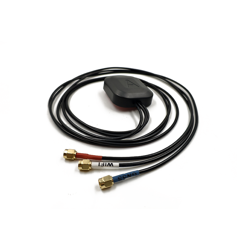
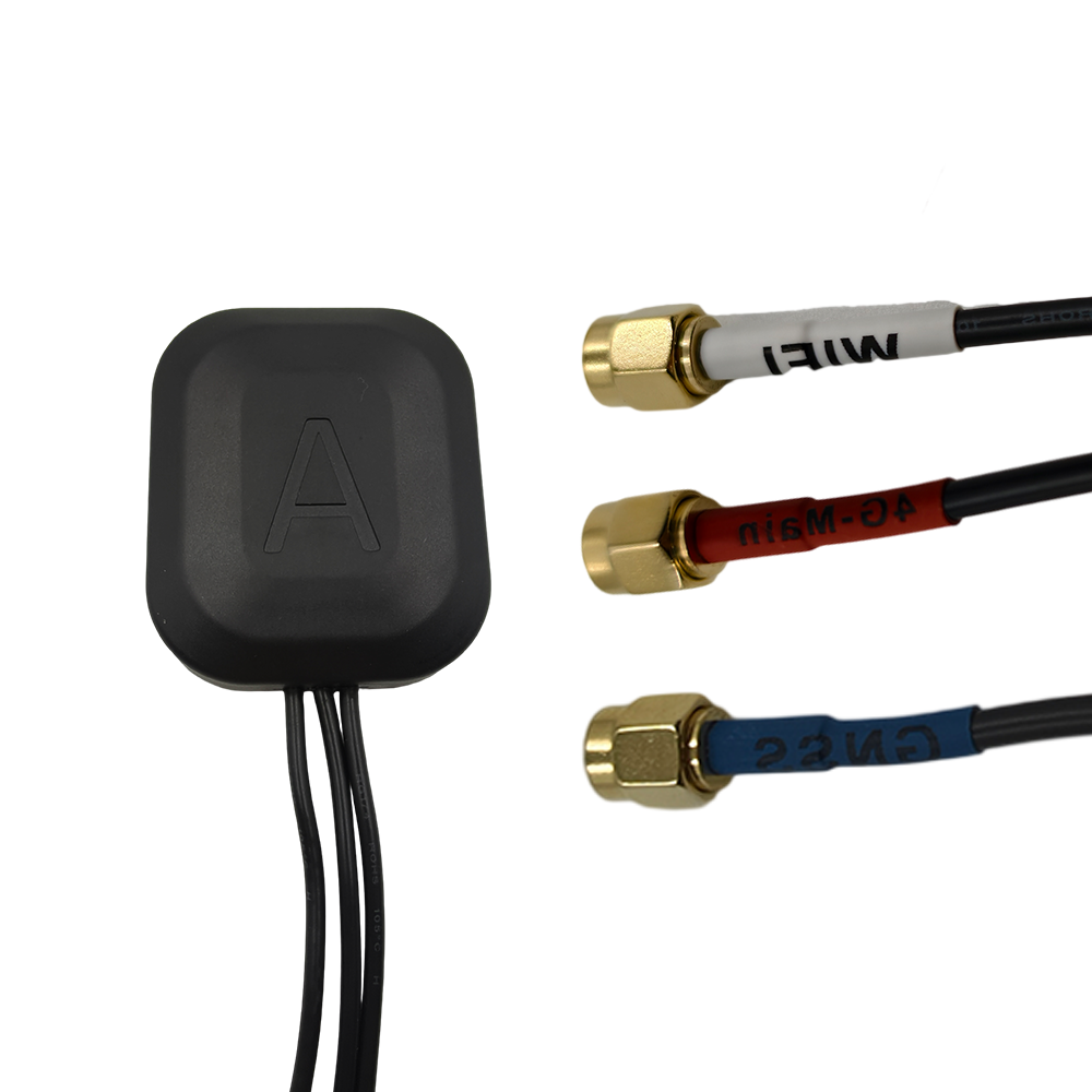
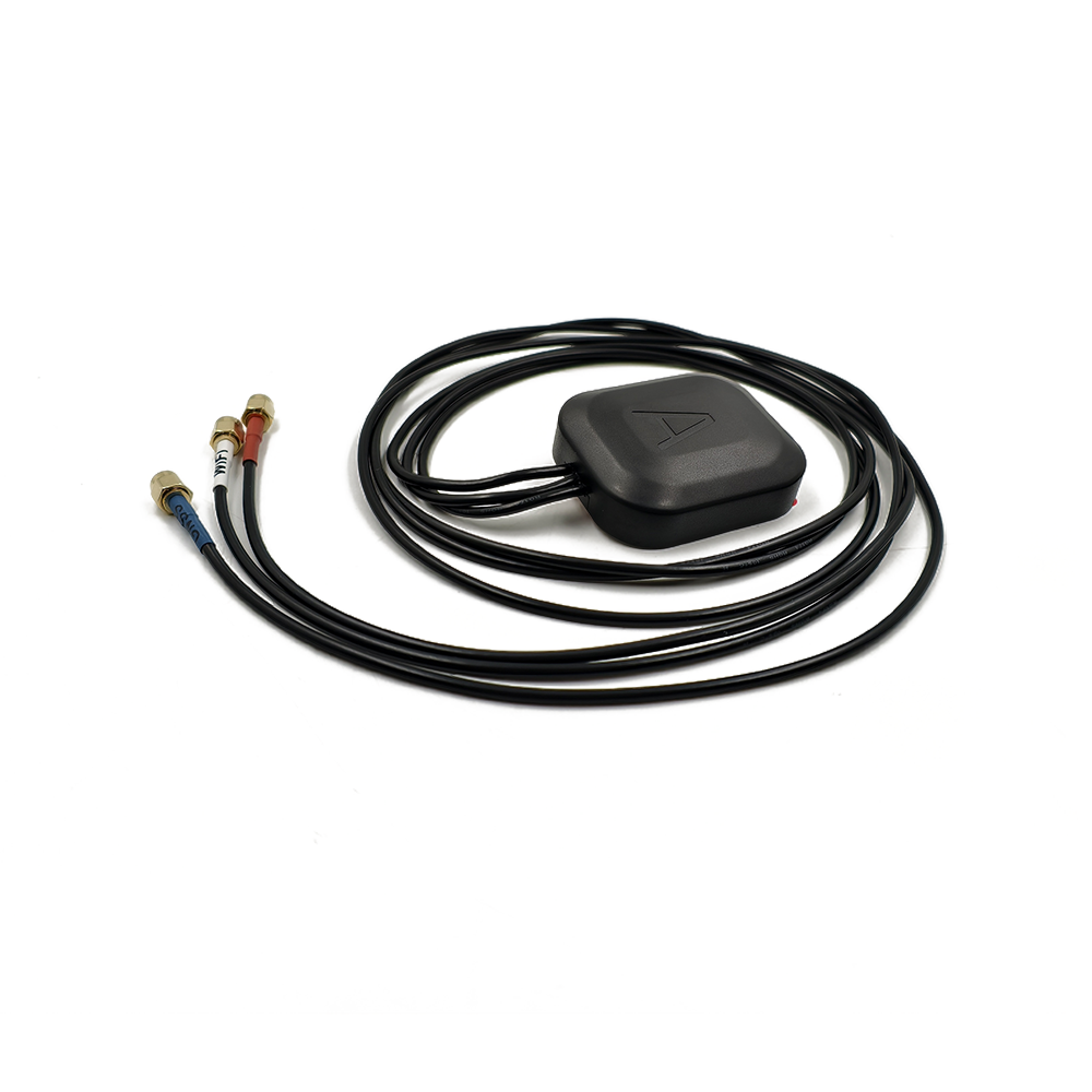
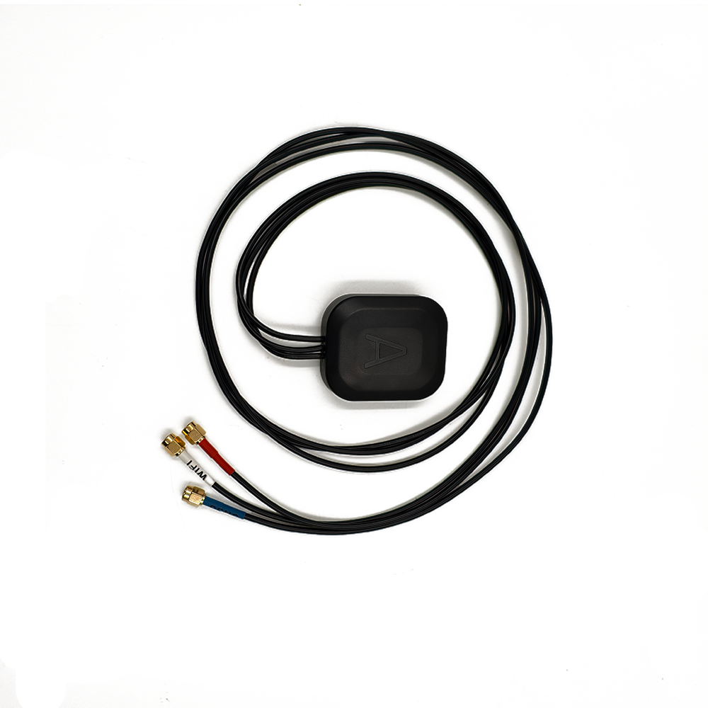
Combo Antenna Combo Antenna

Language
Built-in RTK GPS Antenna
GNSS Car Antenna
GNSS Car Antenna

GPS & GNSS Antenna

Home >  GPS & GNSS Antenna > 

Multi-Band GNSS Antenna

The Global Navigation Satellite System (GNSS) ecosystem is in the midst of a renaissance, transitioning from reliance on a single system (GPS) to a robust, multi-constellation reality. This paradigm shift, often termed "GNSS interoperability," has been made possible by a critical hardware component that acts as the gateway to this new world of precision: the multi-band GNSS antenna. This antenna is the unsung hero of modern high-precision positioning, the crucial first element that captures the expanded universe of satellite signals, enabling everything from faster consumer navigation to centimeter-level autonomous operations.


Leave a message Contact

Fill in your email address

Or you can continue to download without filling in

Overview

A multi-band GNSS antenna is a sophisticated receiver element specifically engineered to operate across multiple designated radio frequency bands used by global and regional navigation satellite systems. Unlike a simple single-band L1 antenna found in early personal navigation devices, a multi-band antenna is designed to be inherently wideband or multi-resonant, capable of efficiently receiving signals from the full suite of available constellations:

GPS (USA): L1 (1575.42 MHz), L2 (1227.60 MHz), L5 (1176.45 MHz)

GLONASS (Russia): L1 (1602 MHz), L2 (1246 MHz), L3 (1202.025 MHz)

Galileo (EU): E1 (1575.42 MHz), E5a (1176.45 MHz), E5b (1207.14 MHz), E6 (1278.75 MHz)

BeiDou (China): B1 (1561.098 MHz), B2 (1207.14 MHz), B3 (1268.52 MHz)

Regional Systems (QZSS, NavIC): Also broadcasting on L1, L5, and S-band.

The impetus for this technological evolution is the relentless demand for greater accuracy, integrity, and reliability. Single-band receivers are fundamentally constrained by their inability to directly measure and thus eliminate the largest source of error in GNSS: the signal delay caused by the Earth's ionosphere. These receivers must rely on imperfect dual-frequency models or kludge corrections, limiting their real-world accuracy to meter-level.

Multi-band technology shatters this limitation by leveraging a fundamental property of radio wave propagation: ionospheric delay is frequency-dependent. By measuring the same satellite signal on two or more distinct frequencies, a receiver can directly calculate the precise delay and remove it from the measurement, a process known as forming the ionosphere-free combination. This capability, however, is entirely contingent on the antenna's ability to receive these multiple frequencies with high fidelity and minimal distortion. The most advanced multi-band receiver is useless if the antenna cannot provide it with clean, coherent signals from all target bands.

The benefits are profound and extend far beyond basic ionospheric correction:

Faster and More Robust Ambiguity Resolution: For Real-Time Kinematic (RTK) and Precise Point Positioning (PPP) techniques, multi-band observations provide a wealth of data. This allows the receiver's processing engine to resolve the integer number of carrier-phase wavelengths (the "ambiguity") much more quickly and maintain this fixed solution with greater resilience against signal obstructions and atmospheric disturbances.

Enhanced Signal Redundancy and System Integrity: Access to multiple signals from multiple constellations on multiple bands creates a deeply redundant system. If a signal on one frequency is lost due to interference, jamming, or physical obstruction, the receiver can seamlessly continue processing on another frequency from the same or a different satellite, ensuring uninterrupted service. This is critical for safety-of-life applications in aviation, automotive, and marine domains.

Access to Modernized Signals: New civil signals on bands like L5 and E5 are more powerful, have longer spreading codes, and are broadcast in internationally protected aeronautical radionavigation service (ARNS) bands. These signals are more robust, easier to acquire and track, and significantly more resistant to jamming and spoofing attacks. A multi-band antenna is the key to unlocking these modernized capabilities.

In essence, the multi-band GNSS antenna is the foundational sensor upon which the entire edifice of modern high-precision positioning is built. It transforms the receiver from a passive navigator into an active, high-integrity sensor. From enabling the auto-steering of agricultural machinery and the precise guidance of construction equipment to forming the absolute positioning backbone for autonomous vehicles and unmanned aerial systems, the multi-band antenna is the indispensable enabler of the autonomy revolution. It represents not merely an incremental improvement but a fundamental shift in the capabilities and potential of satellite-based positioning.


Design and Construction

The design and construction of a multi-band GNSS antenna represent a significant leap in complexity and sophistication compared to a single-band design. It is an exercise in advanced electromagnetic engineering, material science, and precision manufacturing, where every component must be optimized to achieve consistent, high-performance operation across a wide spectrum of frequencies without introducing distortions that could corrupt precise measurements.

Core Architectural Components and Techniques:

The Radiating Element: Beyond the Simple Patch

The heart of the antenna is the radiating element. While the microstrip patch antenna remains the dominant topology due to its low profile and conformal nature, a standard single patch is inherently narrowband. To achieve multi-band operation, designers employ several advanced techniques:

Stacked Patches: This is the most prevalent and effective design for high-precision multi-band antennas. It consists of two or more patch elements, concentrically stacked and separated by layers of dielectric substrate. The larger, lower patch is electromagnetically coupled and tuned to resonate at the lower frequency bands (e.g., L2/L5/E5/B2), while the smaller, upper patch is tuned to the higher frequency bands (e.g., L1/E1/B1). This allows each patch to operate near its optimal resonant point, providing excellent performance across all desired bands without severe compromise.

Slot-Coupled and Aperture-Coupled Feeds: Instead of a direct-probe feed, which can introduce unwanted inductance and limit bandwidth, high-end designs use coupling through a slot or aperture in the ground plane. This technique allows for better impedance matching, broader bandwidth, and reduces parasitic radiation from the feed network, which is crucial for maintaining a pure phase responsea non-negotiable requirement for carrier-phase positioning.

Advanced Dielectric Materials: The choice of substrate material is critical. Designers use substrates with a low dielectric constant (εr) and low loss tangent. A low εr allows for a physically larger patch for a given frequency, which inherently increases bandwidth. A low loss tangent minimizes signal attenuation within the substrate itself. Materials like ceramic-loaded PTFE (Teflon) or specialized foams are common.

The Ground Plane: The Silent Director

A solid, finite ground plane is mandatory. It performs several vital functions: it creates the antenna's directional pattern (hemispherical coverage), provides a stable electrical reference for the radiating element, and acts as a shield, rejecting noise and multipath signals arriving from below the horizon. The size of the ground plane is a key design parameter; a larger diameter improves gain roll-off at low elevations, enhancing multipath rejection.

The Feed Network: The Impedance Matcher

This is arguably one of the most challenging aspects of the design. The feed network must transfer energy from the single output connector to the radiating element(s) while maintaining a precise 50-ohm impedance match across all target frequency bands. For stacked patches, this often involves a complex arrangement of feeds to excite each patch optimally. Any imperfection here can result in return loss (VSWR), phase delays, and amplitude variations that differ by frequency, destroying the geometric integrity of the measurements.

Phase Center Stability: The Benchmark of Precision

For high-precision applications, the stability of the antenna's Phase Center is paramount. The phase center is the electrical point from which the signal is received; it is the virtual reference point for all carrier-phase measurements.

Phase Center Offset (PCO): The vector between the antenna's physical reference point (Antenna Reference Point - ARP) and its average phase center.

Phase Center Variation (PCV): The movement of the phase center as a function of the elevation and azimuth angle of the incoming satellite signal.

A high-quality multi-band antenna is meticulously designed to have minimal PCV. Its PCO and PCV are rigorously measured for each frequency in an anechoic chamber, and these calibration values (published in ANTEX files) are used by processing software to correct for antenna-specific biases, ensuring millimeter-level accuracy.

Integrated Active Components: LNA and Filtering

Integrated within the antenna housing is a Low-Noise Amplifier (LNA). Its purpose is to amplify the exceedingly weak signals from space (around -130 dBm) before they suffer loss in the coaxial cable connecting the antenna to the receiver. This preserves the critical Signal-to-Noise Ratio (SNR). The LNA must have an exceptionally low noise figure and high linearity.

Equally important are the bandpass filters placed before the LNA. These filters are tuned to the specific GNSS bands and are essential for rejecting powerful out-of-band interference from cellular, WiFi, and radio transmitters, which could desensitize or overload the receiver.

Radome and Environmental Sealing

The entire assembly is protected by a radome. This cover must be made from a material that is virtually transparent to RF signals across the entire operational bandwidth (e.g., high-quality polycarbonate or ceramic-filled plastic). The assembly is typically sealed to an IP67 rating or higher to protect the delicate internal components from moisture, dust, UV radiation, and physical impact.

In summary, the construction of a multi-band GNSS antenna is a holistic endeavor where electromagnetic performance, mechanical robustness, and environmental protection are inextricably linked. It is a precision instrument where the choice of materials, the geometry of the patches, the design of the feed, and the quality of the active components all converge to define its ultimate performance as the critical first link in the high-precision positioning chain.


Working Principles

The working principle of a multi-band GNSS antenna extends far beyond the basic function of electromagnetic transduction. Its core mission is to act as a wideband, spatially selective filter that captures a broad spectrum of signals with high fidelity while preserving the critical geometric relationships between them. The integrity of the signal's "phase" is the paramount concern, as this is the observable that enables centimeter-level accuracy.

Fundamental Transduction and Bandwidth Enhancement

At its most fundamental level, the antenna operates on the principle of resonance. The conductive patch element, excited by the feed network, oscillates at specific frequencies, efficiently coupling energy from incoming electromagnetic waves into electrical currents. A single patch has a natural, but narrow, resonant frequency.

The stacked-patch design creates multiple resonant points. The lower patch, being larger, has a lower fundamental resonant frequency, optimally tuned for bands like L5 and L2. The smaller, upper patch has a higher resonant frequency, tuned for L1 and E1. The electromagnetic coupling between these patches, through their fringing fields, allows for a combined impedance bandwidth that cleanly encompasses all target frequencies. The use of low-permittivity, thick substrates further widens this bandwidth by reducing the electrical "Q" factor of the patches.

Phase Stability: The Cornerstone of Precision

For standard navigation, the amplitude (strength) of the signal is the primary concern. For high-precision carrier-phase positioning, the phase of the signal is everything. The receiver measures the distance to the satellite by tracking the phase of the carrier wave, which has a wavelength of just 19 cm (L1) and 24 cm (L2). To achieve centimeter-level accuracy, this phase measurement must be stable to a small fraction of a wavelength.

The antenna must introduce minimal distortion to this phase. Any movement of the antenna's phase center as a satellite moves across the sky (Phase Center Variation - PCV) introduces a measurable error. A well-designed multi-band antenna minimizes PCV through symmetrical, precise construction and a stable feed network. Furthermore, the group delaythe time it takes for different frequency components to pass through the antennamust be consistent. Inconsistent group delay across different bands would corrupt the receiver's ability to perform precise ionospheric delay calculations, as the timing relationships between frequencies would be skewed.

Spatial Filtering: The Radiation Pattern

The antenna's radiation pattern defines its gain as a function of direction. The ideal pattern for a GNSS antenna is highly directional in the upward hemisphere:

High gain at high elevation angles (from about 10 to 90 degrees), where direct, line-of-sight satellite signals arrive.

Rapidly falling gain (roll-off) at low elevation angles (below 10 degrees).

Very low gain (nulls) below the horizon, to reject multipath signals reflected from the ground and nearby objects.

This shaped pattern is achieved through the combination of the patch element and the finite ground plane. A key design challenge for a multi-band antenna is to maintain this desirable pattern consistently across all its operating bands. If the pattern is significantly different for L1 and L5, it could introduce frequency-dependent biases in the measurements, as the same satellite signal would be received with different strengths depending on the frequency.

The Active System: LNA and Spectral Filtering

The integrated Low-Noise Amplifier (LNA) is an active part of the antenna's function. Its primary role is to provide gain to overcome the losses in the coaxial cable. By amplifying the signal at the source (before the cable), it preserves the Signal-to-Noise Ratio (SNR). A high SNR is critical for reliable signal tracking, especially under weak signal conditions or when tracking the longer, more complex codes of modernized signals like L5.

The bandpass filters are the spectral gatekeepers. They are designed with very sharp cut-offs to create a "passband" that includes all GNSS frequencies (e.g., ~1160-1300 MHz and ~1550-1610 MHz) while aggressively rejecting all other frequencies. This is crucial because powerful out-of-band signals from nearby transmitters (e.g., 4G/5G base stations, VHF radios) could easily overload the sensitive LNA and receiver front-end, causing a complete loss of lock on all GNSS signals.

In essence, the working principle of a multi-band GNSS antenna is to perform a series of critical, simultaneous functions: wideband reception of right-hand circularly polarized signals, spatial filtering to suppress multipath, spectral filtering to reject interference, low-noise amplification to preserve SNR, and all while maintaining ultra-stable phase and group delay characteristics across all frequencies and directions. It is a sophisticated transducer that transforms the complex and noisy RF environment into a clean, coherent, and information-rich data stream for the receiver to decode.


Advantages and Challenges

The integration of a multi-band GNSS antenna into a positioning system delivers a transformative set of advantages that fundamentally elevate performance. However, realizing these benefits requires navigating a set of inherent design complexities and practical challenges that influence cost, size, and implementation.

Advantages:

Unprecedented Ionospheric Error Removal: This is the paramount advantage. By providing simultaneous observations on two or more frequencies, the antenna enables the receiver to directly calculate and eliminate the ionospheric delaythe single largest source of error in GNSS. This is a physical measurement, not a model, resulting in a dramatic improvement in standalone positioning accuracy, often reducing error from several meters to submeter levels.

Dramatically Improved RTK/PPP Performance: For high-precision techniques, multi-band observations are a game-changer. The additional observables provide massive redundancy and stronger geometric constraints for the receiver's Kalman filter. This translates to:

Faster Time-To-First-Fix (TTFF): The integer ambiguities can be resolved in seconds instead of minutes.

Enhanced Robustness: The fixed solution is maintained more reliably during periods of moderate signal obstruction, satellite geometry changes, or ionospheric scintillation.

Longer Baseline Capability: Because the spatially correlated ionospheric error is physically eliminated, the distance between a base station and a rover can be extended to 50 km or more while still maintaining centimeter-level accuracy.

Exceptional System Integrity and Redundancy: Access to multiple signals from multiple constellations on multiple bands creates a deeply resilient system. This redundancy is critical for safety-of-life and autonomous applications. If a signal on one frequency is lost due to interference, jamming, or physical obstruction, the receiver can immediately and seamlessly continue processing on another frequency from the same satellite or a different constellation, ensuring continuous and reliable positioning.

Access to Superior Modernized Signals: Multi-band antennas provide access to new civil signals on L5, E5, and B2 bands. These signals offer significant advantages:

Higher Power: Easier to acquire and track in challenging environments.

Longer Codes: Provide better correlation properties and improved multipath resistance.

ARNS Band Protection: L5 and E5a are in the Aeronautical Radionavigation Service band, which is protected from interference, making them more robust.

Pilot Signals: Some modernized signals include a dataless pilot component, which allows for longer coherent integration times in the receiver, significantly improving tracking sensitivity.

Inherently Better Multipath Mitigation: While the antenna's radiation pattern is the first line of defense, the multi-band nature provides additional tools. Advanced receivers can use signal-to-noise ratio (SNR) data and code-phase comparison between frequencies to help detect and mitigate the effects of multipath. Furthermore, the longer wavelength of L5 signals makes them less susceptible to certain types of multipath interference.

Challenges and Limitations:

Design Complexity and High Cost: The engineering required to create an antenna that performs with low PCV and consistent patterns across a wide bandwidth is immense. The use of stacked patches, sophisticated feed networks, high-quality dielectric materials, and rigorous calibration in anechoic chambers drives the manufacturing cost significantly higher than that of a simple single-band patch antenna. This is the primary barrier to widespread adoption.

Size and Form Factor Constraints: Achieving wide bandwidth and stable performance often requires a larger antenna volume. The stacked-patch approach and the use of thick, low-εr substrates inherently result in a larger and heavier antenna compared to a single-layer patch. This can be a critical limiting factor for size-constrained applications like drones, handheld devices, and consumer electronics, though intense R&D is focused on miniaturization.

Power Requirements: The integrated Low-Noise Amplifier (LNA) requires a DC power source, which is typically provided by the receiver through the coaxial cable ("phantom power"). While the power draw is modest (e.g., 3.3V-5V at <50 mA), it is a non-zero consideration for ultra-low-power battery-operated devices where every microwatt-hour counts.

Calibration Dependency: To achieve the highest possible accuracy (sub-centimeter), the calibrated Phase Center Offset (PCO) and Phase Center Variation (PCV) values must be applied in the post-processing or RTK software. Using an antenna without proper calibration, or applying incorrect calibration values, can introduce biases that negate the benefits of multi-frequency processing. This adds a layer of complexity for the end-user.

Management of Intermodulation Products: With the antenna simultaneously receiving a wide range of frequencies, there is a potential for non-linearities in the active components (especially the LNA) to create intermodulation productsfalse signals generated by the mixing of two or more strong incoming signals. While filtering mitigates this, careful LNA design is required to maintain linearity.

In conclusion, the advantages of multi-band antennas are so profound for any application requiring high accuracy, reliability, and integrity that they are becoming the standard for professional, scientific, and autonomous use. The challenges are primarily related to cost, size, and power, which are being actively addressed through continuous innovation in materials, design tools, and manufacturing processes.


Applications and Future Trends

The capabilities unlocked by multi-band GNSS antennas have catalyzed a revolution across industries that depend on precise, reliable, and continuous positioning. They are the enabling hardware that allows algorithms and systems to deliver centimeter-level accuracy in real-time, transforming a wide array of traditional and emerging applications.

Key Applications:

Precision Agriculture: This is one of the largest and most mature markets. Multi-band RTK systems guide tractors, harvesters, and sprayers with 2-3 cm accuracy, enabling hands-free operation 24/7. This enables auto-steering, variable rate application (VRA) of inputs, and yield mapping, leading to massive gains in efficiency, reduced input costs, and increased yields. The robustness of multi-band allows operation to continue reliably even with vehicle movement and partial signal blockages.

Professional Surveying, Mapping, and GIS: The standard tool for the modern surveyor. Multi-band GNSS provides faster initialization times, the ability to work in more challenging environments (under light tree cover, urban areas), and longer baseline lengths between base and rover. It is essential for cadastral surveying, construction site preparation, topographic mapping, and GIS data collection.

Unmanned Aerial Vehicles (UAVs) and Aerial Mapping: Multi-band PPK (Post-Processed Kinematic) and RTK have revolutionized drone-based photogrammetry and LiDAR mapping. By providing a precise geotag for every aerial image (to within 1-2 cm), the technology eliminates or drastically reduces the need for ground control points (GCPs). This slashes fieldwork time by up to 90% and enables the rapid creation of highly accurate orthomosaics, digital surface models (DSMs), and 3D point clouds.

Autonomous Systems and Robotics:

Automotive: Multi-band GNSS is a critical sensor for autonomous vehicles (AVs) and advanced driver-assistance systems (ADAS). It provides the absolute position anchor that is fused with LiDAR, radar, and cameras to create a failsafe navigation system. Its ability to mitigate atmospheric error is crucial for functional safety and meeting stringent automotive standards.

Mobile Robots: Used for autonomous mobile robots (AMRs) in logistics warehouses, last-mile delivery robots, and agricultural robots for weeding and harvesting.

Construction and Machine Control: Bulldozers, graders, and excavators equipped with multi-band GNSS systems can automatically guide their blades and buckets to the exact design grade with centimeter-level precision. This improves efficiency, reduces material waste, eliminates rework, and enhances safety on dynamic construction sites.

Scientific and Structural Monitoring: Used for monitoring tectonic plate movement, volcanic deformation, landslides, and the structural health of large critical infrastructure like dams, bridges, and skyscrapers. The integrity and long-baseline capability of multi-band systems are essential for detecting millimeter-level movements over time.

Aviation and Maritime: For precision approach and landing in aviation (using GBAS and SBAS) and for precision docking, dredging, and waterway navigation in the maritime sector, multi-band antennas providing access to L1/L5 signals are becoming the standard for improved integrity, accuracy, and reliability.

Future Trends:

Miniaturization and Integration for Mass Markets: The relentless drive is towards smaller, lighter, and lower-cost antennas that retain high performance. This is critical for integration into consumer devices (smartphones, wearables), IoT asset trackers, and small drones. Advances in materials (e.g., metamaterials, ceramics) and design techniques (e.g., AI-optimized shapes) are key to this trend.

Tightly Coupled Integrated Navigation Units: The future lies in deeply integrated systems. We will see more antennas that package the RF front-end, a multi-band GNSS receiver chip, and an inertial measurement unit (IMU) within a single housing. This enables ultra-tight sensor fusion at the hardware level, providing seamless, continuous navigation through GNSS outages in urban canyons and tunnels.

AI-Enhanced Performance: Research is exploring the use of artificial intelligence and machine learning to optimize antenna performance in real-time. A "cognitive antenna" could potentially adapt its pattern nulls to actively suppress jammers or dynamically adjust its characteristics based on the RF environment and application needs.

Ubiquity in Consumer Electronics: As costs continue to fall, multi-band GNSS will transition from high-end smartphones into mid-range and eventually all smartphones. This will enable a new generation of location-based services, highly accurate AR experiences, personal safety applications, and micromobility navigation that require better precision than current single-band solutions can provide.

Focus on Cybersecurity and Resilience: As GNSS becomes more critical, antennas and systems will incorporate features to detect and mitigate spoofing attacks. This could involve dedicated outputs for monitoring signal quality, the use of antenna arrays for direction-of-arrival detection, and deeper integration with inertial sensors for cross-validation.

Support for LEO-PNT and Fusion with Comms: The emergence of Low Earth Orbit Position, Navigation, and Timing (LEO-PNT) constellations (e.g., from companies like Xona Space Systems) will require antennas capable of receiving these new signals. The next generation may be "super-wideband" to cover traditional GNSS, LEO-PNT, and even satellite communication links, creating a ubiquitous PNT capability.

The multi-band GNSS antenna has evolved from a specialized geodetic tool into a critical enabling technology for autonomy and digital transformation across the economy. Its future is one of deeper integration, wider adoption, and ever-increasing intelligence, solidifying its role as the fundamental sensor for understanding and navigating our world with unprecedented precision.

Conclusion

The multi-band GNSS antenna represents a fundamental and transformative advancement in the field of satellite-based positioning. It is far more than a simple passive component; it is a sophisticated, active-electronic system that serves as the critical gateway to the new era of multi-constellation, high-precision GNSS. By enabling simultaneous access to signals across multiple frequency bands, it provides the essential raw data required to overcome the most significant historical barrier to accuracythe ionosphereand to unlock a new level of system robustness.

The advantages it delivers are profound and multifaceted. From enabling rapid and reliable centimeter-level RTK positioning to providing the integrity and redundancy mandatory for safety-of-life autonomous systems, the multi-band antenna has elevated GNSS from a useful navigation tool to a high-reliability sensor for mission-critical applications. Its impact is already deeply felt in surveying, precision agriculture, construction, and drone mapping, and its importance is rapidly growing as a cornerstone technology for the future of autonomous transportation and the spatially aware Internet of Things.

However, this performance excellence comes with inherent challenges. The design complexity, associated cost, and physical size of these antennas represent a significant engineering balancing act between electromagnetic performance and practical constraints. The necessity for rigorous phase calibration underscores a critical truth: the antenna itself is not a perfect transducer and can be a source of error if not properly characterized and handled within the processing workflow.

Looking forward, the trajectory is clear. The technology will continue its relentless evolution towards greater miniaturization, reduced cost, and deeper integration with other sensors, particularly inertial measurement units. This progression will drive its adoption into an ever-expanding array of devices and applications, gradually making high-precision, robust positioning a ubiquitous utility. The multi-band GNSS antenna will remain the indispensable foundation for this future, a powerful testament to the principle that in the chain of signal processing, the quality and integrity of the final output are irrevocably dependent on the quality of the initial input. It is the bedrock upon which the entire edifice of modern, precise, and reliable GNSS is built.


Multi-Band GNSS Antenna

Have questions?

Shenzhen Tongxun Precision Technology Co., Ltd. Technical Consultants are here to assist you!

Multi-Band GNSS Antenna18665803017 (Macro)

Multi-Band GNSS Antennasales@toxutech.com

Leave a message

Leave a Message

Your Name *

Email *

Tel

Content *

GPS Active GPS Antenna GNSS RTK Antenna
GNSS RTK Antenna