

-
Products -PCBA Manufacturing RF Connectors RF Cable Assemblys Embedded Antennas External Antennas Positioning Chips and Modules
RF Connectors

RF Cable Assemblys
Embedded Antennas
External Antennas
Positioning Chips and Modules


 Language


Language


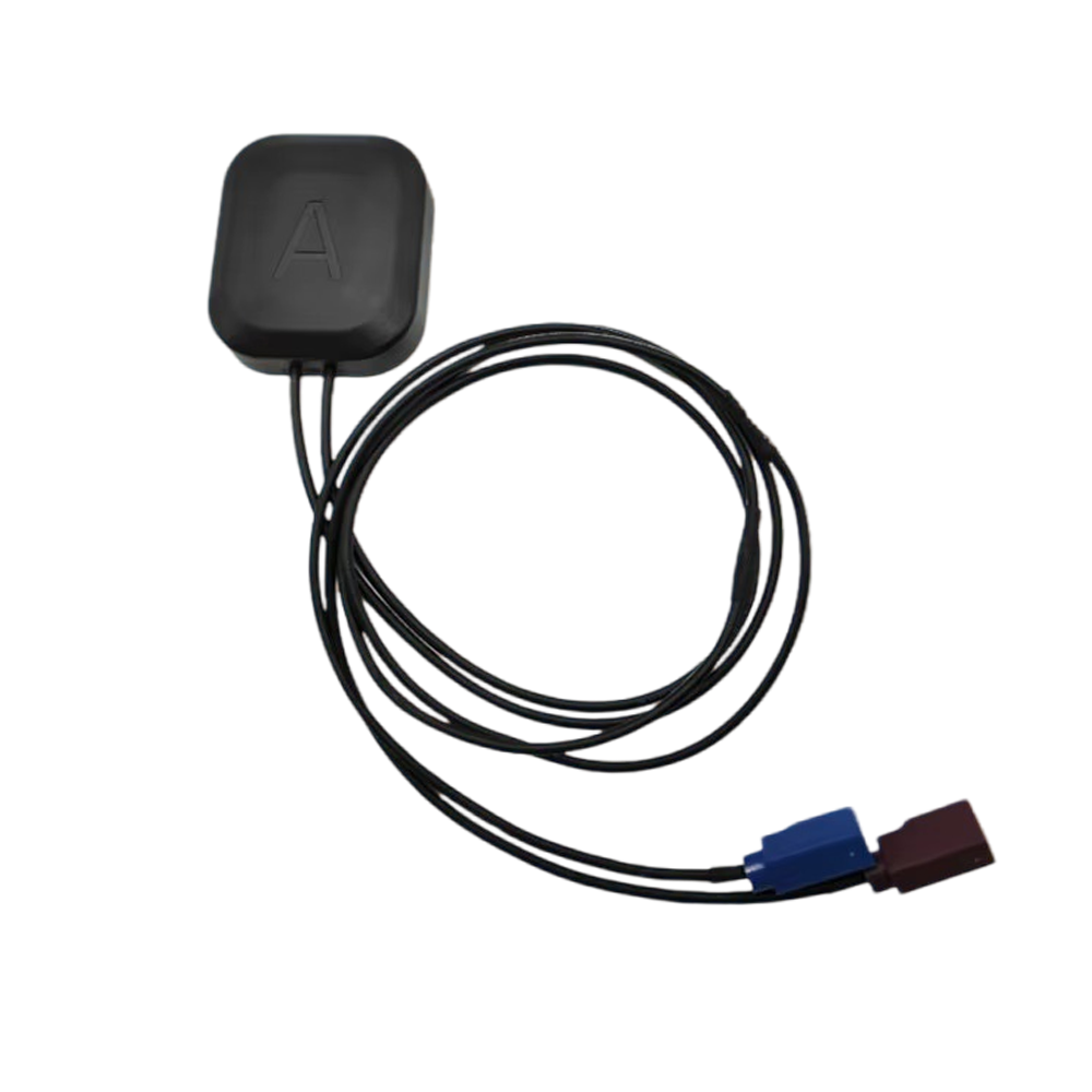

The multi-band FAKRA connector GNSS antenna represents a critical advancement in satellite navigation technology, combining multi-constellation signal reception with automotive-grade connectivity to meet the growing demands of modern applications such as autonomous vehicles, precision agriculture, and industrial IoT.
1.1. Evolution of GNSS Antennas
Traditional GNSS antennas were limited to single-frequency bands (e.g., GPS L1 at 1575.42 MHz), offering basic positioning accuracy. However, with the expansion of global navigation systems—including GPS (USA), GLONASS (Russia), Galileo (EU), BeiDou (China), and QZSS (Japan)—the need for multi-band antennas capable of receiving signals across multiple frequencies (L1/L2/L5, E1/E5, B1/B2/B3) has become essential.
Multi-band antennas improve positioning accuracy by mitigating ionospheric delays, multipath errors, and signal obstructions, enabling sub-meter to centimeter-level precision when combined with Real-Time Kinematic (RTK) or Precise Point Positioning (PPP) techniques.
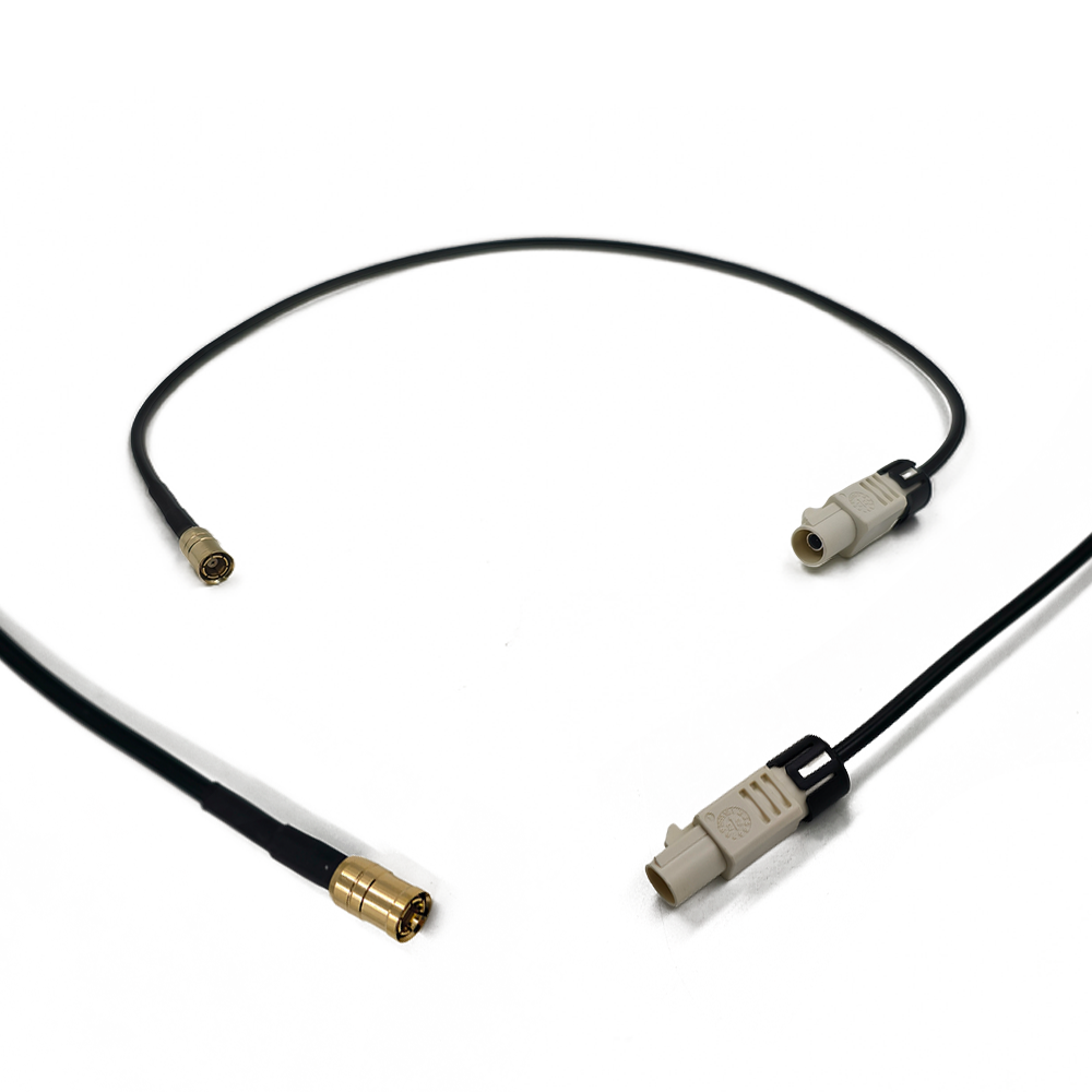
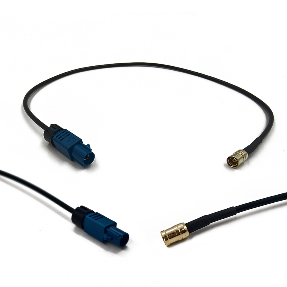
1.2. Role of FAKRA Connectors in GNSS Systems
The FAKRA (Fachkreis Automobil) connector, standardized by DIN 72594-1, is a high-frequency coaxial interface widely used in automotive electronics due to its secure locking mechanism, vibration resistance, and color-coded identification.
Key advantages of FAKRA connectors in GNSS applications:
Robust mechanical design prevents disconnection due to vibrations.
Standardized impedance (50 Ω) ensures minimal signal loss.
Color-coding and keying simplify installation and prevent mismating.
Compatibility with automotive-grade cables (e.g., RG174, RG58) for long-distance signal transmission.
1.3. Market Drivers and Industry Trends
The global market for multi-band GNSS antennas is projected to grow at a CAGR of 12.5% (2023–2030), driven by:
Autonomous vehicles requiring high-precision navigation.
Smart farming (precision agriculture) for yield optimization.
Industrial automation (drones, robotics, AGVs).
Government mandates for E911 emergency positioning in mobile devices.
Leading manufacturers such as u-blox, Taoglas, and Harada are integrating multi-band GNSS receivers with FAKRA-compliant antennas to meet these demands.
A multi-band FAKRA GNSS antenna operates by receiving, filtering, and amplifying satellite signals before transmitting them to a GNSS receiver via the FAKRA connector.
3.1. Signal Reception Mechanism
Satellite signals (right-hand circular polarization, RHCP) impinge on the antenna.
The radiating element resonates at multiple frequencies (L1, L2, L5, etc.).
Induced currents are converted to voltage signals.
3.2. Multi-Band Filtering
A Surface Acoustic Wave (SAW) filter or Band-Pass Filter (BPF) isolates the desired GNSS bands while rejecting out-of-band interference (e.g., LTE, Wi-Fi).
3.3. Low-Noise Amplification (LNA)
An integrated LNA boosts weak satellite signals (typically -130 dBm to -160 dBm) while maintaining a Noise Figure (NF) < 2 dB to prevent signal degradation.
3.4. Signal Transmission via FAKRA Connector
The amplified signal travels through a 50 Ω coaxial cable connected to the FAKRA plug, ensuring lossless transmission to the GNSS receiver.
The operation of a high-precision FAKRA GNSS antenna is a symphony of physics and engineering, translating faint electromagnetic waves from space into a precise digital location. Understanding its working principles requires moving beyond simple reception to appreciate how its design enables the complex algorithms in the receiver to achieve unparalleled accuracy.
Fundamental Signal Reception
The process begins with GNSS satellites, each transmitting spread-spectrum microwave signals on specific L-band frequencies. By the time these signals travel over 20,000 km to reach the Earth's surface, their power is astonishingly low, often described as being "below the noise floor." The primary job of the antenna is to act as a "collector" for this energy. Its physical aperture and efficient design provide gain, effectively amplifying the desired signals from specific directions (the sky) relative to the omnipresent thermal noise.
The Criticality of Circular Polarization
GNSS signals are transmitted using Right-Hand Circular Polarization (RHCP). A high-precision antenna is specifically designed to be sensitive only to RHCP waves. This offers a significant advantage: signals that reflect off surfaces (like the ground or buildings) undergo a polarization shift, typically becoming Left-Hand Circular Polarized (LHCP). The antenna is inherently less receptive to these reflected LHCP signals. This property is the first and most crucial line of defense against multipath error—a phenomenon where the receiver confuses a delayed reflected signal for a direct one, leading to large positioning errors.
Bandwidth and Multi-Frequency Operation
A standard antenna might only be tuned for the primary L1 frequency (1575.42 MHz). A high-precision antenna, however, is a wideband or multi-resonant device. It must simultaneously and efficiently receive signals on L1, L2 (1227.60 MHz), and L5 (1176.45 MHz) with consistent performance. This capability is non-negotiable for high-precision positioning. The receiver uses the slight delay between these different frequencies to calculate and correct for the ionospheric delay—the slowing of the signal as it passes through the charged particles of the ionosphere, which is the largest source of error in standard GNSS.
Phase Center Stability: The Cornerstone of Precision
The ultimate goal of systems like Real-Time Kinematic (RTK) is to measure the carrier phase of the signal, not just the code. The wavelength of the GPS L1 carrier signal is only about 19 cm. By measuring the phase of this carrier wave to a fraction of a wavelength, centimeter-level accuracy becomes possible.
The antenna's Phase Center is the virtual point from which this signal appears to originate. For these phase measurements to be valid, the phase center must not move. If it shifts when the satellite moves across the sky (azimuth and elevation) or when the temperature changes, it introduces a measurement error that mimics a physical movement of the antenna.
High-precision antennas are meticulously designed to have an extremely stable and well-defined phase center across all angles, frequencies, and temperatures. Manufacturers provide detailed calibration tables (ANTEX files) that map the precise phase center variations (PCV) for their antennas. The receiver uses these tables to correct the raw measurements, eliminating this source of error before the positioning calculation even begins.
The Role of the Ground Plane and Radiation Pattern
The antenna's radiation pattern is sculpted to maximize gain towards the horizon and slightly above it (where most satellites are located) and to minimize gain (nulls) towards the ground. This high front-to-back ratio further suppresses multipath signals arriving from below the antenna. The ground plane is essential in creating this pattern. In a vehicle-mounted antenna, the car's metal roof becomes an integral part of this system, and the antenna is designed with this in mind.
The Path to the Receiver
Once the antenna has captured the signals, its task is to deliver them to the GNSS receiver with minimal loss and distortion. This is where the coaxial cable and the FAKRA connector play their part.
The low-loss coaxial cable is chosen to preserve the weak signal strength. Longer cables have more loss, which degrades the signal-to-noise ratio (SNR), so a balance must be struck between installation flexibility and performance.
The FAKRA connector ensures a perfect 50-ohm impedance match at the interface. Any impedance mismatch causes a portion of the signal to be reflected back towards the antenna (measured as VSWR), reducing power transfer and potentially distorting the signal. The FAKRA standard guarantees a consistent, high-quality connection that maintains the integrity of the signal chain.
In essence, the working principle of a high-precision antenna is not passive; it is an active and critical participant in the measurement process. It doesn't just "hear" the satellites; it carefully curates the signals, rejecting noise and multipath, presenting a clean, stable, and multi-frequency set of data to the receiver. It provides the high-quality "raw material"—the carrier phase measurements—that the receiver's sophisticated algorithms then use to resolve integer ambiguities and compute a position with centimeter-level certainty. The antenna's stability and predictability are what make this complex mathematical process possible.
4.1. Key Advantages
✅ High Precision: Multi-band reception enables RTK/PPP positioning with <10 cm accuracy.
✅ Global Compatibility: Supports GPS, GLONASS, Galileo, BeiDou, and QZSS.
✅ Automotive-Grade Reliability: FAKRA connectors withstand vibrations and temperature extremes.
✅ Compact Form Factor: Suitable for space-constrained applications (drones, dashcams).
4.2. Technical Challenges
❌ Signal Interference: Adjacent-channel interference (ACI) from cellular networks (e.g., LTE Band 13) requires advanced filtering.
❌ Thermal Management: LNAs generate heat, necessitating thermal pads or heatsinks in high-temperature environments.
❌ Cost: Multi-band antennas with FAKRA connectors are 2–3x more expensive than single-band alternatives.
5.1. Current Applications
� Autonomous Vehicles: High-definition mapping and lane-level navigation.
� Precision Agriculture: Autonomous tractors and crop monitoring.
�️ Construction & Surveying: Machine control and 3D modeling.
� Unmanned Aerial Vehicles (UAVs): Geotagging and obstacle avoidance.
5.2. Future Trends
� Integration with 5G & V2X: Combining GNSS with vehicle-to-everything (V2X) communication for enhanced safety.
� AI-Enhanced Positioning: Machine learning algorithms to mitigate multipath errors.
� Miniaturization: Chip-scale antennas for smartphones and wearables.
6. Conclusion
The multi-band FAKRA connector GNSS antenna is a transformative technology enabling high-precision navigation across automotive, industrial, and consumer applications. Despite challenges like cost and interference, advancements in filtering, thermal management, and miniaturization will drive widespread adoption in the autonomous era.

 86 0755 2819 9597
Lucy Yang | lucy.y@toxutech.com
Nicole Li | nicole@toxutech.com
Dotty Zhao | sales04@toxutech.com
Global Business Director / Sales Team / Global Operations


 En
En Cn
Cn Korean
 Home >


