

-
Products -PCBA Manufacturing RF Connectors RF Cable Assemblys Embedded Antennas External Antennas Positioning Chips and Modules
RF Connectors

RF Cable Assemblys
Embedded Antennas
External Antennas
Positioning Chips and Modules


 Language


Language


In the intricate ecosystem of global navigation and wireless communication, the antenna serves as the fundamental transducer, the critical interface between the ethereal realm of electromagnetic waves and the concrete world of electronic signals. Among the diverse array of antenna technologies, the miniature passive GNSS ceramic antenna represents a pinnacle of specialized miniaturization, a component engineered to address the unique and demanding challenge of receiving ultra-weak signals from a constellation of satellites orbiting over 20,000 kilometers above the Earth. This device is not a generic receiver; it is a highly optimized solution, balancing the conflicting priorities of physical size, electrical performance, cost, and manufacturability to enable location awareness in a generation of increasingly compact and portable devices.
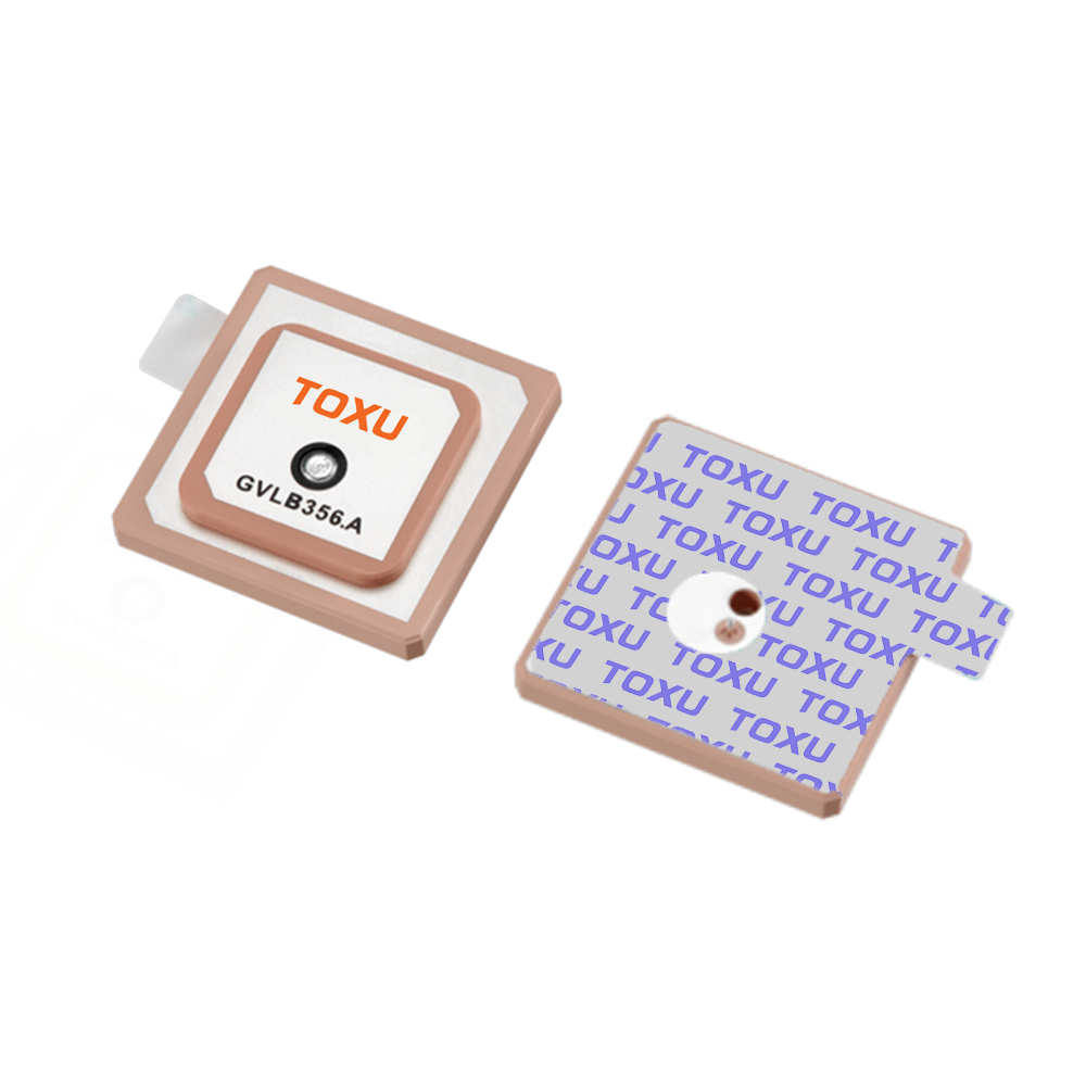
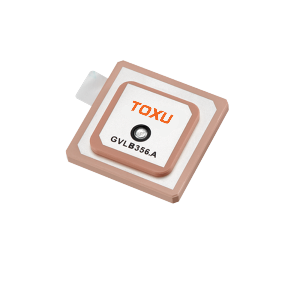
A miniature passive GNSS ceramic antenna is a type of microstrip patch antenna, a design favored for its low profile and planar structure. The term "miniature" typically encompasses footprints ranging from as small as 5x5mm up to the common industry standard of 15x15mm or 18x18mm. "Passive" denotes that the antenna itself contains no active electronic components for amplification; it is a purely resonant structure that relies on the receiver's integrated low-noise amplifier (LNA) to boost the captured signal. This contrasts with "active" antennas, which incorporate an LNA, offering superior performance but at a higher cost, complexity, and power requirement. The most critical element is the "ceramic" substrate, a specialized material with a high dielectric constant (εr) that is the key to the antenna's compact dimensions.
The core function of this antenna is to receive Right-Hand Circularly Polarized (RHCP) signals transmitted across multiple frequency bands by various Global Navigation Satellite Systems (GNSS), including GPS (USA), GLONASS (Russia), Galileo (EU), and BeiDou (China). The primary bands are L1 ( centered around 1575.42 MHz), L2 (1227.60 MHz), L5 (1176.45 MHz), and others. These signals are incredibly faint, with received power levels often below -130 dBm, comparable to viewing a 25-watt light bulb from over 10,000 miles away. The antenna's role is to resonate at these target frequencies, efficiently capture this minute energy, and transfer it via an impedance-matched transmission line to the input of a GNSS receiver module or chip.
The driving force behind the development of these miniature antennas is the explosive growth of the consumer electronics and Internet of Things (IoT) markets. As GNSS functionality evolved from a specialized tool for surveyors and mariners into a standard feature for smartphones, wearables, drones, asset trackers, and automotive telematics, the demand for antennas that were small, cheap, reliable, and easy to integrate skyrocketed. The ceramic patch antenna emerged as the ideal candidate. Its surface-mount technology (SMT) compatibility allows for fully automated pick-and-place assembly, drastically reducing manufacturing costs. Its rigid structure provides robustness against vibration and physical shock, and its performance, while a compromise compared to larger antennas, is entirely adequate for the meter-level accuracy required by most consumer applications.
The high dielectric constant of the ceramic substrate (typically between 20 and 40) is the fundamental enabler of its small size. The physical dimensions of an antenna are inversely proportional to the square root of the dielectric constant (λ_d = λ_0 / √εr, where λ_0 is the free-space wavelength). For the GPS L1 frequency (λ_0 ≈ 19 cm), a standard dielectric material like FR4 (εr ≈ 4.3) would require a patch length of nearly 70mm. By using a ceramic with εr = 36, this dimension is reduced by a factor of 3, allowing for a resonant patch to fit on a component smaller than 15mm per side.
In essence, the miniature passive GNSS ceramic antenna is a masterpiece of engineering compromise. It willingly sacrifices the raw performance, bandwidth, and gain of larger, active, or geodetic-grade antennas to achieve the miniaturization, cost-effectiveness, and ruggedness demanded by high-volume mass production. It is the unsung hero of the location revolution, a tiny, silent sentinel that listens to the whispers from space, enabling everything from turn-by-turn navigation on a smartphone to tracking a package across the globe.
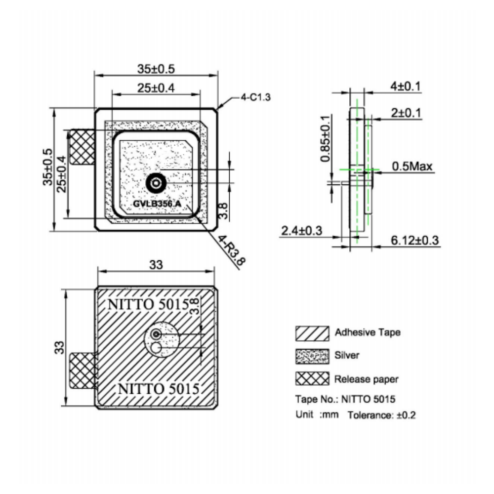
The design and construction of a miniature passive GNSS ceramic antenna is a meticulous process that blends materials science, electromagnetic theory, and precision manufacturing. It is a multi-layered structure where every dimension, material property, and geometric feature is carefully optimized to achieve target performance within a severely constrained physical volume.
1. The Ceramic Substrate: The Engine of Miniaturization
The heart of the antenna is the ceramic block itself. This is not a simple clay but a proprietary, engineered material, often based on titanium ceramics or other complex oxides, sintered under high temperature and pressure to achieve specific electromagnetic properties.
Dielectric Constant (εr): This is the most critical parameter. Values typically range from 20 to over 40. A higher εr allows for a smaller antenna but introduces trade-offs: it reduces bandwidth and can increase dielectric losses if the material quality is poor. The selection is a balance between the desired miniaturization and acceptable performance.
Loss Tangent (tan δ): This measures the rate at which the dielectric material absorbs and dissipates RF energy as heat. A low loss tangent (e.g., < 0.002) is paramount for achieving high radiation efficiency. Premium ceramics are formulated to minimize this loss, ensuring that captured energy is radiated, not wasted.
Temperature Stability: The dielectric constant of all materials drifts with temperature. For a GNSS antenna, this thermal drift can shift the resonant frequency, potentially moving it outside the desired band. High-quality ceramic blends are engineered to have a stable εr across a wide operating temperature range (e.g., -40°C to +85°C) to ensure consistent performance in any environment.
2. The Radiating Element: The Patch
On the top surface of the ceramic block, a conductive radiating patch is deposited. This is typically achieved by screen-printing a silver-based conductive ink onto the raw ceramic, which is then co-fired in a kiln, fusing the metal to the substrate to create a durable, low-resistance layer.
Patch Geometry: The patch is most commonly square or rectangular, as these geometries support the resonant Transverse Magnetic (TM) modes required for operation. Its precise dimensions are calculated to be slightly less than half the wavelength within the dielectric material (λ_d/2) at the target center frequency.
Multi-Band Designs: To cover multiple GNSS bands (e.g., L1 and L2/L5), more complex designs are employed. The most common method is the stacked patch, where a second, larger parasitic patch is printed on a separate ceramic layer and placed above the primary driven patch. The lower patch is tuned to the higher frequency (L1), and the upper patch is coupled to it and resonant at the lower frequency (L2/L5). Other techniques include slotting the patch or using multi-feed points.
3. Achieving Circular Polarization
GNSS signals use Right-Hand Circular Polarization (RHCP) to mitigate signal degradation caused by atmospheric effects and to provide a measure of discrimination against reflected signals. A simple patch is linearly polarized. To achieve CP, the antenna must radiate two orthogonal field components of equal amplitude with a 90-degree phase difference.
Single-Feed Techniques (e.g., Truncated Corners): The simplest and most cost-effective method is to disrupt the symmetry of a square patch. Truncating two opposite corners perturbs the surface current paths, splitting the single resonant mode into two orthogonal modes with the required phase shift. The size of the truncation is critical for achieving a good Axial Ratio (AR), a measure of the purity of the circular polarization.
Dual-Feed Techniques: A higher-performance method involves feeding the patch at two orthogonal points using a 90-degree hybrid coupler. This ensures perfect amplitude and phase balance, resulting in excellent AR across a wider angular range. However, this approach is more complex, requires more space, and is less common in mass-produced miniature antennas due to cost and size constraints.
4. The Ground Plane and Feed Point
The entire bottom surface of the ceramic block is metallized to form a solid ground plane. This ground plane is essential for the antenna's operation: it creates a directional radiation pattern (maximizing gain towards the sky), provides shielding from noise generated by the underlying PCB, and serves as the electrical reference for the radiating patch.
The antenna is connected to the circuit via a feed point, typically a soldering pad on the side or bottom of the component. The location of this feed point is crucial for achieving a good impedance match to the system's characteristic impedance (50 ohms).
5. Integration with the Host PCB: The Co-Design Imperative
A passive ceramic antenna does not operate in isolation. Its performance is inextricably linked to the printed circuit board (PCB) on which it is mounted. The host PCB becomes an integral part of the antenna system.
The Keep-Out Area: The single most important rule is the mandatory keep-out area. The ground plane on the host PCB must be completely removed from the region directly beneath and immediately surrounding the antenna. The presence of copper or components in this area will capacitively load the antenna, detuning its resonant frequency and severely degrading its performance.
The PCB as a Counterpoise: While the area directly under the antenna is clear, the rest of the PCB's ground plane is vital. It acts as a counterpoise, providing a reference for the antenna's currents. The size and shape of this PCB ground can significantly influence the antenna's bandwidth and radiation pattern.
Matching Network: Even with a perfect design, the antenna's impedance may not be exactly 50 ohms. Therefore, a simple passive matching network (typically a Pi- or T-network of capacitors and inductors) is placed on the PCB between the receiver chip and the antenna feed point. This network fine-tunes the impedance to ensure maximum power transfer, effectively "locking" the antenna to the desired frequency band.
The construction process concludes with rigorous testing. Samples from each production batch are measured in test fixtures to verify key parameters: return loss (S11), resonant frequency, bandwidth, radiation pattern, and axial ratio. This ensures that the component meets its datasheet specifications before being shipped to customers who will integrate it into the next generation of location-aware devices.
The operation of a miniature passive GNSS ceramic antenna is a practical demonstration of resonant electromagnetic theory, tailored for extreme miniaturization. Its working principle can be deconstructed into its function as a resonant cavity, its mechanism for achieving circular polarization, the formation of its radiation pattern, and its critical interplay with the host circuit.
Fundamental Resonance: The Cavity Model
The antenna operates fundamentally as a resonant cavity. The top metallized patch and the bottom ground plane form the two conducting walls, and the high-dielectric ceramic between them acts as the cavity filling. The length L of the patch is designed to be approximately half the wavelength within the dielectric material (λ_d / 2) at the target frequency (e.g., 1575.42 MHz for L1). When excited by an RF signal at this frequency, a standing wave is established between the radiating edges of the patch. The dominant mode of operation is the TM₁₀ mode, where the electric field is vertical (perpendicular to the patch) and its magnitude varies sinusoidally across the length of the patch, reaching a maximum at the center and falling to zero at the edges. The "fringing fields" at these edges bulge out from the cavity and are responsible for coupling energy into free space, enabling radiation.
The Mechanism of Circular Polarization
A key requirement for efficient GNSS reception is sensitivity to Right-Hand Circular Polarization (RHCP). A perfectly square patch fed at one point produces linear polarization, where the electric field vector oscillates in a single plane. This is inefficient for receiving a circularly polarized signal, incurring a constant 3 dB loss.
To create CP, the antenna must generate two orthogonal electric field components of equal amplitude but with a 90-degree phase difference. In the common truncated-corner design, the physical asymmetry introduced by cutting off two opposite corners disrupts the surface current flow. This perturbation splits the antenna's natural resonant frequency into two closely spaced resonant frequencies. Each frequency is associated with a different current mode, and these two modes are orthogonal in space. Due to the nature of the perturbation, these modes are excited with a 90-degree phase shift. The superposition of these two fields results in a wave whose electric field vector rotates in a circle, creating either RHCP or LHCP, depending on which corners are truncated. The design is meticulously optimized to ensure this rotation is right-handed.
Radiation Pattern and the Role of the Ground Plane
The presence of the ground plane is fundamental to shaping the antenna's performance. Using image theory, the ground plane can be thought of as creating a mirror image of the antenna below it. This results in a radiation pattern that is directional, with most of the energy being radiated in a broad hemisphere above the board. The pattern is not uniform; it typically exhibits maximum gain at broadside (perpendicular to the patch surface) and reduced gain at lower elevation angles towards the horizon. This is actually beneficial for GNSS applications, as satellites are never below the antenna and are most prevalent at elevations between 15 and 70 degrees. The ground plane also provides inherent, though limited, rejection of multipath signals, which often arrive at very low elevation angles after reflecting off the ground or other objects.
Impedance Matching and Bandwidth
For maximum power transfer, the impedance at the antenna's feed point must be matched to the impedance of the transmission line feeding it (standardized at 50 ohms). The impedance is highly sensitive to the feed point's location. Feeding along the centerline provides a good match for a linear patch. For circularly polarized designs, the feed is typically placed along the diagonal, offset from the center, to excite the two orthogonal modes equally.
The "passive" and "miniature" nature of the antenna dictates its most significant limitation: narrow bandwidth. The high dielectric constant required for small size inherently reduces bandwidth. Furthermore, the small physical volume of the antenna limits its energy storage capacity, which directly correlates to bandwidth. A typical miniature ceramic antenna might have a -10 dB bandwidth of only 20-30 MHz, which is just sufficient to cover a single GNSS band like L1 but is inadequate to cover multiple widely spaced bands (e.g., L1 and L5) without advanced design techniques like stacking.
The Complete Signal Path and System Integration
Capture: Faint RHCP waves from GNSS satellites induce tiny, oscillating currents on the radiating patch.
Resonance: The patch resonates, selectively amplifying signals in the GNSS band while rejecting others.
Polarization Conversion: The truncated corners or other features convert the captured energy into two phased components, effectively receiving the RHCP signal.
Transfer: The energy is coupled from the patch through the feed point.
Matching: The external Pi-network matching circuit on the host PCB fine-tunes the impedance for maximum power transfer to the 50-ohm transmission line.
Transmission: The incredibly weak signal (often below -130 dBm) travels along a microstrip trace to the input pin of the GNSS receiver module.
Amplification: The receiver's integrated Low-Noise Amplifier (LNA) performs the first critical stage of amplification, boosting the signal for downstream processing and digitization.
It is crucial to understand that the antenna's performance is not intrinsic to the component alone. Its resonance, bandwidth, and efficiency are co-determined by its integration environment. The size of the PCB's ground plane, the adherence to the keep-out area, and the proximity of other components and the device's housing can all dramatically detune the antenna. Therefore, its working principle is a partnership between the component manufacturer and the product design engineer.
The miniature passive GNSS ceramic antenna is a study in engineering trade-offs. Its widespread adoption is driven by a compelling set of advantages that align perfectly with the needs of modern consumer electronics. However, these advantages are counterbalanced by a distinct set of challenges that must be carefully managed during the product design process to avoid catastrophic performance failure.
Advantages
Exceptional Miniaturization and Low Profile: This is the paramount advantage. Footprints as small as 5x5mm allow integration into incredibly space-constrained devices like smartwatches, compact IoT sensors, and wearable medical devices. Their height is also minimal, often around 4mm, making them ideal for ultra-slim smartphones and tablets.
Low Unit Cost and High-Volume manufacturability: The manufacturing process, based on ceramic sintering and screen printing, is highly automated and scalable. This enables production volumes in the millions of units at a phenomenally low per-unit cost, often just a few dollars or even cents. This economics is essential for cost-sensitive consumer goods.
Robustness and Mechanical Reliability: The monolithic ceramic structure is inherently rigid, resistant to deformation, vibration, and shock. It can withstand the high temperatures of reflow soldering processes without damage. Once soldered to a PCB, it forms a very durable and reliable connection, far more robust than a flexible printed circuit (FPC) antenna or a solder-connected external antenna.
Surface-Mount Technology (SMT) Compatibility: As a standard SMT component, it is perfectly suited for modern automated PCB assembly lines. It can be handled by pick-and-place machines, soldered in a reflow oven alongside resistors and capacitors, and visually inspected, simplifying logistics and assembly and minimizing labor costs.
Adequate Performance for Consumer Applications: For its size, it provides perfectly acceptable performance for the majority of mass-market applications. When integrated correctly, it can deliver the necessary gain pattern to achieve a solid position fix with 3-5 meter accuracy, which is sufficient for navigation, fitness tracking, and basic asset monitoring.
Zero Power Consumption: Being purely passive, it requires no bias voltage or current. This simplifies the design (no need for a bias-T circuit), reduces overall system power budget (critical for battery-operated devices), and eliminates a potential source of electronic noise.
Challenges and Limitations
Inherently Narrow Bandwidth: The high dielectric constant needed for small size is the direct cause of very limited bandwidth. This is the antenna's greatest weakness. It typically confines a single component to a single band (e.g., L1 only). Covering multiple bands (e.g., L1 and L5) requires more complex, larger, and expensive stacked designs, negating the miniaturization advantage.
Extreme Integration Sensitivity: This is the most significant challenge for system designers. The antenna's performance is not guaranteed by the component itself but is a product of its integration.
Keep-Out Area: The requirement for a large, clear keep-out area on the PCB (no ground or components) conflicts with the desire for ever-smaller and more densely packed boards.
Ground Plane Dependence: The antenna's bandwidth and radiation pattern are heavily influenced by the size and shape of the PCB's ground plane. A poorly sized ground can render a high-quality antenna useless.
Environmental Detuning: Proximity to plastics, batteries, displays, and even the user's hand can capacitively load the antenna, shifting its resonant frequency outside the GNSS band and causing a complete loss of signal. This necessitates extensive prototyping and testing in the final product enclosure.
Lower Efficiency and Gain: Due to their small size and dielectric losses, these antennas have lower radiation efficiency compared to larger patches or external antennas. This translates to lower gain, making them more susceptible to signal dropouts in challenging environments like dense urban areas ("urban canyons") or under heavy tree cover.
Limited Multi-Band and Multi-Constellation Capability: A standard single-layer design is typically optimized for one band, usually GPS L1. While it can often receive other constellations on the same band (e.g., Galileo E1), its performance may be sub-optimal. It cannot natively support the modern multi-band signals (L2, L5, E5, E6) that are key to high-accuracy, robust positioning.
Sensitivity to Manufacturing Tolerances: Minor variations in the ceramic's dielectric constant during sintering or slight misalignments in the screen-printing process can cause shifts in the center frequency and impedance. While the external matching network can compensate, it introduces unit-to-unit variability that must be accounted for in the design.
Lack of Signal Amplification: As a passive antenna, it provides no gain. The weak signal it captures is then subject to loss in the transmission line (microstrip trace) on the PCB. Any loss here (e.g., 1-2 dB) directly degrades the system's overall Signal-to-Noise Ratio (SNR), placing a heavier burden on the receiver's LNA to have an exceptionally low noise figure.
In conclusion, the miniature passive ceramic antenna is a tool of compromise. Its immense advantages in size, cost, and manufacturability make it the default choice for a huge range of consumer devices. However, its successful deployment is not trivial. It demands expert RF design, careful PCB layout, and thorough validation to overcome its challenges and realize its potential, ensuring that this tiny window to the satellites performs as intended.
The miniature passive GNSS ceramic antenna is a foundational enabling technology for the modern location-aware world. Its specific combination of attributes has made it the cornerstone of entire product categories within consumer electronics and the Internet of Things (IoT). As technology evolves, its role is simultaneously being cemented in certain domains and challenged in others, leading to interesting future trends.
Applications
Smartphones and Personal Electronics: This remains the largest application volume driver. While flagship smartphones often use more integrated antenna designs (like LDS on the frame), miniature ceramics are ubiquitous in mid-range and budget devices. They are also found in tablets, personal navigation devices (PNDs), and handheld gaming systems.
Wearable Technology: This is an ideal application. Fitness trackers, smartwatches, and wearable health monitors have extreme space constraints. A 5x5mm or 7x7mm ceramic antenna provides just enough performance for activity tracking, run mapping, and location tagging without significantly impacting the device's form factor or battery life.
Asset Tracking and IoT Logistics: The explosion of IoT is a major growth area. Small, low-cost trackers for monitoring shipping containers, pallets, vehicles, and high-value assets rely on these antennas to report their position periodically. Their low cost is critical for large-scale deployments, and their robustness ensures survival in harsh logistics environments.
Drones and Unmanned Aerial Vehicles (UAVs): Consumer drones and small professional UAVs use these antennas for basic navigation, position holding, and return-to-home functions. Their minimal size and weight are paramount in aviation design, where every gram affects flight time.
Automotive Telematics and Aftermarket Devices: Beyond in-dash infotainment systems, these antennas are found in usage-based insurance (UBI) dongles, fleet management trackers, and aftermarket security systems. Their SMT format allows for compact and discreet module design.
Consumer Gadgets and Cameras: Digital cameras and action cams use them for geotagging photos. Pet trackers and personal safety devices use them to report location. Even some laptops embed them for location services.
Future Trends
The future of this technology is not about replacement but about evolution and specialization within a broader ecosystem of positioning technologies.
Niche Specialization and Market Consolidation: The trend towards integrated antenna solutions (e.g., LDS, ceramic patch antennas embedded into modules) will continue in high-end devices. The standalone miniature ceramic antenna will increasingly become the solution of choice for specific, high-volume niches: ultra-compact wearables, cost-optimized IoT sensors, and devices where its simplicity and reliability are valued over integration complexity.
The Push for Multi-Band Capability in Small Form Factors: The adoption of multi-band GNSS (L1+L5, L1+L2) for better accuracy and robustness is the biggest technical challenge. This will drive innovation in multi-layer stacked ceramic technology to fit dual-band functionality into a minimally larger footprint (e.g., 15x15mm). Advances in 3D electromagnetic simulation are key to optimizing these complex designs.
Enhanced Integration and "Antenna-in-Package": A significant trend is the move towards System-in-Package (SiP) and Antenna-in-Package (AiP) solutions. Here, the ceramic antenna is no longer a discrete component on the main PCB but is co-packaged with the GNSS receiver chip and other RF components into a single, pre-tested module. This simplifies design for the end customer but moves the integration challenge to the module manufacturer.
Material Science Innovations: Research into new ceramic and composite materials continues. Goals include developing dielectrics with a more stable temperature coefficient, a better balance between high εr and low loss tangent, and even tunable materials that could allow for slight frequency adjustments post-manufacturing.
Co-Design with AI and Simulation: The use of sophisticated 3D EM simulation software (ANSYS HFSS, CST) is already standard. The future involves using machine learning and AI algorithms to rapidly iterate through thousands of potential design variations (patch shape, feed location, ceramic properties) to automatically optimize for specific goals like bandwidth, efficiency, or size, dramatically accelerating the design process.
Resilience in Noisy Environments: As the RF spectrum becomes more crowded, there is a growing need for antennas with better inherent rejection of out-of-band interference. Future designs may incorporate embedded filtering structures within the ceramic stack or more advanced grounding techniques to improve resilience without adding external components.
The miniature passive GNSS ceramic antenna is not becoming obsolete; it is maturing. Its future lies in being a highly optimized, ultra-reliable, and incredibly cost-effective solution for the vast "good enough" segment of the market. It will continue to be the workhorse that provides basic location functionality to billions of devices, even as more advanced and integrated solutions emerge for high-performance applications.
Conclusion
The miniature passive GNSS ceramic antenna is a paradigm of targeted engineering excellence. It stands as a powerful testament to the principle that optimal design is not about achieving absolute peak performance in a vacuum, but about mastering the intricate trade-offs required to meet a specific set of market-driven constraints. In this case, the constraints are severe: minimal physical size, ultra-low cost, high-volume manufacturability, and unwavering reliability. In meeting these challenges, this antenna has become an indispensable enabler of the modern, connected world.
Its design is an elegant solution to a fundamental physics problem. The use of a high-dielectric-constant ceramic substrate is the masterstroke that allows it to defy conventional antenna scaling laws, resonating at satellite frequencies within a volume smaller than a fingertip. Techniques like corner truncation provide a clever and economical path to achieving the necessary circular polarization, a feature critical for effective satellite signal reception.
The analysis of its advantages and limitations paints a clear picture of its identity. It is a component of compromise. Its unparalleled miniaturization and cost-effectiveness are counterbalanced by its narrow bandwidth, integration sensitivity, and performance that is merely "adequate" rather than exceptional. It is a component that demands respect and expertise; its successful implementation is a reward earned through meticulous PCB layout, strict adherence to keep-out rules, and comprehensive testing within the final product ecosystem. It fails silently and absolutely if ignored or treated as a simple commodity.
Its applications are a veritable map of the digital age, from the watch on your wrist to the tracker on a cargo ship. It has democratized access to global positioning, transforming it from a specialist's tool into a ubiquitous utility. As technology progresses, its role will evolve. It will likely cede ground in high-performance applications to more integrated and multi-band solutions while simultaneously solidifying its dominance in the high-volume, cost-sensitive world of compact IoT and consumer devices.
In the grand narrative of wireless technology, the miniature passive GNSS ceramic antenna may not be the glamorous hero achieving centimeter-level accuracy. Instead, it is the reliable, unsung workhorse that delivers fundamental location capability to the masses. It demonstrates that profound impact often comes not from pushing the boundaries of what is possible in a lab, but from perfecting the art of the feasible for the factory floor. It is a masterpiece of focused engineering—a tiny, silent, and remarkably sophisticated ceramic tile that has helped the world find its way.

 86 0755 2819 9597
Lucy Yang | lucy.y@toxutech.com
Nicole Li | nicole@toxutech.com
Dotty Zhao | sales04@toxutech.com
Global Business Director / Sales Team / Global Operations


 En
En Cn
Cn Korean
 Home >


