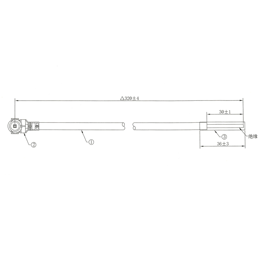
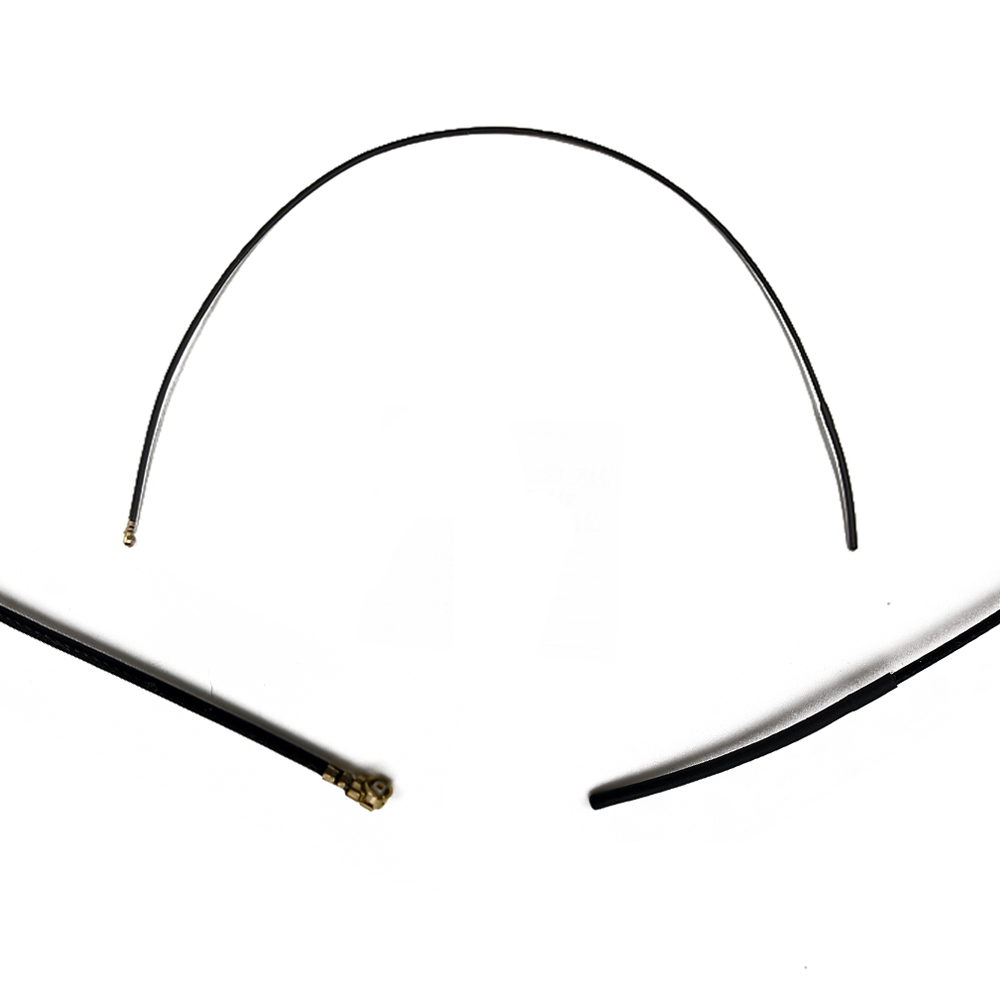
The Global Navigation Satellite System (GNSS) has evolved from a specialized military technology into an indispensable utility underpinning modern civilization. From guiding aircraft and orchestrating global shipping logistics to enabling turn-by-turn directions on a smartphone, GNSS precision is a cornerstone of contemporary life. At the heart of every GNSS receiver lies its most critical and often most misunderstood component: the antenna. The miniature compact GNSS antenna represents the pinnacle of the miniaturization and performance optimization of this essential technology. This overview delves into the fundamental role, key characteristics, and evolving significance of these tiny yet powerful devices.
In its simplest definition, a GNSS antenna is a transducer designed to convert the electromagnetic waves broadcast by navigation satellites into an electrical current that can be processed by a receiver. A miniature compact GNSS antenna performs this function within an exceptionally small form factor, typically measuring from a few millimeters to a few centimeters in its largest dimension. This radical miniaturization is not merely an aesthetic or convenience-driven endeavor; it is an engineering response to the explosive growth of small, portable, and ubiquitous electronics. The drive towards the Internet of Things (IoT), wearable technology, unmanned aerial vehicles (UAVs), precision agriculture, and advanced automotive telematics has created a pressing need for highly accurate positioning capabilities in devices where space is at an absolute premium.
The core function of any GNSS antenna is to capture the incredibly weak right-hand circularly polarized (RHCP) signals transmitted from satellites orbiting over 20,000 kilometers above the Earth. These signals are astonishingly feeble by the time they reach the Earth's surface, thermal noise and a plethora of terrestrial radio frequency (RF) interference. Therefore, the primary mandate of a GNSS antenna is not just to receive these signals but to amplify them significantly while rejecting as much noise and interference as possible. Key performance parameters include gain, which measures amplification; bandwidth, which defines the range of frequencies it can receive (covering constellations like GPS, GLONASS, Galileo, and BeiDou); phase center stability, which is critical for high precision; and axial ratio, which defines its efficiency at receiving circularly polarized waves.
The journey of GNSS antenna technology has been one of relentless innovation. Early antennas were relatively large, passive, and often cumbersome, suitable for marine vessels or survey equipment but not for consumer gadgets. The development of the patch antenna, particularly the microstrip patch antenna, was a revolutionary step. This design, essentially a metallic patch on a grounded dielectric substrate, offered a low-profile, manufacturable, and robust solution. Further advancements in materials science, ceramic dielectric substrates, and sophisticated simulation software have enabled engineers to shrink these patches while enhancing their performance through techniques like multi-feed points for phase center stability and sophisticated grounding planes to manage size constraints.
The miniaturization paradigm introduces a fundamental electromagnetic trade-off: antenna efficiency is intrinsically linked to its physical size relative to the wavelength of the signal it is designed to receive. The GNSS L-band operates at wavelengths around 19-25 cm (frequencies from 1.1 to 1.6 GHz). A perfect, isotropic antenna at these frequencies would be impractically large for most modern applications. Therefore, miniature antennas are inherently compromise solutions. Engineers employ clever designs, high-permittivity ceramic materials that effectively "slow down" the wave, allowing for a smaller resonant structure, and advanced active circuitry to overcome the inherent efficiency losses. The result is an antenna that, while not as efficient as a large survey-grade antenna, provides more than adequate performance for its intended application within a tiny footprint.
In conclusion, the miniature compact GNSS antenna is a testament to modern RF engineering. It is a critical enabler for a new generation of technology, transforming devices from passive objects into spatially aware intelligent nodes. Its development is a delicate balancing act between the immutable laws of physics and the relentless market demand for smaller, cheaper, and more powerful electronics. As we progress into an era of even greater connectivity and autonomy, the role of these antennas will only become more central, driving innovation in their design, integration, and functionality to meet the challenges of tomorrow's positioning and navigation demands.
The creation of a high-performance miniature compact GNSS antenna is a sophisticated interdisciplinary endeavor, blending electromagnetics, materials science, semiconductor physics, and mechanical engineering. The design process is a continuous negotiation between optimal RF performance and stringent physical constraints. This section explores the architectural choices, material selections, and construction techniques that bring these potent miniature devices to life.
The most prevalent and successful architecture for miniature GNSS antennas is the Ceramic Patch Antenna. This design dominates the market for embedded applications due to its excellent balance of performance, size, cost, and robustness. Its construction is a layered affair:
Ground Plane: The foundation is a conductive ground plane, typically made of copper. This plane serves two vital functions: it acts as a reflector to direct the antenna's radiation pattern upward towards the sky, and it defines the lower frequency limit of the antenna's operation. In miniature designs, the ground plane is often limited in size, which presents a significant design challenge, as a small ground plane can detune the antenna and distort its radiation pattern.
Dielectric Substrate: On top of the ground plane lies a layer of ceramic material with a very high relative permittivity (εr), often between 20 and 40. Materials like lithium tantalate are common. The high permittivity is the key to miniaturization. The wavelength within a material is inversely proportional to the square root of its permittivity (λ = λ₀ / √εr). By using a high-εr ceramic, the effective electrical length of the antenna is increased, allowing the physical patch to be made much smaller while still resonating at the desired L-band frequencies.
Radiating Patch: The top layer is the radiating element itself, a metallic patch (usually silver or copper) etched or printed onto the ceramic surface. The dimensions of this patch—its length, width, and shape—are precisely calculated to determine the resonant frequency and bandwidth.
To achieve multi-constellation support (e.g., GPS L1, GLONASS G1, Galileo E1, BeiDou B1), the antenna must operate over a wide bandwidth (~1550-1610 MHz). A simple square patch has a limited bandwidth. Engineers employ several techniques to enhance it, such as stacking patches, slotting the patch, or using a sophisticated feeding mechanism. A critical advancement is the use of multiple feed points. A single feed point can excite a fundamental resonance. By adding a second feed point at an orthogonal location and feeding it with a signal 90 degrees out of phase, engineers can excite two degenerate modes that combine to produce the desired Right-Hand Circular Polarization (RHCP). This is crucial for rejecting left-hand polarized multipath reflections and aligning with the satellite transmissions.
Beyond the passive ceramic patch, most modern miniature GNSS antennas are Active Antennas. They incorporate a Low-Noise Amplifier (LNA) directly into the antenna assembly or its immediate vicinity. This is a strategic necessity. The satellite signals are exceptionally weak, and the loss introduced by the coaxial cable connecting the antenna to the receiver (especially if it's long) would devastate the signal-to-noise ratio (SNR). By placing an LNA with high gain (e.g., 25-30 dB) and very low noise figure (<1 dB) right at the antenna, the signal is amplified to a robust level before any cable loss occurs. This active component requires power, which is typically supplied to the antenna assembly through the same coaxial cable via a DC bias voltage, a system known as ** Bias-Tee**.
The physical construction must also account for the operating environment. For consumer devices, antennas are often embedded within the device's housing, directly onto its printed circuit board (PCB). This introduces a host of challenges: the proximity of other components, the metal battery, and the plastic or glass fiber housing can all detune the antenna's resonant frequency and distort its pattern. To mitigate this, extensive 3D electromagnetic simulation using software like ANSYS HFSS or CST Studio Suite is mandatory. These tools allow engineers to model the entire device and optimize the antenna's placement and design within the virtual environment before costly physical prototypes are built.
Alternative designs to the ceramic patch include Planar Inverted-F Antennas (PIFAs) and chip antennas. PIFAs are common in mobile phones due to their integrability, though they often have narrower bandwidth and poorer axial ratio performance compared to a well-designed ceramic patch. Chip antennas are extremely small surface-mount devices (SMD) but are highly dependent on a very carefully designed PCB ground plane to function correctly, making them less robust to design changes but ideal for ultra-space-constrained applications.
In summary, the design and construction of a miniature GNSS antenna is a complex puzzle. It involves selecting high-permittivity materials to cheat physics, engineering multi-feed patches for wideband circular polarization, integrating sophisticated active electronics for signal integrity, and meticulously simulating the final deployment environment to ensure performance is not compromised. It is a field where every fraction of a dB in performance and every cubic millimeter of volume is fiercely contested.
Understanding the operation of a miniature compact GNSS antenna requires delving into the fundamental principles of electromagnetism and radio wave propagation. Its job is highly specialized: to efficiently capture a specific set of extremely weak, circularly polarized microwave signals from any point in the sky and convert them into a clean electrical signal for the receiver. This process hinges on the concepts of resonance, polarization, and radiation patterns.
The core principle behind any antenna is electromagnetic resonance. An antenna is a structure designed to resonate at a specific frequency, much like a tuning fork resonates with a specific sound frequency. For a patch antenna, the resonant frequency is primarily determined by the physical length (L) of the patch. The fundamental resonance occurs when this length is approximately half of the wavelength within the dielectric material (L ≈ λ_d / 2). As established, the wavelength in the ceramic dielectric (λ_d) is much shorter than in free space (λ₀), given by λ_d = λ₀ / √εr. This is the mathematical secret to miniaturization. When an electromagnetic wave at the resonant frequency impinges on the patch, it induces a strong standing wave of current on the metallic surface. This oscillating current is then siphoned off through the feed point as a guided electrical signal down the transmission line to the LNA and receiver.
A defining characteristic of GNSS signals is their Right-Hand Circular Polarization (RHCP). Polarization describes the orientation of the electric field vector of the radio wave as it propagates. A circularly polarized wave rotates its electric field in a corkscrew pattern. RHCP means the rotation is clockwise when viewed in the direction of propagation. Satellites use RHCP because it is less affected by Faraday rotation when passing through the ionosphere. For the antenna, this means it must be designed to be most sensitive to RHCP waves and, ideally, reject their mirror image, Left-Hand Circular Polarization (LHCP). This is critically important for mitigating multipath interference, a common GNSS error source where a signal reflects off the ground or buildings before reaching the antenna. A reflection typically reverses the handedness of the polarization, turning an RHCP signal into an LHCP one. An antenna with good RHCP performance will naturally attenuate these reflected LHCP signals, thereby improving accuracy.
The mechanism for achieving circular polarization in a patch antenna is elegant. It involves exciting two orthogonal modes (current distributions) on the patch that are 90 degrees out of phase with each other. This is typically done using either:
A Single Feed with Perturbations: Introducing an asymmetric physical feature, like a notch or a corner cut, on the square patch can degenerate the two resonant modes and create the necessary phase shift.
Dual (or Quad) Feed Points: This is the more controlled and higher-performance method. Two separate feed points are located on the patch with a specific geometric relationship (e.g., on adjacent edges). One feed is driven with the signal, and the other is connected through a passive network (like a 90-degree hybrid coupler) or is actively driven with a phase-shifted signal. The two fed signals, equal in amplitude but 90 degrees out of phase, create the rotating electric field vector that characterizes circular polarization.
The radiation pattern of the antenna is a 3D representation of its sensitivity. For a GNSS antenna, the ideal pattern is a wide hemispherical or semi-spherical shape. It must have high gain from the horizon up to the zenith (directly overhead) to see satellites across the entire sky. Gain at low elevations is particularly important for acquiring a lock quickly and maintaining it in challenging environments like urban canyons. The miniature antenna's radiation pattern is heavily influenced by its ground plane. A larger ground plane provides a more stable and symmetric pattern, while a small, finite ground plane can cause pattern distortion and ripples, reducing gain at certain angles. The antenna's phase center is a hypothetical point from which the radiation seems to emanate. For high-precision applications like RTK or PPP, the phase center must be extremely stable across different angles of arrival of the signal. Any movement of this point introduces measurable errors. Advanced patch designs with multiple symmetric feed points are used to create a very stable and virtual phase center.
Finally, the role of the integrated Low-Noise Amplifier (LNA) cannot be overstated. It performs the critical task of overcoming the system's noise figure. The noise figure is a measure of how much noise is added by each component in the signal chain. According to Friis's formula, the noise figure of the entire system is dominated by the noise figure of the first component. By placing an ultra-low-noise amplifier immediately after the antenna element, the system's overall noise figure is minimized. This LNA provides enough gain to make the signal resilient to the subsequent losses in the cable and the noise introduced by the receiver itself. It effectively "lifts" the faint signal out of the noise floor, making it discernible and processable.
In essence, the working principle of a miniature GNSS antenna is a symphony of physics: it resonates at a precise frequency to capture energy, its structure is engineered to match the satellite's polarization and reject noise, its shape forms a pattern to see the entire sky, and its integrated electronics amplify the whisper of a signal to a shout that the receiver can understand.
The proliferation of miniature compact GNSS antennas has been driven by a compelling set of advantages that align perfectly with technological trends. However, their development and deployment are fraught with significant challenges rooted in the fundamental laws of physics. This section provides a balanced analysis of the benefits and obstacles associated with these devices.
Advantages:
Miniaturization and Form Factor: The most obvious advantage is their small size and low profile. This enables integration into a vast array of products where space is critically limited: smartphones, smartwatches, fitness trackers, animal tags, drones, precision asset trackers, and automotive dashboards. This miniaturization is the primary enabler for the ubiquitous location-awareness we experience today.
Low Cost and Mass Production: The dominant ceramic patch antenna design is highly amenable to automated, large-scale manufacturing processes like printing and sintering. This economies of scale drives the unit cost down to just a few dollars or even cents for high-volume orders, making GNSS technology accessible for consumer-grade products.
Robustness and Reliability: Having no moving parts and being constructed from solid ceramic and printed metals, these antennas are extremely robust. They are resistant to vibration, shock, corrosion, and can be potted or encapsulated to withstand harsh environmental conditions like rain, humidity, and extreme temperatures. This makes them suitable for automotive, aerospace, and industrial applications.
Ease of Integration: Modern active ceramic patch antennas are often supplied as complete modules, pre-tuned and matched to 50 ohms. For a system designer, this simplifies the integration process significantly. It often becomes a matter of providing a clear view of the sky, supplying DC power over the cable, and routing the output to the GNSS receiver IC, reducing the need for deep RF expertise on the product design team.
Multi-Constellation Readiness: Advanced design techniques allow even miniature antennas to support a wide bandwidth that encompasses all major GNSS constellations (GPS, GLONASS, Galileo, BeiDou, QZSS). This "system-of-systems" approach significantly improves performance by increasing the number of visible satellites, leading to faster time-to-first-fix (TTFF), better accuracy, and greater reliability, especially in obstructed environments.
Challenges:
The Fundamental Size-Performance Trade-off: This is the most significant and immutable challenge. Antenna efficiency is directly proportional to its size relative to the operating wavelength. A smaller antenna has a smaller aperture, meaning it captures less energy from the passing radio wave. This inherently results in lower gain and reduced efficiency. While LNAs can amplify the signal, they also amplify the noise; they cannot improve the inherent signal-to-noise ratio (SNR) determined by the passive antenna's capture area. This fundamental limit means a miniature antenna will always be less sensitive than a larger one.
Ground Plane Dependence: The performance of most miniature patch and especially chip antennas is heavily dependent on the size and quality of the ground plane they are mounted on. A small or irregular ground plane can detune the antenna's resonant frequency, distort its radiation pattern (creating nulls where gain is very low), and degrade its axial ratio (hurting its ability to receive circular polarization). This makes the antenna's performance highly sensitive to its placement within the end product, requiring careful co-design and simulation.
Susceptibility to Interference and Jamming: The integrated LNA, while necessary, can be a liability in the presence of strong out-of-band interference or intentional jamming. High-power signals from nearby cellular transmitters, radars, or jammers can overload the LNA, causing compression or desensitization, which blinds the receiver to the faint GNSS signals. Designing front-end filters that are effective yet small enough to fit within the compact module is a persistent challenge.
Multipath Mitigation Limitations: While their circular polarization helps, miniature antennas are still highly susceptible to multipath errors. Their small size and often compromised radiation patterns can make it difficult to distinguish between direct and reflected signals as effectively as large, choke-ring antennas used in geodetic surveying. Mitigating multipath relies more heavily on advanced algorithms in the receiver.
Power Consumption: Although minimal, the active LNA requires a continuous supply of DC power (typically 3.3V, drawing 5-15 mA). For always-on applications like asset tracking, this constant current draw becomes a significant factor in the overall system's power budget and battery life.
Integration and De-tuning: As mentioned in the design section, embedding the antenna inside a device brings it close to other components, plastics, and even the user's hand or body. These nearby materials have dielectric properties that can absorb RF energy or detune the antenna, leading to unpredictable performance drops in real-world use compared to free-space testing.
In conclusion, the advantages of miniature GNSS antennas—their small size, low cost, and robustness—have unlocked a revolution in location-based services. However, engineers must constantly navigate the challenges imposed by physics, carefully balancing performance against size, and designing the entire system around the antenna's limitations to deliver a reliable and accurate product to the end-user.
The miniaturization of GNSS technology has acted as a key that has unlocked a vast landscape of applications, transforming industries and creating new markets. Looking forward, ongoing advancements promise to further expand these applications and enable even more precise and reliable positioning capabilities. This section explores the current deployment domains and the emerging trends that will shape the next generation of these devices.
Current Applications:
Consumer Electronics: This is the highest-volume market. Miniature GNSS antennas are embedded in every smartphone, tablet, smartwatch, and fitness tracker, enabling navigation, location-based services, geotagging, and activity tracking.
Automotive and Telematics: Modern vehicles are equipped with multiple GNSS antennas for in-dash navigation systems, advanced driver-assistance systems (ADAS), emergency eCall systems, usage-based insurance (UBI) dongles, and fleet management tracking for logistics companies.
Unmanned Systems: Drones (UAVs) rely heavily on GNSS for autonomous navigation, flight stabilization, geofencing, and precision landing. Their small size and weight make miniature antennas the only viable option.
Precision Agriculture: Tractors and agricultural robots use GNSS for guided steering, variable rate application (seeding, fertilizing, spraying), and yield mapping. Miniature antennas are integrated into ruggedized modules mounted on equipment.
Internet of Things (IoT) and Asset Tracking: This is a rapidly growing field. Miniature antennas enable low-power trackers for containers, pallets, livestock, pets, and high-value assets, providing global visibility into logistics and supply chains.
Wearables and Personal Safety: Beyond smartwatches, dedicated devices for child monitoring, elderly care, and personal safety buttons use GNSS to transmit location data in emergencies.
Aerial and Marine: While larger antennas exist for these markets, miniature versions are used in personal handheld navigators, backup systems, and on smaller vessels and aircraft where space is limited.
Future Trends:
Multi-Band and High-Precision for Mass Markets: The most significant trend is the migration of dual-frequency (e.g., L1/L5) and multi-band GNSS from the professional survey market into mass-market chipsets. This technology uses multiple frequencies to correct for ionospheric delay, the largest source of GNSS error. Miniature antennas must evolve to support these additional bands (e.g., GPS L2, L5; Galileo E5, E6) with wide bandwidth and stable phase performance, all within the same small form factor. This will enable centimeter-level accuracy in smartphones and consumer devices.
Tightly Coupled Integration with Other Sensors: GNSS performance is poor indoors and in deep urban canyons. The solution is sensor fusion. Future modules will see the GNSS antenna and receiver more tightly integrated with inertial measurement units (IMUs), wheel tick sensors, UWB radios, and 5G cellular modems. The antenna will be a core component of a holistic "positioning engine" that uses GNSS when available and seamlessly blends in other data when it is not.
Advanced Materials and "Antenna-on-Chip": Research continues into new ceramic-polymer composites and metamaterials that offer higher permittivity with lower loss tangents, enabling further miniaturization or performance gains. The holy grail is the full integration of the antenna onto the silicon of the receiver chip itself (AoCi - Antenna on Chip). While immensely challenging due to silicon's poor RF properties and the size constraint, even partial integration or very close co-packaging is a active area of development.
Beamforming and Adaptive Antennas: To combat jamming and sophisticated multipath, advanced antenna systems using multiple elements are emerging. By using a small array of miniature antennas and controlling the phase of the signal from each one, the system can electronically "steer" a beam towards desired satellites and create nulls in the direction of jammers or reflectors. This requires immense processing power but is becoming feasible for automotive and other high-end applications.
Enhanced Robustness and Authentication: As GNSS becomes critical infrastructure for autonomous vehicles and finance (e.g., timestamping), resilience against jamming and spoofing ( malicious fake signals) is paramount. Future antenna systems may include built-in features to help detect spoofing attacks based on signal direction of arrival using multiple elements.
L-band Satellite IoT Integration: New satellite constellations (e.g., Skylo, Ligado Networks) are offering direct-to-satellite IoT connectivity in the GNSS-adjacent L-band. Future miniature antennas may be designed to function as both a GNSS receiver and a narrowband communication terminal, all within one ultra-compact module.
In summary, the application space for miniature GNSS antennas is vast and growing. The future is not just about making them smaller, but about making them smarter, more capable, and more integrated. They are evolving from simple passive components into intelligent subsystems that are central to achieving robust, continuous, and trustworthy positioning for the autonomous and connected world of tomorrow.
Conclusion
The miniature compact GNSS antenna is a remarkable feat of engineering that belies its simple appearance. It stands as a critical enabling technology, a gateway that allows billions of devices to tap into the global utility of satellite navigation. Its development story is one of conquering immense physics-based challenges through innovation in materials, electromagnetic design, and electronic integration. From the fundamental ceramic patch architecture to the integrated low-noise amplifier, every aspect of its design is a carefully optimized compromise between the desirable—high gain, wide bandwidth, stable phase center, perfect circular polarization—and the necessary—minuscule size, low cost, and ruggedness.
This journey of miniaturization has fundamentally democratized access to precise positioning. What was once a technology confined to military units, survey teams, and commercial vessels is now in the pockets of billions, on the wrists of millions, and integrated into the fabric of modern logistics, agriculture, and transportation. It has unlocked new paradigms like the Internet of Things and revolutionized existing ones like personal navigation and asset tracking.
However, as we have explored, this miniaturization comes at a cost. The inherent trade-off between physical size and performance is a law of nature that engineers can mitigate but never repeal. Challenges of ground plane dependence, susceptibility to interference, and limited efficiency are ever-present design constraints that must be meticulously managed. The performance of the end product is never solely determined by the antenna itself but by the entire system—its placement, its environment, and the quality of the receiver it feeds.
Looking ahead, the role of the miniature GNSS antenna is set to become even more profound. It is evolving from a standalone component into a core element of a multi-sensor, multi-frequency positioning engine. The drive towards dual-frequency mass-market applications promises a leap in accuracy, while trends in integration, beamforming, and anti-jamming technologies promise a leap in reliability and security. These advancements will be foundational for the next wave of technological transformation, including autonomous vehicles, advanced robotics, and a truly global IoT.
In conclusion, the miniature compact GNSS antenna is a quintessential example of how a component-level innovation can have a system-level and ultimately a society-level impact. It is a testament to human ingenuity's ability to bend the rules of physics to its will, packing a powerful capability into a vanishingly small space. As our world becomes more connected and automated, this tiny portal to the satellites above will continue to be a silent, indispensable workhorse of the digital age.
18665803017 (Macro)