

-
Products -PCBA Manufacturing RF Connectors RF Cable Assemblys Embedded Antennas External Antennas Positioning Chips and Modules
RF Connectors

RF Cable Assemblys
Embedded Antennas
External Antennas
Positioning Chips and Modules


 Language


Language


In the palm of our hands, on our wrists, in our cars, and embedded within countless devices of the Internet of Things (IoT), lies a silent, unassuming marvel of modern engineering: the miniature GNSS ceramic patch antenna. This tiny component is the critical gateway that connects our devices to the vast constellation of Global Navigation Satellite Systems (GNSS)—including GPS (USA), GLONASS (Russia), Galileo (EU), and BeiDou (China)—orbiting over 20,000 kilometers above the Earth. Its function is deceptively simple: to capture incredibly weak radio signals from these satellites and translate them into the electrical impulses that allow a processor to calculate precise position, velocity, and time (PVT). Yet, achieving this feat within a package often smaller than a postage stamp is a triumph of electromagnetic physics and materials science.
The proliferation of location-based services has been the primary driver for the miniaturization of GNSS antennas. Consumers demand sleek, lightweight, and powerful devices. This has pushed antenna designers to move away from larger external antennas towards fully integrated, internal solutions. The ceramic patch antenna has emerged as the dominant technology in this space, perfectly balancing performance, size, and cost for a massive range of consumer and professional applications. From guiding hikers on a trail and tracking a stolen package to enabling emergency location services on a smartphone and stabilizing a drone in flight, this antenna is the unsung hero that makes precise positioning ubiquitous.
The term "miniature" in this context typically refers to antennas with a footprint ranging from a large 25mm x 25mm square down to an incredibly small 10mm x 10mm or even less. The "ceramic" component is the key differentiator. Unlike antennas etched onto a standard fiberglass PCB (FR4), which would be impractically large at GNSS frequencies, ceramic materials possess a high dielectric constant (εr). This property allows electromagnetic waves to be effectively "slowed down" and contained within a smaller physical volume, enabling the antenna to resonate at the desired L-band frequencies (1.5-1.6 GHz) without a large structure.
These antennas are almost universally "active," meaning they incorporate a tiny Low-Noise Amplifier (LNA) chip. This is non-negotiable due to the extreme weakness of GNSS signals, which are often drowned out by background noise and suffer significant loss as they travel through device casings and internal cables. The LNA boosts the signal at the source, ensuring a usable signal reaches the GNSS receiver chip.
The miniature GNSS ceramic patch antenna is, therefore, not merely a component but an enabling technology. It has democratized access to precise positioning, transforming it from a specialized tool for surveyors and sailors into an everyday utility for billions. Its design represents a constant compromise between the ideal laws of physics and the practical constraints of modern consumer electronics, making it a fascinating subject of engineering and a cornerstone of our connected world.
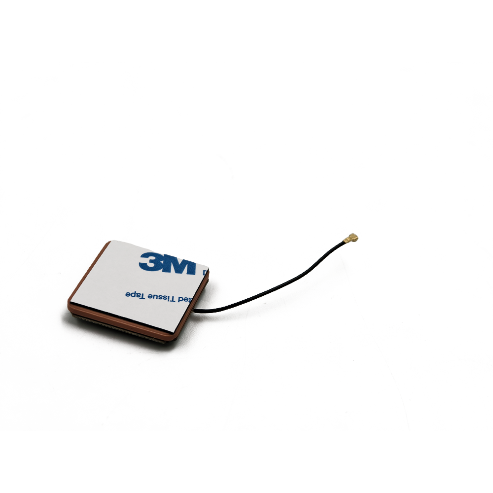
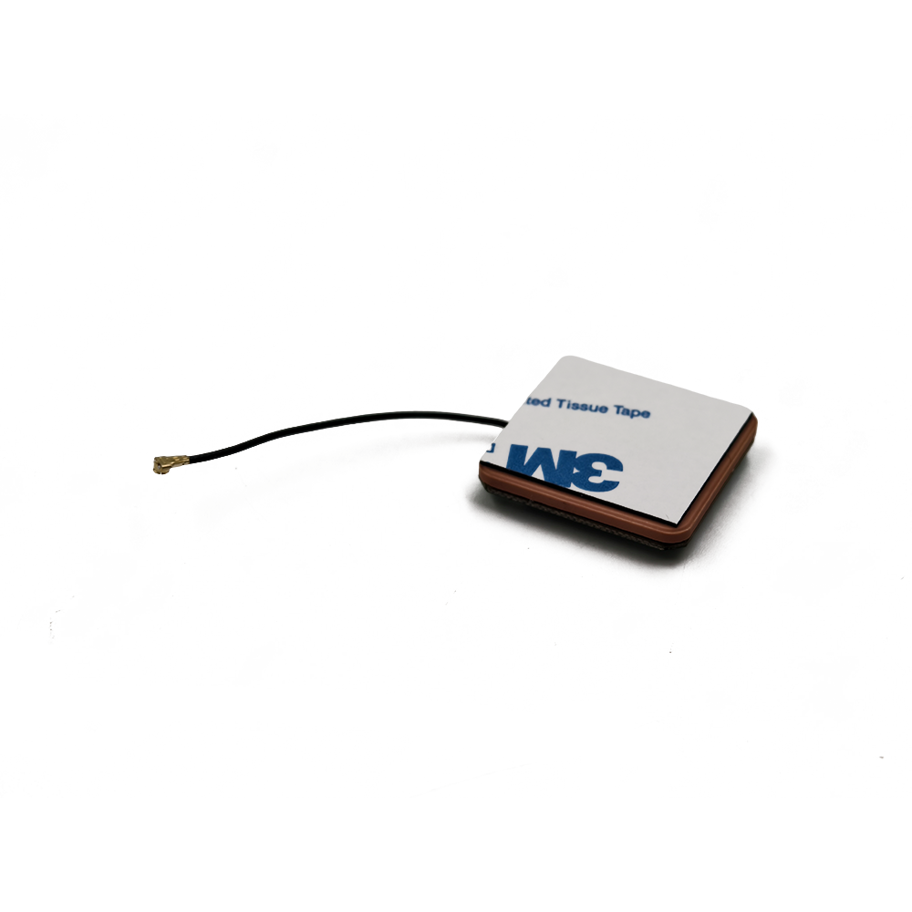
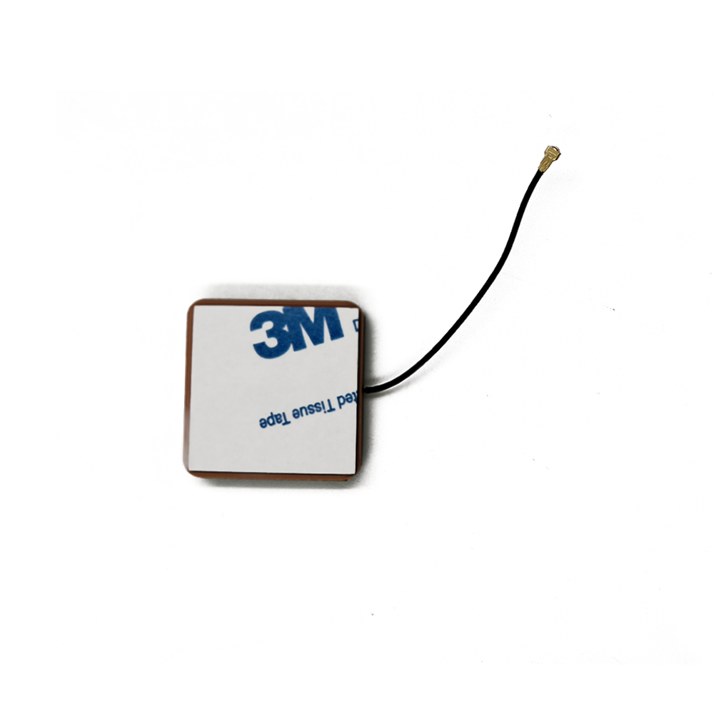
The construction of a miniature GNSS ceramic patch antenna is a precise and layered process, akin to creating a microscopic electronic sandwich where every layer has a critical electromagnetic function. The design is a careful ballet of material selection, geometric precision, and electronic integration, all aimed at maximizing performance within a minimal volume.
The Foundation: Ceramic Substrate
The core of the antenna is a block of ceramic material, typically a mixture of titanium dioxide or other metal oxides. This is not the fragile ceramic of a dinner plate but a highly engineered, sintered material with very specific properties. Its most important characteristic is its high dielectric constant (εr), which can range from 20 to over 90. A high εr reduces the wavelength of the radio waves within the material, allowing the radiating element (the patch) to be physically smaller for a given frequency. The ceramic is also chosen for its low loss tangent, meaning it absorbs very little of the RF energy, allowing it to be efficiently radiated or received. It must also have a stable temperature coefficient to ensure its performance doesn't drift significantly with changes in environmental temperature.
The Radiating Element: The Patch
On top of the ceramic substrate, a thin layer of conductive material (usually silver or copper) is printed or plated to form the radiating patch. This patch is typically square or circular, and its precise dimensions are the primary factor determining the antenna's resonant frequency. Even a micron-level deviation can detune the antenna. For antennas that cover multiple GNSS bands (e.g., L1 and L5), the patch may have a more complex shape with multiple feeds or slots to excite different modes of resonance.
The Ground Plane
The bottom layer of the ceramic block is metallized to form a continuous ground plane. This is a critical element that defines the antenna's radiation pattern. The ground plane acts as an electrical mirror, creating a directional pattern that radiates and receives preferentially in the hemisphere above the antenna. This is ideal for GNSS, as satellites are always located above the horizon. The size and quality of the ground plane provided on the device's PCB significantly impact the antenna's performance. A rule of thumb is that the PCB ground should extend at least a quarter-wavelength (~40mm at 1.5 GHz) around the antenna for optimal performance, though miniaturized designs often work with much less, accepting a trade-off in efficiency.
The Low-Noise Amplifier (LNA)
Mounted adjacent to the ceramic radiator, often on a small secondary PCB, is the LNA chip. This amplifier is the heart of an "active" antenna. Its job is to take the incredibly weak signal captured by the patch (around -130 dBm) and amplify it by 15 to 30 dB while adding the absolute minimum amount of internal electronic noise itself (measured as a low Noise Figure, often <1 dB). This amplification is crucial to overcome the losses in the transmission line (typically a thin coaxial cable like U.FL) that connects the antenna to the main GNSS receiver. The LNA requires a small DC power supply, which is almost always provided by the GNSS receiver module through the same coaxial cable via a "bias tee" circuit.
Protective Housing and Shielding
The entire assembly—ceramic patch, feed point, and LNA—is encapsulated in a protective housing. This is usually made of a plastic material that is transparent to RF signals (low loss tangent). Some designs include a metal shield or "can" over the LNA and surrounding circuitry to protect it from external electromagnetic interference (EMI) emanating from other components within the device, such as processors, memory, and wireless transceivers.
Feeding the Antenna
The antenna is connected to its feed point, which is where the electrical energy is transferred to and from the patch. The impedance at this point must be meticulously matched to the impedance of the feed line (typically 50 Ohms) to ensure maximum power transfer. This is achieved through careful design of the patch's geometry and often a matching network of tiny capacitors and inductors. Poor impedance matching results in reflected power (high VSWR) and significantly degraded performance.
The operation of a miniature ceramic patch antenna is an elegant demonstration of fundamental electromagnetic principles, scaled down and optimized for a specific purpose. Its primary job is to act as a resonant transducer for circularly polarized waves in the L-band.
Resonance: The Key to Reception
An antenna operates most efficiently when it is electrically resonant at the target frequency. Resonance occurs when the physical dimensions of the patch are precisely related to the wavelength (λ) of the desired radio wave. For a standard square patch, the resonant length is approximately half the wavelength within the dielectric material. The wavelength inside the ceramic is given by λ = λ₀ / √εr, where λ₀ is the free-space wavelength and εr is the dielectric constant. This is the magic of the high-εr ceramic: it shrinks the effective wavelength, allowing a physically small patch (e.g., 10mm) to resonate at a low frequency (1.5 GHz) where a free-space antenna would need to be around 100mm across.
Capturing Circular Polarization
GNSS satellites transmit signals that are Right-Hand Circularly Polarized (RHCP). This means the electric field of the radio wave rotates clockwise as it travels towards the antenna. The miniature patch antenna is designed to be sensitive to this specific polarization. This is typically achieved by feeding the patch at two points with a 90-degree phase difference between them, exciting two orthogonal modes that combine to create circular polarization. This design provides a natural advantage: many unwanted reflected signals (multipath) become reversed to Left-Hand Circularly Polarized (LHCP) or depolarized upon bouncing off the ground or buildings. The RHCP antenna is inherently less sensitive to these reflected signals, providing a first layer of filtering against a major source of positioning error.
Radiation Pattern
The metal ground plane beneath the ceramic substrate forces the antenna to radiate in a directional pattern, almost exclusively into the hemisphere above it. This is described as a "wide beamwidth" pattern, meaning it can receive signals from satellites across a broad range of elevation angles, from nearly the horizon to directly overhead. While not as focused as a high-gain antenna, this wide coverage is essential for a device whose orientation is constantly changing, like a smartphone or a watch. The trade-off is a lower peak gain compared to a larger antenna, but it ensures that at least some satellites are always in view.
The Role of the LNA and Filtering
The captured signal is incredibly weak. The integrated LNA amplifies this signal before any significant loss can occur in the downstream components. Furthermore, most active ceramic patches include some form of filtering, either as a separate component or integrated into the LNA design. This filtering is critical for rejecting out-of-band interference, particularly from strong nearby transmitters like cellular (4G/5G), Wi-Fi (2.4 & 5 GHz), and Bluetooth, which could otherwise overload the sensitive GNSS receiver and cause a loss of lock.
The Importance of the Ground Plane
The device's PCB ground plane is not a passive participant; it is an integral part of the antenna system. It directly influences the antenna's bandwidth, efficiency, and radiation pattern. A large, continuous ground plane provides a stable reference, leading to predictable performance. However, in miniaturized devices, space is limited, and the ground plane is often cut down, crowded, or irregular. This can detune the antenna, shift its resonance frequency, distort its pattern, and reduce its efficiency. Antenna designers must often simulate and design their patch to work with a specific minimum ground plane size, and device manufacturers must adhere to these layout guidelines strictly.
The miniature GNSS ceramic patch antenna offers a compelling set of advantages that have cemented its dominance in consumer electronics, but the relentless drive for smaller size introduces significant engineering challenges that must be carefully managed.
Advantages:
Extreme Miniaturization: This is the primary advantage. The use of high-dielectric ceramic allows for an antenna that is an order of magnitude smaller than a PCB trace antenna or a traditional quadrifilar helix antenna for the same frequency, enabling its integration into ever-smaller form factors like wearables and trackers.
Excellent Performance in a Small Package: Despite its size, a well-designed ceramic patch antenna can achieve good efficiency and a radiation pattern well-suited for consumer devices that are used in various orientations.
Mechanical Robustness: The sintered ceramic core and protective housing make the antenna highly resistant to vibration, shock, and physical deformation, which is far superior to a fragile helical antenna or a flexible PCB antenna.
Simplified Integration: For device manufacturers, sourcing a pre-tuned, pre-packaged antenna module simplifies the design process. The antenna comes as a single surface-mount device (SMD) component that can be automatically placed and soldered onto the PCB alongside other components, reducing assembly cost and complexity.
Cost-Effectiveness at Scale: While the ceramic material and LNA add cost, the design is highly manufacturable using standard processes. When produced in the millions of units for consumer markets, the per-unit cost becomes very low, making it an economical choice.
Challenges and Considerations:
Performance Trade-Offs: The fundamental law of antenna physics is that there is a direct trade-off between size, efficiency, and bandwidth. A smaller antenna inherently has narrower bandwidth and lower efficiency. Designers must carefully balance these parameters, often sacrificing support for some GNSS bands or accepting lower signal strength.
Ground Plane Dependence: The performance of a patch antenna is heavily dependent on the size and quality of the ground plane provided on the host device's PCB. A poor ground plane layout is the single most common reason for GNSS performance failure in a device. This limits the antenna's placement and requires careful collaboration between the antenna supplier and the device designer.
Thermal Sensitivity: While stable, the ceramic's dielectric constant still varies slightly with temperature. In extreme temperature ranges, this can cause a slight drift in the resonant frequency, potentially degrading performance. The LNA's gain and noise figure are also temperature-dependent.
Susceptibility to De-tuning: The antenna's performance is highly sensitive to its immediate environment. Placing it too close to metal components, batteries, or even the user's hand (a effect known as "hand-effect") can detune the antenna, pulling its resonance frequency away from the GNSS band and causing a severe drop in performance.
Limited Gain and Pattern Control: The wide, hemispherical pattern is good for coverage but offers less gain towards the zenith compared to a larger antenna. It also has less ability to reject multipath from low angles compared to a specialized geodetic antenna like a choke ring.
The miniature GNSS ceramic patch antenna is the workhorse of modern mass-market positioning, enabling a breathtaking array of applications. Its evolution is tightly coupled with the trends in the devices it empowers.
Ubiquitous Applications:
Smartphones and Tablets: The primary application. It enables mapping, location-based services, geotagging, and emergency (E911/eCall) functionality.
Wearables: Fitness trackers and smartwatches use them to map runs, rides, and hikes without needing a connected phone.
Personal and Asset Trackers: Small GPS trackers for pets, vehicles, luggage, and high-value assets rely entirely on these tiny antennas.
Drones and Robotics: Used for basic positioning, navigation, and return-to-home functions in consumer and prosumer drones.
In-Vehicle Systems: Telematics units, emergency call systems (eCall), and in-car navigation often use ceramic patches for their reliability and low profile.
IoT and M2M: Any Internet of Things device that needs location awareness, from agricultural sensors to smart city infrastructure, utilizes this technology.
Future Trends:
Multi-Band/Multi-Constellation Support: As GNSS receivers evolve to use L1, L2, L5, E1, E5, and B1 signals from all constellations for better accuracy and robustness, antennas must keep pace. Future miniature designs will need to cover a wider bandwidth (from 1176 MHz to 1610 MHz) without increasing in size, driving innovation in wideband patch design.
Tighter Integration (AiP - Antenna-in-Package): The next frontier is moving the antenna from the PCB directly into the same semiconductor package as the GNSS receiver chip itself. This would eliminate the coaxial cable and its associated losses, further reduce size, and shield the connection from external noise. This is a major research and development focus.
Enhanced Filtering and Coexistence: Devices are getting more crowded with radios (5G, Wi-Fi 6E/7, UWB). The need for better filtering within the antenna assembly to reject this powerful in-band and out-of-band interference will grow. Integrated filtering LNAs will become standard.
"De-sensing" Mitigation: A major challenge is the GNSS receiver being "de-sensed" (blinded) by a device's own cellular transmitter. Future designs may incorporate active cancellation techniques or more sophisticated filtering to operate simultaneously with 5G transmissions.
Improved Robustness to Environment: Research into new ceramic composites and design techniques will focus on making antennas less susceptible to de-tuning from the human body and nearby materials, making performance more consistent and predictable.
Conclusion
The miniature GNSS ceramic patch antenna is a testament to the ingenuity of RF engineering. It represents a perfect solution to a modern problem: how to embed high-frequency global positioning functionality into devices where space is the ultimate luxury. By leveraging the properties of advanced ceramics, it breaks the traditional size-frequency relationship, allowing a tiny object to resonate with satellites a fifth of the way to the moon.
Its success lies in its elegant compromise. It accepts the inherent trade-offs of lower gain and ground plane dependence to achieve its primary goal: providing "good enough" GNSS performance in an incredibly small, robust, and cost-effective package. This compromise has been overwhelmingly successful, enabling the location revolution that has transformed industries and daily life.
From a technical perspective, it is a sophisticated system-on-a-chip, combining materials science, electromagnetic theory, and analog electronics. Its performance is a delicate dance that depends not only on its own design but on the careful consideration of the entire device ecosystem in which it is placed.
As we move towards a future of even more connected and autonomous things, the demand for smaller, more efficient, and more reliable positioning will only intensify. The miniature ceramic patch antenna will continue to evolve, embracing new bands, deeper integration, and smarter filtering to remain the pervasive, invisible pillar of the precision that modern life has come to depend on. It is a foundational technology that, despite its size, carries the immense responsibility of connecting our world to the heavens.

 86 0755 2819 9597
Lucy Yang | lucy.y@toxutech.com
Nicole Li | nicole@toxutech.com
Dotty Zhao | sales04@toxutech.com
Global Business Director / Sales Team / Global Operations


 En
En Cn
Cn Korean
 Home >


