

-
Products -PCBA Manufacturing RF Connectors RF Cable Assemblys Embedded Antennas External Antennas Positioning Chips and Modules
RF Connectors

RF Cable Assemblys
Embedded Antennas
External Antennas
Positioning Chips and Modules


 Language


Language


In the vast and intricate ecosystem of Global Navigation Satellite Systems (GNSS), the antenna serves as the critical gateway, the first point of contact between the infinitesimally weak signals from satellites orbiting over 20,000 kilometers away and the sophisticated digital processors of a receiver. For Real-Time Kinematic (RTK) applications, which demand centimeter-level accuracy, this role is magnified in importance. Among the various antenna technologies vying for dominance in this space, the miniature ceramic patch antenna has emerged as the most ubiquitous, successful, and commercially viable solution, enabling the mass adoption of high-precision positioning across a myriad of industries and devices.
A patch antenna, in its fundamental form, is a type of radio antenna that is low-profile, lightweight, and easily manufacturable. It typically consists of a flat rectangular or circular sheet of metal (the "patch") mounted over a larger sheet of metal (the ground plane), separated by a dielectric substrate. When adapted for GNSS, this substrate is most often a specialized ceramic material, chosen for its critical electromagnetic properties. The "miniature" aspect refers to the relentless drive to reduce the size of these antennas, often to footprints of 25mm x 25mm or even smaller, making them ideal for integration into modern compact devices like drones, survey rovers, handheld controllers, and Internet of Things (IoT) sensors.
The rise of the ceramic patch antenna is a story of perfect alignment with market needs: performance, cost, and form factor. While other antennas like helices or choke rings may offer superior performance in specific metrics, the ceramic patch strikes an exceptional balance. It provides good right-hand circular polarization (RHCP), adequate gain, and a wide enough beamwidth to track satellites across the sky, all while being incredibly thin, inexpensive to produce in large volumes, and easy to integrate into a product's design. This has made it the de facto standard for integrating GNSS functionality into virtually everything.
Its role in RTK is particularly fascinating. RTK relies on measuring the phase of the carrier wave of the GNSS signal, a process incredibly sensitive to errors introduced by the antenna itself, notably Phase Center Variation (PCV). While early patch antennas struggled with this, advancements in design, simulation, and manufacturing have led to modern ceramic patches with remarkably stable phase centers. Through meticulous design and rigorous calibration, manufacturers can now produce patches that meet the stringent requirements of centimeter-level RTK, no longer confining this performance to large, expensive, survey-grade antennas.
Therefore, the miniature GNSS RTK ceramic patch antenna is not merely a component; it is an enabling technology. It has democratized precision, taking RTK from a specialized tool used by surveyors on tripods and putting it into the hands of farmers on tractors, engineers on drones, and developers creating the next generation of autonomous machines. Its overview is one of elegant engineering compromise, resulting in a product that is greater than the sum of its parts, powering the precise positioning revolution from the background.
The construction of a high-performance miniature GNSS RTK ceramic patch antenna is a sophisticated process that blends materials science, electromagnetic theory, and precision manufacturing. It is far more complex than a simple piece of metal on ceramic; it is a multi-layered system engineered to exacting specifications.
The Core Building Blocks:
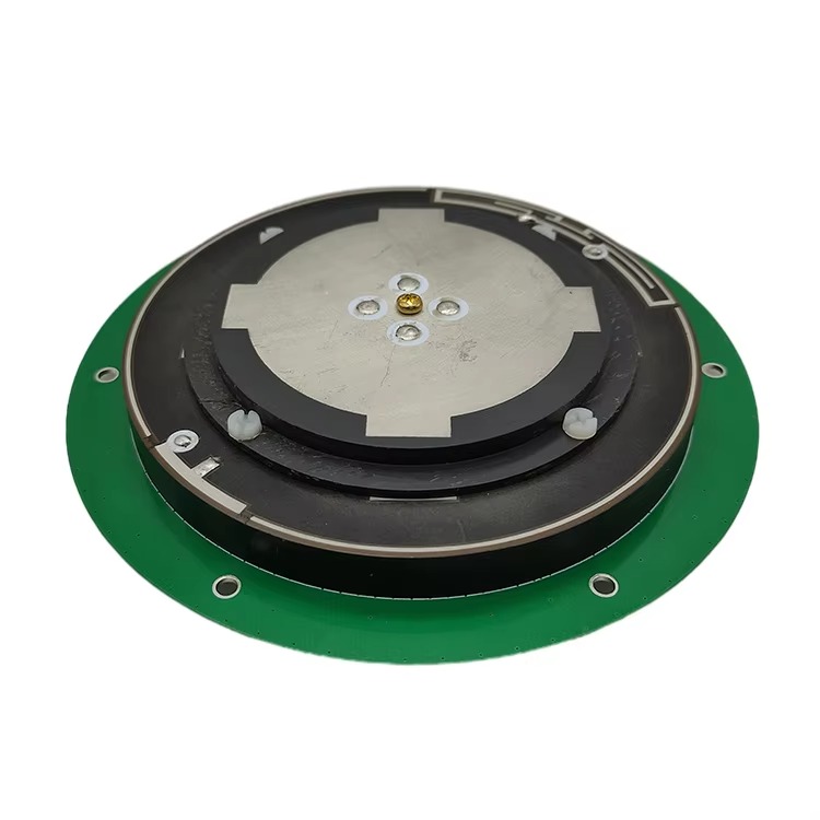
Ceramic Substrate: This is the heart of the antenna and the source of its name. The substrate is not a simple insulator; its properties are paramount.
Dielectric Constant (εr): Ceramics used are "high-K" materials, with εr typically ranging from 20 to 40. A high εr has a wavelength-shortening effect, allowing the resonant patch element to be physically much smaller for a given frequency (λ = λ₀ / √εr). This is the primary secret behind its miniaturization.
Loss Tangent (tan δ): This must be extremely low. A high loss tangent means the material itself absorbs and dissipates RF energy as heat, drastically reducing the antenna's radiation efficiency. Premium ceramics have exceptionally low loss tangents, ensuring most of the energy is radiated effectively.
Temperature Stability: The dielectric constant must remain stable over a wide temperature range (e.g., -40°C to +85°C). If it drifts, the antenna's resonant frequency will shift, detuning it and degrading performance.
Patch Radiator: This is a thin film of silver or other conductor printed onto the top surface of the ceramic. Its dimensions (length L and width W) primarily determine the resonant frequency. For a square patch, L ≈ λ₀ / (2 √εr). The precise geometry can be modified (e.g., with slots, notches, or probes) to optimize bandwidth, impedance matching, and to excite dual or triple resonances for multi-band operation (e.g., GPS L1, GLONASS G1, Galileo E1, BeiDou B1).
Ground Plane: A continuous layer of conductor on the bottom surface of the ceramic substrate. It serves two key functions: it acts as a reflector to direct the antenna's radiation pattern upwards towards the sky, and it defines the antenna's impedance characteristics. The size of the ground plane significantly influences the antenna's performance, especially its radiation pattern and gain.
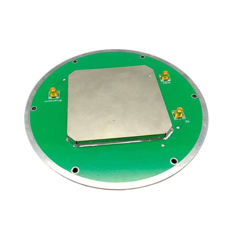
Feed Mechanism: This is how RF energy is coupled between the antenna and the transmission line (coaxial cable). The method is critical for achieving good impedance matching (a low Voltage Standing Wave Ratio - VSWR).
Probe Feed: A coaxial cable is soldered directly to the patch, with its inner conductor passing through a hole in the substrate and ground plane. This is effective but can be mechanically less robust and more labor-intensive.
Aperture-Coupled Feed: The patch is driven electromagnetically through a slot in the ground plane from a microstrip feedline on a separate underlying PCB. This allows for excellent optimization of bandwidth and impedance matching and provides isolation between the radiating element and the feed network.
Ceramic Edge Feed: A common and robust method for commercial patches where the feed is applied to the side of the ceramic block, making assembly easier.
The Integrated Active Antenna Assembly:
A standalone passive ceramic patch is only half of the solution. For GNSS RTK, it is always packaged as an active antenna:
Low-Noise Amplifier (LNA): This is mounted directly on the antenna's carrier PCB, millimeters away from the feed point. Its job is to amplify the extremely weak satellite signals (often below -130 dBm) before they are attenuated by the transmission cable. Its noise figure is paramount—typically below 1 dB—meaning it adds almost no noise of its own during amplification.
Bandpass Filter: Integrated into the PCB before or after the LNA, this filter rejects powerful out-of-band interference from cellular (4G/5G), Wi-Fi, and other RF sources that could saturate the LNA or the downstream receiver.
Power Conditioning: The antenna is powered via the coaxial cable (typically 3V or 5V DC). The PCB includes regulators and filters to ensure clean, stable voltage for the LNA.
Housing and Radome: The entire assembly is encapsulated in a plastic housing. The top part, the radome, is made from a material that is transparent to GNSS radio waves (low εr and low loss tangent) to protect the delicate ceramic element from physical damage, moisture (often rated IP67), and UV radiation.
The construction is a masterpiece of miniaturization and integration, transforming a simple resonant structure into a high-performance, robust, and self-contained system ready for deployment in demanding environments.
The operation of a ceramic patch antenna is governed by fundamental principles of resonance and radiation. Understanding these principles reveals both its strengths and the engineering challenges overcome to make it suitable for RTK.
Resonance and Radiation:
The patch antenna operates as a resonant cavity. The patch conductor and the ground plane form the two walls of this cavity, with the ceramic substrate filling the space between them. When RF energy is applied at the correct frequency, a standing wave is established between the radiating edges of the patch. The primary mode of operation is the TM₁₀ mode, where the length L of the patch is approximately half a wavelength within the dielectric (λ₀ / (2 √εr)). The radiation occurs from the fringing fields that extend beyond the edges of the patch into the surrounding space. This mechanism naturally produces a broad, hemispherical radiation pattern, which is ideal for viewing satellites across the entire sky.
Achieving Circular Polarization:
GNSS signals are Right-Hand Circularly Polarized (RHCP). A simple square patch excited at a single point produces a linear polarization. To create circular polarization, the patch must be excited in a way that generates two orthogonal modes with equal amplitude and a 90-degree phase difference. This is achieved through several techniques:
Single-Feed with Perturbations: The most common method for miniaturized antennas. By introducing a physical distortion in the patch—such as a truncated corner, a diagonal slot, or a notch—the geometry is made slightly asymmetric. This asymmetry splits the resonant frequency into two slightly different frequencies for two orthogonal modes. When operated at the midpoint between these frequencies, the required phase and amplitude conditions are met, resulting in circular polarization.
Dual-Feed: Two separate feed points are used, driven with a 90-degree phase shift. This technique offers wider axial ratio bandwidth (i.e., better quality circular polarization over a wider frequency range) but is more complex to implement in a miniaturized design.
The Crucial Concept of Phase Center:
For RTK, the most critical aspect of antenna performance is the stability of its Phase Center. The phase center is the apparent origin of the transmitted or received spherical wavefront. The receiver's carrier-phase measurements assume this point is fixed. However, in reality, the phase center moves slightly depending on the elevation and azimuth angle of the incoming satellite signal; this movement is called Phase Center Variation (PCV).
The Challenge for Patches: The phase center of a simple patch antenna is not a single point. It can vary by several millimeters. This is due to factors like the asymmetry of the feed, interaction with the edges of the finite ground plane, and the nature of the fringing fields. For standard positioning, this is irrelevant. For RTK, where a millimeter error corrupts the solution, it is catastrophic.
The Engineering Solution: Antenna manufacturers use advanced electromagnetic simulation software to meticulously optimize the patch geometry, feed location, and ground plane size to minimize PCV. Furthermore, every production antenna model is sent to an anechoic chamber for absolute calibration. Here, its precise phase center offset (PCO) and PCV pattern across all angles are measured and characterized. This data is published as an "antenna model" (e.g., in ANTEX format) that high-precision RTK software and receivers use to correct the raw measurements, effectively subtracting the antenna's inherent error. This calibration process is what elevates a standard ceramic patch to an "RTK-grade" component.
In essence, the working principle of an RTK ceramic patch is not just about resonating and radiating; it is about doing so with extreme consistency and predictability, allowing its imperfections to be precisely measured and mathematically removed in post-processing.
The miniature ceramic patch antenna dominates the GNSS market due to a powerful set of advantages, but its design necessitates careful management of inherent trade-offs and challenges.
Advantages:
Low Profile and Miniaturization: This is its foremost advantage. The high-dielectric ceramic substrate allows for a drastically reduced footprint and thickness (often just a few millimeters tall), enabling integration into sleek, modern devices where a helical antenna would be impractical.
Low Cost and High Volume Manufacturing: The design is highly amenable to automated printing and firing processes derived from the electronics industry. Ceramic patches can be produced in massive quantities at a very low unit cost, making high-precision GNSS economically viable for consumer and industrial applications.
Mechanical Robustness and Durability: The solid ceramic block is inherently rigid and, when potted within its housing, becomes highly resistant to vibration, shock, and physical impact. This makes it ideal for harsh environments on vehicles, agricultural machinery, and drones.
Ease of Integration: Its flat shape and simple single-cable connection (providing both DC power and RF output) make it straightforward for electrical and mechanical engineers to design into a product. It can be easily mounted on a PCB or onto a surface.
Good Performance: When well-designed, it provides excellent RHCP purity at zenith, good efficiency, and a wide hemispherical coverage pattern that captures satellites from horizon to horizon.
Challenges and Considerations:
Phase Center Variation (PCV): As discussed, this is the fundamental challenge. While manageable through calibration, it remains a inherent characteristic of the design. Its PCV is generally higher and more complex than that of a well-designed helical antenna, making the calibration data absolutely critical for RTK use.
Narrow Bandwidth: The high-Q resonant nature of the ceramic-loaded cavity inherently limits the instantaneous bandwidth. While techniques exist to broaden it, supporting all GNSS bands (L1, L2, L5, E6, etc.) often requires multiple stacked patches or more complex designs, increasing cost and size.
Performance at Low Elevation Angles: The radiation pattern can have reduced gain and a degraded axial ratio (the quality of its circular polarization) at low angles near the horizon. This makes it slightly more susceptible to low-angle multipath (reflected signals) compared to a helix, which has a deeper null below the horizon.
Ground Plane Dependence: The antenna's performance, particularly its impedance matching and radiation pattern, is influenced by the size and shape of the ground plane it is mounted on. For consistent performance, it must be used on the ground plane size specified by the manufacturer. Placing it on a different-sized metal surface can detune it and alter its phase center characteristics.
Thermal Sensitivity: Although ceramics are chosen for stability, all materials have some temperature coefficient. Extreme temperature swings can cause slight shifts in the dielectric constant, leading to minor drifts in the resonant frequency. High-end designs mitigate this with temperature-compensating materials.
In summary, the advantages of the ceramic patch are overwhelmingly centered on commercial and integration factors (cost, size, robustness), while its challenges are primarily performance-related (PCV, bandwidth). For the vast majority of applications, its advantages far outweigh its drawbacks, especially once its behavior is precisely calibrated and corrected.
The miniature ceramic patch antenna is the workhorse of modern GNSS, finding its way into an astonishing array of applications that form the backbone of today's geospatial and autonomous technologies.
Current Applications:
Precision Agriculture: Mounted on the roofs of tractors, sprayers, and harvesters for automated guidance and variable-rate application, dramatically improving efficiency and yield.
Unmanned Aerial Vehicles (UAVs/Drones): The ideal solution for drones due to its minimal size and weight. Used for aerial mapping, surveying, photogrammetry, LiDAR scanning, and agricultural spraying, providing the precise positioning needed for accurate data collection and autonomous flight.
Surveying and Mapping: Integrated into lightweight RTK rovers and base stations. Its ruggedness and reliability make it perfect for field surveyors who need a portable, durable solution.
Machine Control and Guidance: Used on construction equipment (bulldozers, graders, excavators) and mining machinery for grade control, enabling machines to work to design specifications without traditional stakes or strings.
Autonomous Vehicles and Robotics: Provides the fundamental absolute positioning input for research platforms, autonomous mobile robots in warehouses, and last-mile delivery vehicles.
Consumer and Industrial IoT: Deployed in asset tracking devices, timing modules, and personal safety devices where small size, low cost, and good enough precision are required.
Future Trends:
Multi-Band, Multi-Constellation Designs: The future is about "all-signal" reception. Trends are moving towards single ceramic elements that can natively support L1/L2/L5/L6 bands for all constellations through advanced, multi-resonant structures (e.g., stacked patches) or more sophisticated feeding networks, all within a miniaturized form factor.
Tighter Sensor Integration: The antenna will evolve from a standalone component into the core of a "Positioning Module." This module will co-package the antenna with the GNSS receiver chip, an inertial measurement unit (IMU), and potentially other sensors like cellular modems on a single board, providing a complete plug-and-play positioning solution.
Enhanced Multipath Mitigation: Research into advanced ground plane designs, such as integrated anti-jamming and anti-multipath techniques like controlled reception pattern antennas (CRPAs) in a low-profile form factor, will continue to improve performance in challenging urban environments.
Auxiliary Augmentation: Future antennas may include integrated connectors for external L-band antennas (e.g., for receiving SBAS or correction services like Atlas from TerraStar or StarFire from John Deere), making them a one-stop shop for all correction data.
AI-Optimized Design: The use of machine learning and genetic algorithms in electromagnetic simulation software will accelerate the optimization of patch geometries, leading to designs that achieve previously impossible combinations of bandwidth, efficiency, and phase stability for their size.
The ceramic patch antenna will continue to evolve, maintaining its dominance by integrating more functionality and performance into its iconic small, flat package, continuing to drive innovation in the world of precise positioning.
Conclusion
The miniature GNSS RTK ceramic patch antenna is a testament to the power of engineering pragmatism. It may not hold the title of the absolute best-performing antenna in every single metric—that crown might go to a large geodetic choke ring or a high-end helical design. However, it unquestionably wins the title of the most impactful.
Its success lies in its unparalleled ability to balance adequate high-performance with the trifecta of commercial realities: low cost, small size, and rugged reliability. It has taken the phenomenal accuracy of RTK technology out of the exclusive realm of specialized surveyors and democratized it, putting it into the hands and onto the machines of countless industries. It is the key component that has enabled the precision agriculture revolution, the commercial drone explosion, and the rapid advancement of autonomous systems.
By solving the critical challenge of phase center variation through meticulous design and comprehensive calibration, manufacturers have transformed a simple resonant structure into a precision instrument. It proves that in technology, the optimal solution is rarely the one that excels in a single dimension, but rather the one that masters the balance of all dimensions. The ceramic patch antenna is that master, and as it continues to evolve, it will remain the fundamental building block upon which our increasingly precise and automated world is built.

 86 0755 2819 9597
Lucy Yang | lucy.y@toxutech.com
Nicole Li | nicole@toxutech.com
Dotty Zhao | sales04@toxutech.com
Global Business Director / Sales Team / Global Operations


 En
En Cn
Cn Korean
 Home >


