

-
Products -PCBA Manufacturing RF Connectors RF Cable Assemblys Embedded Antennas External Antennas Positioning Chips and Modules
RF Connectors

RF Cable Assemblys
Embedded Antennas
External Antennas
Positioning Chips and Modules


 Language


Language


The vast and unforgiving expanse of the marine environment demands navigation technology that is not merely accurate, but fundamentally reliable and resilient. At the heart of this critical system lies the marine GNSS antenna, a specialized device whose performance can be the difference between a safe passage and a maritime incident. Unlike its terrestrial counterparts, a marine GNSS antenna is engineered for a specific and demanding purpose: to provide continuous, unwavering positional data regardless of the vessel's motion, the harshness of the environment, or its orientation on the open ocean. The capability for 360° signal reception is not a luxury in this context; it is an absolute necessity, ensuring that the vital link to the satellite constellations remains unbroken even as the vessel pitches, rolls, and yaws through the waves.
A marine GNSS antenna with 360° reception is a robust, weatherproof unit designed to receive signals from all available Global Navigation Satellite Systems (GNSS)—including GPS (USA), GLONASS (Russia), Galileo (EU), and BeiDou (China)—and provide a consistent, high-quality signal to the onboard chart plotter, autopilot, and other navigation instruments. The term "360° reception" refers to its ability to maintain a strong and stable signal lock on satellites across the entire hemispherical dome of the sky above the horizon. This is critically important because a vessel is a dynamic platform, constantly moving in six degrees of freedom: heave, sway, surge, pitch, roll, and yaw. A standard antenna with a narrower beamwidth could easily lose lock on satellites as the boat heels over in a sharp turn or pitches into a swell, leading to a temporary loss of position data or a degradation in accuracy at precisely the moment it is needed most.
The marine environment itself is the antenna's greatest adversary. It must be engineered to withstand a relentless assault of corrosive salt spray, constant UV radiation from the sun, driving rain, and extreme temperature fluctuations. Furthermore, it is subject to intense vibration from the vessel's engines and the impact of waves. Internally, it must contend with a unique set of challenges, including signal reflection (multipath) off the water's surface and the superstructure of the boat itself, as well as potential RF interference from the multitude of other electronic systems onboard, such as radars, VHF radios, and satellite communication systems.
To meet these challenges, the marine antenna is typically an active design, meaning it incorporates a built-in Low-Noise Amplifier (LNA). This LNA is crucial because it boosts the incredibly weak satellite signals immediately upon reception, before they are sent down a potentially long coaxial cable run to the chart plotter located in the cabin or bridge. This amplification ensures that the signal arrives at the receiver with sufficient strength and a preserved signal-to-noise ratio (SNR), overcoming the cable losses that would otherwise degrade performance.
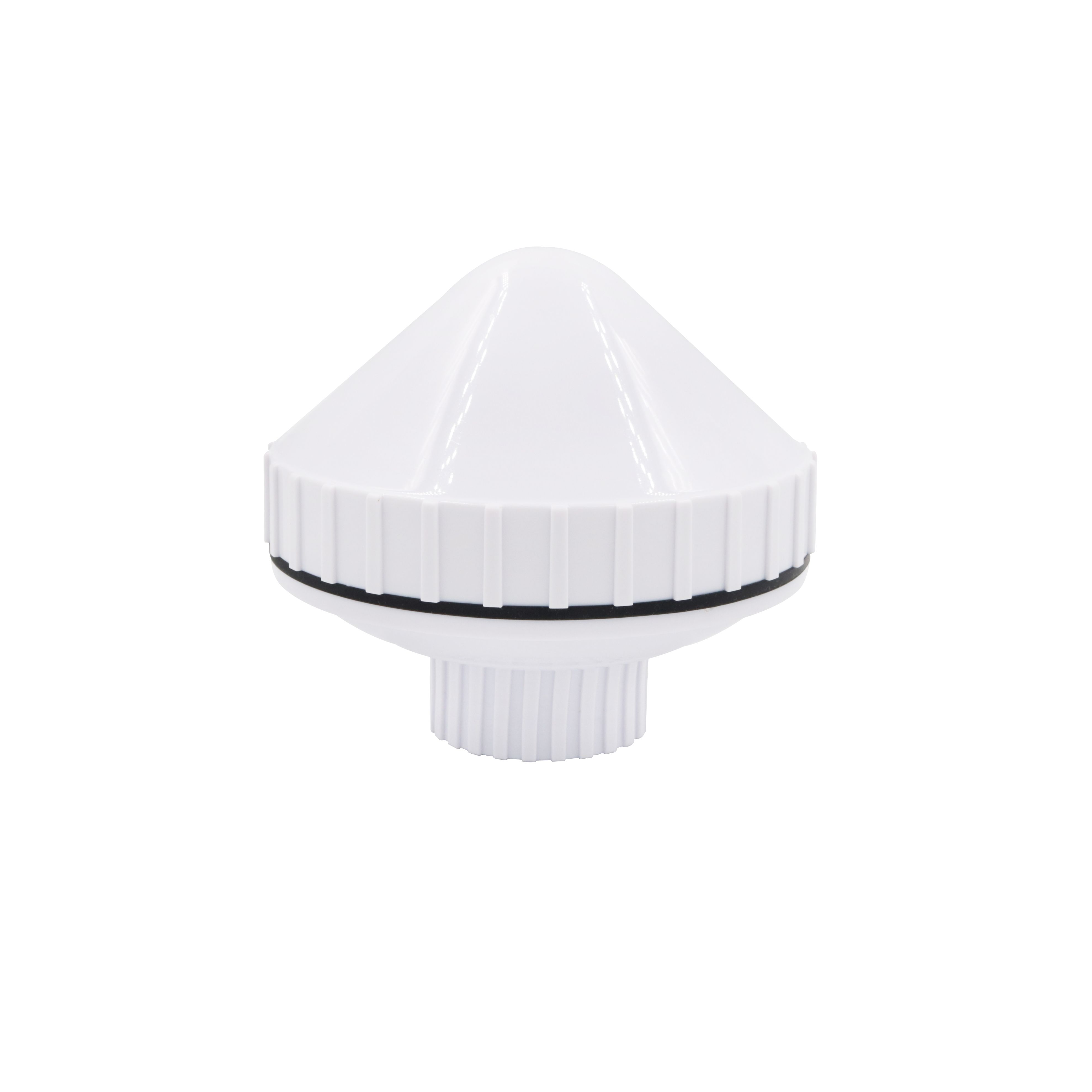
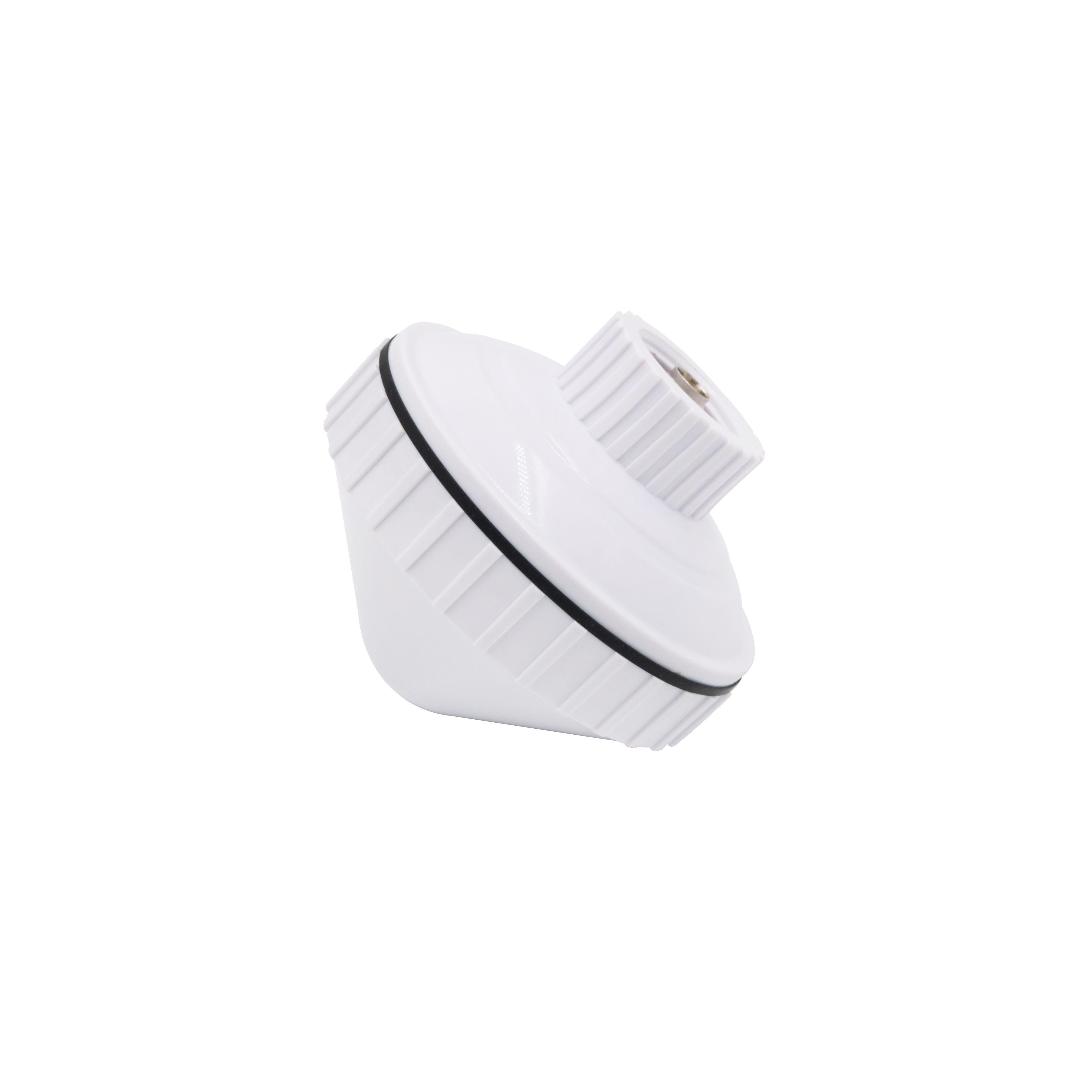
The physical form factor of these antennas is also distinct. They are often housed in a low-profile "puck" or a small cylindrical radome, constructed from materials like marine-grade stainless steel, UV-stabilized polycarbonate, and other composites resistant to corrosion. The design prioritizes a low aerodynamic profile to minimize wind resistance and avoid being snagged by lines or rigging.
In essence, the marine GNSS antenna with 360° reception is the unsung hero of modern maritime navigation. It is the primary sensor, the unwavering eye on the sky that translates whispers from orbiting satellites into a precise and reliable position on a chart. Its value is measured not in its complexity, but in its steadfast reliability, providing the captain and crew with the confidence to navigate safely, efficiently, and with certainty, no matter what conditions the sea may present.
The design and construction of a marine GNSS antenna with 360° reception is a meticulous exercise in balancing advanced electromagnetic performance with brutal environmental ruggedization. Every material, every seal, and every internal component is selected and assembled to create a hermetically sealed, high-performance unit capable of surviving the most aggressive marine conditions while delivering a pristine signal.
1. The Radiating Element: The Engine of Hemispherical Coverage
The core of the antenna is its radiating element, responsible for the crucial 360° coverage. The most common and effective designs are:
Quadrifilar Helix (QFH): This is a premier design for marine applications. It consists of four separate helical elements wound in a precise pattern and fed with signals that are 90 degrees out of phase. This phasing inherently generates the required Right-Hand Circular Polarization (RHCP) and produces a naturally wide, hemispherical radiation pattern. Its gain is very consistent from the horizon up to the zenith, making it exceptionally resistant to signal dropouts caused by vessel motion.
Crossed-Drooping Dipoles: Another prevalent design involves two pairs of dipoles, crossed at 90 degrees and mounted over a ground plane. The dipoles are "drooped" or angled downward, which widens the beamwidth and optimizes the pattern for excellent low-elevation satellite reception, which is vital on the open ocean where the horizon is a flat circle.
2. The Ground Plane: The Foundation for Performance
Beneath the radiating element lies a solid metal ground plane, typically integrated into the antenna's base. This is not merely a structural element; it is a critical electromagnetic component. It acts as a reflector to direct radiation upward, provides a stable electrical reference point, and is fundamental in shaping the antenna's radiation pattern to reject multipath signals arriving from below the horizon. Its size and integrity directly influence the antenna's gain and axial ratio.
3. The Low-Noise Amplifier (LNA): The Active Heart
Virtually all marine antennas are active. A high-performance LNA is mounted on a small PCB within the sealed enclosure. Its specifications are paramount:
Low Noise Figure (< 2 dB, often < 1.5 dB): It must add minimal self-generated noise to avoid degrading the signal-to-noise ratio (SNR) of the faint satellite signals.
High Gain ( typically 26-40 dB): This is essential to overcome signal loss in the long coaxial cable runs common on boats, which can easily be 10-20 meters from the mast to the chart plotter.
Robustness and Linearity: It must operate reliably across a wide temperature range and withstand vibration. It must also remain linear and not distort in the presence of strong out-of-band signals from onboard radars or radios.
4. The Environmental Fortress: Sealing and Ruggedization
This is what truly defines a marine-grade antenna. The sealing strategy is multi-layered and exhaustive:
The Radome: The outer shell is molded from high-grade, RF-transparent plastic. Materials like polycarbonate or ABS are chosen for their impact resistance and, critically, their UV stabilization to prevent yellowing, clouding, and embrittlement after years of sun exposure.
The Base: The base is typically machined from marine-grade stainless steel (e.g., 316-grade) or die-cast aluminum with a corrosion-resistant finish. This provides a robust platform for mounting and protects against saltwater corrosion.
O-Ring Seals: The critical interface between the radome and the base is sealed with a high-quality silicone or EPDM O-ring, creating a water-tight and air-tight seal that is the first line of defense against moisture ingress.
Potting: The internal cavity, containing the LNA board and feed connections, is often completely filled with a waterproof polyurethane or epoxy potting compound. This encapsulates the electronics, protecting them from the effects of humidity, condensation, thermal cycling, and physical shock from vibration and impact. It also prevents any internal movement that could break solder joints.
The Cable Gland: The point where the coaxial cable exits the antenna is a critical vulnerability. It is sealed with a robust, strain-relief cable gland that clamps tightly onto the cable's outer jacket, preventing water from wicking along the cable into the antenna and providing mechanical strength.
5. The Cable and Connector
The antenna is supplied with an integrated, pre-attached cable. This cable is itself specially rated for marine use, with a UV-resistant and waterproof outer jacket. The connector at the end (commonly TNC or SMA) is often made of stainless steel and includes a protective rubber cap to prevent corrosion when not in use.
The entire assembly process is followed by rigorous testing. Units are subjected to environmental stress tests, including salt spray chambers, thermal cycling, and vibration testing. RF performance is verified in anechoic chambers to ensure the gain, pattern, and voltage standing wave ratio (VSWR) meet the stringent specifications required for reliable marine navigation. The result is a device that is as much a piece of marine safety equipment as it is a sophisticated electronic sensor.
The operation of a marine GNSS antenna is a sophisticated interplay of electromagnetic theory and practical engineering, all contained within a ruggedized shell. Its working principles are dedicated to one overarching goal: to capture GNSS signals from any point in the sky with consistent gain and purity, and to deliver a robust, amplified signal to the receiver, ensuring continuous and accurate positioning on a dynamic platform.
The Science of Hemispherical Coverage
The fundamental requirement for 360° reception is achieved through a specific radiation pattern. Unlike a directional antenna that focuses energy in a narrow beam, the marine antenna is designed to have a wide, hemispherical pattern. Imagine a dome placed over the antenna; the ideal pattern provides strong, uniform gain across this entire dome. This ensures that:
Satellites are acquired and tracked reliably regardless of vessel attitude. As the boat rolls 30 degrees to port, the antenna's view of the sky shifts. A satellite that was previously at a 60° elevation might now be at 30°. The antenna's consistent gain across this angular range means the signal strength remains stable, preventing loss of lock.
Low-elevation satellites are utilized effectively. On the open ocean, the sky view is a full 360° circle on the horizon. Many satellites will be at relatively low elevations. The antenna's pattern is optimized to maintain good gain down to about 5° above the horizon, maximizing the number of usable satellites and improving the geometry of the solution, which directly enhances accuracy.
The Quadrifilar Helix (QFH) in Action
In a QFH design, the four helical elements are fed with signals that are 90 degrees out of phase. This phasing creates a rotating electric field vector that perfectly matches the Right-Hand Circular Polarization (RHCP) of the incoming GNSS signals. This design inherently produces a very wide beamwidth. The phase progression along the length of the helices ensures that the antenna is sensitive to signals from a very wide range of angles, making it exceptionally forgiving to platform motion.
Multipath Rejection: Fighting the "Ghost" Signals
A significant challenge in the marine environment is multipath—the phenomenon where a signal arrives at the antenna via two paths: the direct line-of-sight path and a reflected path off the surface of the water or the boat's superstructure. The reflected signal is delayed, corrupting the precise timing measurement and causing positioning errors. The marine antenna combats this in two ways:
Radiation Pattern Shaping: The antenna's pattern is designed to have very low gain below the horizon. Since multipath signals typically arrive at low or negative elevation angles, they are naturally attenuated by the antenna itself before they can enter the signal chain.
Circular Polarization Discrimination: The antenna is designed to receive RHCP signals. When a GNSS signal reflects off a surface, its polarization often becomes partially elliptical or even reverses to Left-Hand Circular Polarization (LHCP). The antenna is inherently less sensitive to these reflected, polarization-scrambled signals, providing a second layer of defense.
The Role of the Active Component: The LNA
The integrated Low-Noise Amplifier is fundamental to the system's operation. Its functions are critical:
Overcoming Cable Loss: The primary practical reason is to compensate for the significant signal attenuation that occurs in the coaxial cable run. On a sailboat, the cable from the masthead to the chart plotter can be 15-20 meters long. The LNA's high gain (e.g., 30 dB) boosts the signal to a level that can easily withstand this journey without falling below the receiver's sensitivity threshold.
Preserving Signal-to-Noise Ratio (SNR): The LNA's low noise figure is its most important specification. By providing clean amplification at the very beginning of the signal chain, it "locks in" a high SNR. Any loss that occurs after the LNA (in the cable) attenuates both the signal and the noise equally, preserving the SNR. If the cable loss occurred before amplification, it would degrade the SNR irrecoverably.
The Complete Signal Journey
Capture: RHCP signals from multiple GNSS satellites, arriving from various angles, induce currents in the radiating element (QFH or dipole).
Rejection: Low-angle multipath signals are attenuated by the antenna's radiation pattern.
Amplification: The tiny signals are immediately amplified by the integrated LNA with minimal added noise.
Transmission: The amplified signals travel down the ruggedized coaxial cable to the GNSS receiver (chart plotter).
Processing: The receiver uses the signals from multiple satellites to compute a precise position, velocity, and time (PVT) solution.
Action: This data is displayed on the chart plotter and fed to the autopilot to maintain course.
The antenna's working principle is thus one of selective, amplified, and stable reception. It ensures that the receiver is fed a strong, clean, and continuous stream of data, enabling it to provide the navigator with a trustworthy position fix upon which all other decisions depend.
The marine GNSS antenna with 360° reception offers a compelling set of advantages that make it the undisputed standard for maritime navigation. However, achieving this performance in such a hostile environment introduces a distinct set of challenges and trade-offs that manufacturers and users must navigate.
Advantages
Uninterrupted Signal Reception on a Dynamic Platform: This is the paramount advantage. The wide, hemispherical radiation pattern ensures continuous tracking of satellites regardless of the vessel's pitch, roll, and yaw. This prevents the dreaded "loss of position" alarm on the chart plotter during sharp maneuvers or in heavy seas, which is critical for safety and for maintaining autopilot control.
Exceptional Environmental Ruggedness: Built to true marine standards (e.g., IPx7/IPx8, NMEA 2000 requirements), these antennas are virtual fortresses. They are completely sealed against saltwater immersion, driven rain, and humidity. Their UV-stabilized radomes resist sun damage, and their corrosion-resistant materials ensure a long service life in the most punishing conditions. This ruggedness translates directly to reliability and peace of mind.
Superior Multipath Rejection: The combination of a well-defined radiation pattern (with low gain below the horizon) and the use of circular polarization provides inherent rejection of signals reflected from the water's surface and the boat's own deck. This results in a cleaner signal and a more accurate position solution, reducing the small, jittering errors that can be caused by multipath.
Integrated Signal Amplification: The built-in LNA is a major system-level benefit. It allows for long cable runs without signal degradation, giving installers flexibility in mounting the antenna in the optimal location (e.g., masthead for best view) and placing the display unit in the most convenient location (e.g., at the helm). It ensures the receiver always gets a strong signal.
Multi-GNSS Support for Enhanced Reliability: Modern marine antennas receive all major constellations (GPS, GLONASS, Galileo, BeiDou). This provides massive redundancy. If signals from one constellation are temporarily blocked or degraded, the receiver can seamlessly use signals from another, maintaining a high-integrity position fix. This significantly improves availability and accuracy.
Ease of Installation and Standardization: The standard form factor (puck or low-profile radome), standard connectors (TNC, SMA), and pre-attached cable make installation straightforward. Magnetic or bolt-through mounts offer flexible installation options on various boat surfaces.
Challenges and Limitations
Cost: The use of high-grade materials (marine stainless steel, specialized plastics), the complex internal design, the high-performance LNA, and the rigorous sealing and potting processes make marine antennas considerably more expensive than consumer-grade antennas. They are an investment in safety and reliability.
Power Requirement: As an active antenna, it requires a DC power source, which is supplied from the chart plotter or a separate power injector through the coaxial cable (via a bias-T). This adds a layer of complexity to the installation and means that a fault in the antenna or cable could potentially affect the connected device.
Physical Size and Mounting Considerations: While low-profile, the antenna still requires a clear, unobstructed 360° view of the sky. Finding an optimal mounting location away from shadows cast by masts, radar arches, and other equipment can be challenging on some boats. Furthermore, its location makes it susceptible to damage from docks, bridges, and bird strikes.
Vulnerability to RF Interference: The very amplification that makes the LNA beneficial can also be a drawback. The high-gain front end can be susceptible to overload from strong nearby transmitters, such as VHF radios, cellular boosters, or radar systems. While good designs include filtering, improper installation too close to other antennas can lead to desensitization or complete jamming of the GNSS receiver.
Cable Integrity: The fixed cable, while rugged, is a potential point of failure. If it is damaged during installation or by chafing over time, it can allow water to ingress, leading to corrosion and failure. The connector at the other end must also be kept clean and protected to prevent corrosion, which can cause signal loss and voltage drop.
Performance Trade-Offs: The wide beamwidth that provides stability comes at the cost of peak gain. A marine antenna will typically have a lower peak gain than a similarly sized directional patch antenna. This is a deliberate trade-off; consistency of signal across all angles is valued far more than strong signal from one direction and weak signals from others.
In conclusion, the advantages of the marine GNSS antenna are overwhelmingly focused on reliability and performance in the dynamic marine environment. The challenges are primarily related to cost, installation diligence, and the inherent trade-offs of a wide-beam design. For any serious mariner, the advantages represent not just benefits but essential requirements for safe navigation, making the challenges a necessary and worthwhile consideration.
The marine GNSS antenna with 360° reception is the cornerstone of a vast array of electronic systems on modern vessels. Its applications extend far beyond simply displaying a boat's position on a chart; it is a critical data source that enables automation, safety, and data collection. As marine technology evolves, the role of this antenna is expanding and adapting to new challenges and opportunities.
Applications
Electronic Chart Plotting and Primary Navigation: This is the fundamental application. The antenna provides the precise position data that allows a chart plotter to display the vessel's location in real-time on a digital nautical chart. This is the primary tool for situational awareness, allowing the navigator to see hazards, aids to navigation, and the intended course relative to the boat's position.
Autopilot and Steering Control: The autopilot is one of the most critical systems dependent on the GNSS antenna. The autopilot uses the precise position and, crucially, the heading and speed-over-ground data derived from the GNSS signal to steer a pre-determined course. The stability of the antenna's signal is paramount here; any dropout or glitch could cause the autopilot to steer erratically. The 360° reception ensures the autopilot receives continuous data even in heavy seas.
Automatic Identification System (AIS): AIS is a collision avoidance system that broadcasts a vessel's identity, position, course, and speed to other nearby vessels and to shore stations. The accuracy and reliability of this data are entirely dependent on the GNSS antenna. A failure or degradation of the antenna signal compromises the effectiveness of the entire AIS system, a critical safety tool.
Marine Radar Overlay: Modern radar systems can overlay the vessel's GPS track and waypoints onto the radar display. This fusion of data provides immensely improved situational awareness, allowing the navigator to easily identify which radar target is a specific navigation buoy or correlate a radar echo with a charted object. This requires a continuous and accurate feed from the GNSS antenna.
Performance Monitoring and Instrumentation: On sailing and motor yachts, the GNSS data is fed to multi-function displays (MFDs) to show accurate speed over ground (SOG) and course over ground (COG). This is essential for racing, fuel efficiency monitoring, and voyage planning.
Fishing and Resource Management: Commercial fishing vessels use precise GNSS data to return to exact fishing grounds, track tow paths for trawling, and meet reporting requirements for catch locations. Government agencies use the data for resource management and monitoring regulated areas.
Future Trends
Multi-Band GNSS Reception: The next generation of marine antennas is moving beyond L1 frequency reception. Multi-band antennas that also receive the L5 and L2 bands (from GPS, Galileo, etc.) will become standard. This will provide even greater accuracy (sub-meter) and breathtaking resilience to multipath and ionospheric interference, further enhancing safety and enabling new applications like precise docking assistance.
Integration with Inertial Navigation Systems (INS): The future lies in sensor fusion. Marine GNSS antennas will be increasingly integrated with miniaturized Motion Reference Units (MRUs) containing accelerometers and gyroscopes. During brief GNSS outages (e.g., under a bridge or due to intense wave action blocking the sky), the INS will provide dead reckoning, ensuring continuous positioning and preventing the autopilot from disengaging.
Advanced Interference Mitigation and Cybersecurity: The threat of GNSS jamming (accidental or intentional) and spoofing (where a false signal tricks the receiver) is growing. Future antennas will incorporate more sophisticated filtering and may evolve into Controlled Reception Pattern Antennas (CRPAs) that can actively nullify interference sources. This will be a critical step towards resilient PNT (Positioning, Navigation, and Timing).
The Role in Maritime Autonomous Surface Ships (MASS): As the industry moves towards autonomy and remotely operated vessels, the GNSS antenna will become even more critical. It will be the primary source of absolute position for the autonomous control system, requiring unprecedented levels of integrity, redundancy, and resilience to ensure the safe operation of unmanned vessels in crowded waterways.
Smaller, Smarter, and More Integrated Form Factors: Antennas will continue to become smaller and more low-profile. We will also see the rise of "integrated antenna systems" where a single housing contains elements for GNSS, VHF, AIS, and cellular, reducing deck clutter and simplifying installation. These systems will include built-in networking and diagnostics.
Enhanced Global Correction Services: Access to satellite-based augmentation systems (SBAS) like WAAS and EGNOS is standard. The future will see wider adoption of precise point positioning (PPP) services delivered via satellite or cellular, providing decimeter-level accuracy globally without the need for a local base station, a major benefit for blue-water cruisers.
The marine GNSS antenna is evolving from a simple receiver into an intelligent, resilient, and integrated PNT hub. Its future is one of greater accuracy, unwavering reliability, and enhanced functionality, solidifying its role as the indispensable guardian of maritime safety and efficiency.
Conclusion
The marine GNSS antenna with 360° signal reception is far more than a simple accessory on a boat; it is a fundamental pillar of modern maritime safety, navigation, and operational efficiency. Its value is measured not in its technical specifications alone, but in the confidence it instills in the mariner—the confidence to know one's position with certainty, to trust the automation of an autopilot, and to navigate safely through confined waters or across featureless oceans, regardless of the weather or the sea state.
Its design and construction represent a masterclass in engineering for reliability. It is a device where electromagnetic performance is perfectly balanced with environmental ruggedization. The choice of a quadrifilar helix or crossed-dipole radiating structure is a deliberate selection for unwavering hemispherical coverage, prioritizing consistent performance across the entire sky over peak gain in a single direction. The integration of a low-noise amplifier is a recognition of the practical realities of boat installation, ensuring signal integrity over long cable runs. And every other aspect of its construction—the marine-grade metals, the UV-stabilized radome, the precision O-rings, and the rugged potting compound—is a direct and calculated response to the brutal realities of the marine environment.
The advantages it provides are not mere conveniences; they are operational necessities. The guarantee of continuous signal reception during vessel motion is the bedrock upon which automated steering and accurate chart plotting are built. Its inherent resistance to multipath ensures that the position on the screen is a true reflection of the vessel's location and not a "ghost" created by a reflection off the water. The multi-GNSS capability provides a robust safety net through signal redundancy.
While challenges exist—such as cost, installation considerations, and vulnerability to interference—these are not weaknesses but rather the defined parameters within which the antenna must operate. They are the known variables that careful installation and quality equipment are designed to overcome.
Looking to the future, the role of this antenna is only set to expand and deepen. It will evolve from a receiver of L1 signals to a multi-band PNT hub, from a standalone component to an integrated part of a sensor-fused navigation system, and from a simple tool into a critical enabler of maritime autonomy. Its core mission, however, will remain unchanged: to provide the single, stable, and trustworthy data point of position from which all other navigational decisions flow.
In conclusion, the marine GNSS antenna with 360° reception is a testament to the successful application of advanced technology to a specific and demanding human need. It is a unsung hero that works silently and ceaselessly, translating whispers from medium Earth orbit into the confident progress of a vessel across the chart. It is a technology that has become so indispensable that its presence is assumed, and its true value is only fully appreciated when everything else is in motion, and it alone remains the fixed point of reference.

 86 0755 2819 9597
Lucy Yang | lucy.y@toxutech.com
Nicole Li | nicole@toxutech.com
Dotty Zhao | sales04@toxutech.com
Global Business Director / Sales Team / Global Operations


 En
En Cn
Cn Korean
 Home >


