

-
Products -PCBA Manufacturing RF Connectors RF Cable Assemblys Embedded Antennas External Antennas Positioning Chips and Modules
RF Connectors

RF Cable Assemblys
Embedded Antennas
External Antennas
Positioning Chips and Modules


 Language


Language


In the realm of modern geospatial technology, precision is not just a luxury; it is an absolute necessity. From enabling autonomous vehicle navigation to revolutionizing agricultural practices and streamlining construction projects, the ability to determine one's position on Earth with centimeter-level accuracy has become a cornerstone of technological progress. At the heart of this revolution lies the Global Navigation Satellite System (GNSS) Real-Time Kinematic (RTK) antenna, and specifically, its most versatile and user-friendly mobile variant: the magnetic-mount GNSS RTK car antenna.
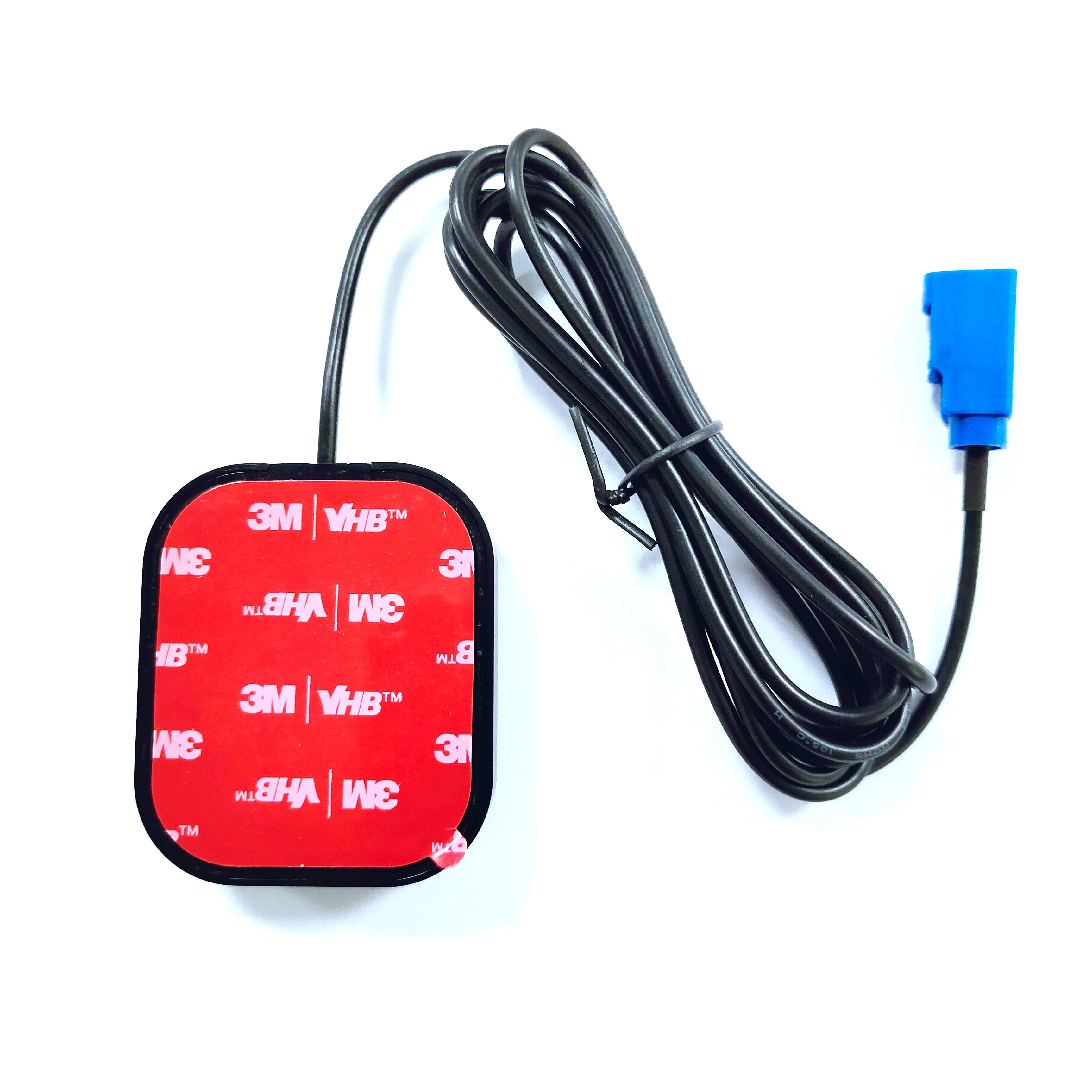
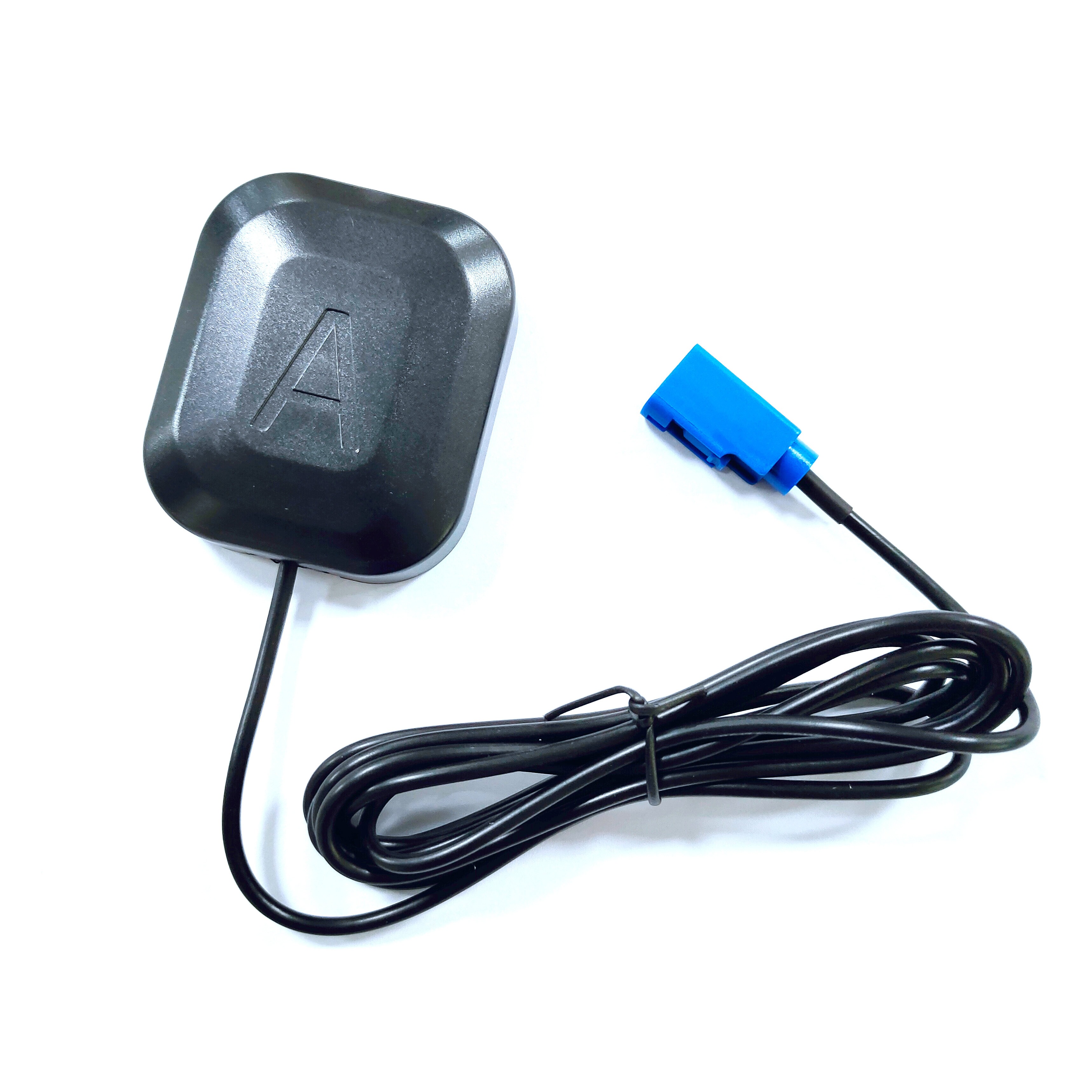
A magnetic-mount GNSS RTK car antenna is a highly specialized geodetic-grade antenna designed to be rapidly deployed on the metallic roof of a vehicle. Its primary function is to receive extremely weak signals from multiple satellite constellations—such as GPS (USA), GLONASS (Russia), Galileo (EU), and BeiDou (China)—and, crucially, to facilitate the RTK correction process that elevates standard GNSS accuracy from meter-level to centimeter-level. The "magnetic-mount" aspect refers to its integrated powerful neodymium magnet base, which allows for secure, temporary attachment to any ferromagnetic surface (like a car roof or trunk) without the need for drilling holes or permanent installation.
This device is far more than a simple signal receiver. It is a sophisticated piece of RF (Radio Frequency) engineering. Unlike consumer-grade GPS antennas found in smartphones or standard car navigation systems, an RTK antenna is designed with a specific focus on signal integrity, phase center stability, and multipath mitigation. It must accurately capture the carrier phase of the satellite signal, which is the key to RTK's high precision. The antenna's design ensures that this phase measurement is as stable and uncontaminated as possible, a critical requirement when dealing with corrections that are measured in millimeters.
The typical ecosystem for this antenna involves a pair of receivers: a base station and a rover. The base station is set up over a known, precisely surveyed point. It calculates the error in the satellite signals it receives by comparing its known position to the position derived from the satellites. It then broadcasts these error corrections. The magnetic-mount antenna, acting as the rover antenna on a vehicle, receives both the raw satellite signals and the correction data from the base station (often via a cellular modem). The rover's internal processor then applies these corrections in real-time to its own satellite observations, resolving the integer ambiguities in the carrier phase measurements to compute its position with astounding accuracy.
The applications for such a device are vast and growing. They are the eyes for precision agriculture, guiding tractors along sub-inch repeatable paths. They are the foundation for machine control in construction, guiding bulldozers and graders according to a digital design model. They are critical for mobile mapping systems, LiDAR units, and drone platforms that require a precise geospatial tag for every data point they collect. They are also increasingly used in emerging autonomous vehicle testing and ADAS (Advanced Driver-Assistance Systems) development.
In summary, the magnetic-mount GNSS RTK antenna is a gateway technology. It democratizes access to high-precision positioning by removing the barrier of complex installation. It represents a perfect synergy of convenience and cutting-edge performance, enabling a mobile platform to become a precise geospatial data collection or action unit within minutes. Its role is indispensable in transforming raw satellite data into a reliable, centimeter-accurate truth upon which critical decisions and automated processes depend.
The design and construction of a magnetic-mount GNSS RTK antenna are a meticulous balance of advanced electromagnetic theory, robust materials science, and practical ergonomics. Every component is optimized for a single goal: to provide a stable, precise, and unchanging reference point for measuring the phase of incoming GNSS signals, even in the harsh environment of a moving vehicle.
1. The Radiating Element: The Heart of the System
The core of the antenna is its radiating element, responsible for capturing the right-hand circularly polarized (RHCP) signals from satellites. This is typically achieved using a patched antenna design. An array of carefully shaped copper patches is etched onto a dielectric substrate. The size, shape, and spacing of these patches are precisely calculated to resonate at the specific L-band frequencies used by GNSS systems (e.g., L1, L2, L5, and others for multi-frequency operation). The multi-frequency capability is crucial for RTK, as it allows the receiver to better model and cancel out ionospheric delay, a major source of error. The element is housed within a cavity to control the radiation pattern and improve gain.
2. The Ground Plane: Stability and Multipath Rejection
Beneath the radiating element lies a critical component: the ground plane. This is typically a solid metal disc. Its primary functions are:
Defining the Radiation Pattern: It forces the antenna to have a directional pattern upward towards the sky, maximizing gain for low-elevation satellites and rejecting signals from below the horizon.
Multipath Mitigation: This is its most important role. Multipath error occurs when a satellite signal reflects off the ground, buildings, or the vehicle itself before reaching the antenna. These reflected signals are delayed and can corrupt the precise phase measurement. A well-designed ground plane, often with serrated or corrugated edges (a choke ring design in high-end models), creates a destructive interference pattern for signals arriving at low angles, effectively "choking" them out. This ensures the antenna only "sees" direct line-of-sight signals.
3. The Radome: Protection and Signal Transparency
The entire internal assembly is protected by a outer shell or dome, known as a radome. This is not just a simple plastic cover. It must be mechanically rugged to withstand impact, weatherproof (typically IP67 or higher rated), and UV resistant to prevent degradation from sun exposure. Critically, it must be electromagnetically transparent at GNSS frequencies. Any material placed over an antenna can detune it or introduce signal loss. Radomes are therefore made from specialized low-loss dielectric materials like polycarbonate or ABS blends, with precise thicknesses chosen to minimize signal reflection and attenuation.
4. The Low-Noise Amplifier (LNA): Boosting the Faint Whisper
GNSS signals are incredibly weak by the time they travel over 20,000 km to Earth, often compared to a dim lightbulb viewed from thousands of miles away. The first stage of electronics inside the antenna is a Low-Noise Amplifier (LNA). Its job is to amplify these faint signals significantly before they travel down the cable to the receiver. The "Low-Noise" aspect is vital; any electronic noise introduced by the amplifier itself would drown out the already weak signal, degrading the signal-to-noise ratio (SNR). High-quality LNAs have noise figures below 2 dB. The LNA also provides the active gain that helps overcome cable loss.
5. The Filtering System: Isolating the Signal
The RF environment is noisy. Cellular signals, radio transmissions, and other sources of interference can easily swamp the delicate GNSS signals. To prevent this, sophisticated filtering is integrated. Bandpass filters are used to allow only the desired GNSS frequencies (e.g., 1550-1610 MHz) to pass through to the LNA and onward to the receiver, aggressively rejecting out-of-band interference.
6. The Magnetic Mount: engineered for Security and Convenience
The base of the unit contains a powerful neodymium magnet, often rubber-coated to prevent scratching the vehicle's paint. The engineering here focuses on magnetic force and stability. The magnet must be strong enough to hold the antenna securely at high speeds (often rated for > 120 km/h) and in strong crosswinds, yet allow for easy removal. The connection between the magnet and the antenna body is rigid to prevent vibration or wobble, which could introduce measurement noise. A threaded brass insert is typically embedded in the base for an optional security leash or for mechanical attachment to non-magnetic surfaces.
7. The Cable and Connector: The Data Lifeline
The antenna connects to the receiver via a coaxial cable. This is not standard coax; it is often a low-loss type like LMR®-195 or equivalent to minimize signal attenuation over its length, which can be several meters. The connector, almost always a ruggedized TNC or N-type connector, is gold-plated for superior corrosion resistance and reliable electrical performance, ensuring a stable impedance match. The point where the cable enters the antenna housing is a critical stress point and is protected by a robust strain relief boot to prevent failure from repeated bending or pulling.
In essence, the construction of a magnetic-mount RTK antenna is a holistic process where every material and component, from the ceramic substrate of the patch to the composition of the plastic radome, is selected and engineered to work in harmony to deliver a pure, strong, and stable signal—the fundamental raw material for centimeter-accurate positioning.
The operation of a magnetic-mount GNSS RTK antenna is a key part of a complex dance between satellites, antennas, and receivers. Its role is deceptively simple: to act as a perfect, stable funnel for electromagnetic energy, but the principles that allow this to translate into precision are profound.
The Foundation: Code Phase vs. Carrier Phase
Standard consumer GPS calculates position using the C/A (Coarse/Acquisition) code, a pseudo-random noise code modulated onto the L1 carrier signal. The receiver correlates its own internally generated copy of this code with the one received from the satellite. The time shift required to align them gives the time of flight, and thus the range to the satellite. This "code-phase" measurement is accurate to about 1-2 meters under good conditions.
RTK throws away the code for precision. Instead, it uses the carrier phase of the signal itself. The L1 carrier wave has a wavelength of just 19 cm, and the L2 wavelength is 24 cm. By measuring the phase of this wave—how many whole wavelengths and fractional wavelengths exist between the satellite and the receiver—a range can be calculated that is orders of magnitude more precise than code-phase. The problem? This is an ambiguous measurement. The receiver can measure the fractional part of the wave with extreme precision (to within 1-2% of the wavelength, i.e., ~2mm), but it does not know the integer number of full wavelengths (N) between it and the satellite. This is the famous "integer ambiguity" problem.
The Role of the Antenna: Signal Fidelity
This is where the quality of the antenna becomes non-negotiable. To resolve the integer ambiguity, the receiver must track the phase of the carrier wave continuously and without cycle slips (a momentary loss of lock where the integer count is lost). Any instability in the antenna's phase center—the imaginary point from which it appears to be receiving signals—will directly introduce error. A high-quality RTK antenna is designed to have a phase center that is:
Precise: Its exact location is well-known relative to its physical housing.
Stable: It does not shift with temperature, satellite elevation angle, or azimuth.
The antenna's job is to provide a rock-solid, unchanging reference point for these ultra-precise phase measurements. Any movement, vibration, or electrical characteristic change that shifts the phase center will corrupt the data.
The RTK Engine: Resolving the Ambiguity
The magnetic-mount antenna is the rover in an RTK system. The process unfolds as follows:
Dual Observations: Both the rover (on the car) and a fixed base station (on a known point) simultaneously track the carrier phase of the same set of satellites.
Error Correlation: The key insight of RTK is that many errors (ionospheric delay, tropospheric delay, satellite clock errors) are spatially correlated. meaning they are almost identical for two receivers located within a reasonable distance (e.g., < 10-20 km).
Differential Correction: The base station, knowing its exact position, calculates the error in the measured range to each satellite. It formulates a correction message containing the carrier-phase corrections for each satellite and broadcasts this to the rover via a radio link or cellular network (NTRIP).
Integer Resolution: The rover receives these corrections and applies them to its own raw carrier-phase measurements. This dramatically reduces the common errors. The remaining primary problem is to solve for the integer ambiguities (N) for each satellite pair. This is a complex mathematical process involving search algorithms and validation checks. Once the integers are correctly resolved ("fixed" solution), the relative vector between the base and rover is known with centimeter accuracy.
Position Output: The rover adds this precise relative vector to the known base station coordinates to compute its own absolute position in real-time, outputting centimeter-accurate latitude, longitude, and height.
The Antenna's Critical Contribution:
Throughout this process, the rover antenna must:
Receive Weak Signals: Pull in incredibly faint signals from all visible satellites across multiple frequencies.
Reject Multipath: Its ground plane and design must minimize reflected signals that would create phase measurement errors the RTK engine cannot easily correct.
Maintain Lock: It must allow the receiver to maintain continuous phase lock on satellites, even during vehicle dynamics like acceleration, braking, and turning. A loss of lock forces a re-initialization and a return to a less accurate "float" solution until the integers can be resolved again.
Provide a Stable Reference: Its phase center must be invariant, ensuring that the measured phase is a true representation of the geometric range to the satellite, not an artifact of the antenna's properties.
In short, the antenna is the faithful translator between the analog world of electromagnetic waves and the digital world of precise phase measurements. Without its high-fidelity performance, the sophisticated RTK algorithms in the receiver would have nothing accurate to work with, rendering the entire system ineffective.
The magnetic-mount GNSS RTK antenna offers a compelling set of advantages that have made it incredibly popular, but these are counterbalanced by a set of inherent challenges and limitations that users must understand and manage.
Advantages:
Rapid Deployment and Portability: This is its single greatest advantage. Users can move the antenna between different vehicles or projects in seconds. There is no need for specialized tools, drilling, or permanent mounting hardware. This makes it ideal for rental equipment, surveyors using personal vehicles, or applications requiring frequent setup and teardown.
Cost-Effectiveness: It eliminates the cost and time associated with professional installation. There is no need to pay for body shop work to drill a hole in a vehicle roof and install a permanent mount. One high-quality antenna can serve an entire fleet of vehicles.
Preservation of Vehicle Value and Integrity: For many organizations and individuals, drilling holes in a vehicle roof is undesirable. It can void warranties, lead to water leakage or rust issues if not done perfectly, and reduce the resale value of the vehicle. A magnetic mount preserves the vehicle's factory condition.
Flexibility and Versatility: The antenna can be placed anywhere on the vehicle's roof or trunk to optimize satellite visibility, avoiding obstructions like roof racks or light bars. This flexibility is not always possible with a fixed mount.
High Performance: Modern magnetic-mount antennas are not compromised in performance. They incorporate the same advanced multi-frequency, multi-constellation choke ring or similar technology as their fixed counterparts, delivering the phase center stability and multipath rejection required for reliable RTK fixes.
Challenges and Limitations:
Height and Offset Accuracy: This is the most significant technical challenge. The precise location of the antenna's phase center relative to the vehicle must be known to translate the antenna's precise position into the vehicle's position (e.g., for the guidance of a specific point on a tractor or bulldozer). With a permanent mount, this is a fixed, measured value. With a magnetic mount, if it is removed and replaced, its position on the roof can vary by several centimeters. This introduces a lever arm error. Mitigating this requires careful measurement of the antenna's position each time it is placed on the vehicle, using methods like an offset tape measure or a custom placement jig, which adds time and potential for human error.
Security and Theft: A valuable antenna sitting on a roof, held only by magnetism, is a target for theft. It can be removed in seconds. While security leashes are available, they add complexity and somewhat negate the convenience factor.
Vehicle Dynamics and Safety: While strong magnets are very secure, there is always a non-zero risk of the antenna dislodging at high speed or by hitting a low-hanging branch, creating a safety hazard and potentially damaging the expensive unit. Users must be vigilant about placement and speed.
Cable Management: The cable must be routed from the roof into the vehicle cabin, typically through a door or window jam. This can lead to pinched cables, compromised vehicle seals allowing water or dust ingress, and a generally less clean installation than a permanent feed-through that uses waterproof connectors.
Ground Plane Interference: The antenna's performance is designed assuming a solid, continuous ground plane. The vehicle's roof is not perfect; it may have curves, sunroofs, or non-metallic sections that can slightly distort the antenna's radiation pattern and affect its multipath rejection capabilities, though this is often a minor effect for most practical purposes.
Magnetic Interference: The powerful magnet itself is generally not an issue for GNSS signals, but it could theoretically interfere with other sensitive electronic equipment if placed directly over it inside the vehicle, though this is rare.
In conclusion, the advantages of unparalleled convenience and flexibility make the magnetic mount the preferred choice for a vast range of applications. However, this convenience comes with the operational responsibility of rigorously managing the antenna's placement and security to avoid introducing errors that undermine the very precision the system is designed to achieve.
The magnetic-mount GNSS RTK antenna is a critical enabler, transforming standard vehicles into mobile high-precision platforms. Its applications span traditional industries and cutting-edge research, and its evolution is tightly coupled with several key technological trends.
Current Applications:
Precision Agriculture: This is a massive market. Antennas mounted on tractors, combines, and sprayers enable auto-steer systems, allowing vehicles to drive with sub-inch repeatability. This eliminates overlaps and gaps in planting, fertilizing, and spraying, leading to massive savings in seed, chemicals, and fuel, while increasing yields. They are also used for yield mapping and variable rate application.
Construction and Machine Control: Bulldozers, motor graders, and excavators use these antennas for grade control. The antenna provides the precise location of the machine, which is compared to a 3D digital design model (digital terrain model). The system then automatically guides the operator or directly controls the machine's blade or bucket to cut and fill to the exact design specifications, drastically reducing survey stakes, rework, and time.
Mobile Mapping and GIS: Vehicles equipped with laser scanners (LiDAR), cameras, and other sensors use magnetic-mount RTK antennas to provide a precise georeference for every collected data point. This is essential for creating highly accurate 3D maps of roads, utilities, infrastructure, and environments for GIS (Geographic Information Systems).
Surveying and Mapping: Surveyors use them for rapid, high-precision topographic surveys, asset mapping, and construction stakeout when using a vehicle as a rover. It allows them to collect thousands of precise points quickly without leaving the vehicle (e.g., for road profiling).
Autonomous Vehicle and ADAS Development: The automotive industry relies heavily on RTK GNSS as a ground truth source for testing and validating autonomous driving systems and ADAS features like lane-keeping and adaptive cruise control. The magnetic mount allows for easy installation on test vehicles of all types.
Emerging and Niche Applications: This includes precision for snowplows, public transit management, law enforcement (accident scene mapping), and scientific research like atmospheric monitoring.
Future Trends:
Tighter Integration with Inertial Navigation Systems (INS): The future is not just GNSS. The trend is towards deeply coupled GNSS/INS systems. An Inertial Measurement Unit (IMU), containing gyroscopes and accelerometers, is often integrated directly with the antenna or receiver. The INS provides continuous, high-frequency position, velocity, and attitude (tilt, pitch, roll) data between GNSS updates and during short GNSS outages (e.g., under bridges, in tunnels). The magnetic-mount antenna provides the absolute position updates that correct the inherent drift of the INS. This is crucial for full autonomy.
Multi-Antenna Systems for Attitude Determination: Using two or more magnetic-mount antennas on a single vehicle allows the system to calculate not just position, but also precise heading (yaw), pitch, and roll. This is far more accurate and reliable than using an IMU alone for attitude and is becoming standard for machine control and autonomous applications.
The Rise of PPP-RTK: While traditional RTK requires a local base station, a new technique called Precise Point Positioning (PPP) uses corrections from a global or regional network of reference stations for decimeter-to-centimeter accuracy without a local base. PPP-RTK is a hybrid that converges to centimeter accuracy much faster than PPP by also transmitting information about the phase ambiguities. Magnetic-mount antennas will be key rovers in these new correction networks, benefiting from their ease of use over vast geographic areas.
Support for All Constellations and Frequencies: Future antennas will be "everything ready," designed to receive every current and planned signal from GPS, GLONASS, Galileo, BeiDou, and regional systems like QZSS (Japan) and NAVIC (India). This maximizes satellite availability, which is critical for reliability in urban canyons and under dense foliage.
Miniaturization and Aesthetics: While performance is paramount, antennas will continue to become lower profile and more aesthetically integrated, looking less like scientific instruments and more like sleek consumer automotive accessories.
Enhanced Security and Connectivity: We may see integrated cellular modems or secure radio links within the antenna housing itself, simplifying cabling and creating a more streamlined "correction-ready" device. Theft prevention may move beyond physical leashes to smart tags or integrated tracking devices.
The magnetic-mount RTK antenna will remain a vital sensor at the intersection of the physical and digital worlds, serving as the fundamental source of truth for the precise location of the mobile platforms that are increasingly automating our world.
Conclusion
The magnetic-mount GNSS RTK car antenna is a paradigm of elegant engineering solving a critical practical problem. It stands as a testament to the principle that the most powerful technologies are often those that provide seamless access to complexity, hiding immense sophistication behind a facade of simplicity. By distilling the chaos of RF signals from a multitude of satellites orbiting 20,000 kilometers away into a clean, stable, and precise data stream, it performs a minor miracle of modern physics every second.
Its significance lies in its role as an enabler. It is the bridge that allows the theoretical power of RTK—a technique known for decades—to be applied fluidly and dynamically in the real world. It has democratized centimeter-accurate positioning, moving it from the exclusive domain of surveyors with permanently mounted equipment on tripods and dedicated vehicles to a tool that can be used by agronomists, construction foremen, mapping technicians, and software engineers with equal ease. This portability and flexibility have been instrumental in driving the adoption of high-precision GNSS across a breathtakingly diverse range of industries, fueling efficiencies, enabling automation, and reducing environmental impacts.
However, as we have explored, this convenience is not without its caveats. The antenna is not a magic bullet. Its performance is contingent upon rigorous attention to detail: the careful measurement of its placement to avoid lever arm errors, the mindful management of its cable and security, and the understanding of its limitations in challenging RF environments. It demands a user who respects both its power and its constraints.
Looking forward, its role is only set to become more deeply embedded in the technological fabric of our society. As autonomous systems transition from research labs to public roads and worksites, the demand for robust, reliable, and absolutely precise positioning will explode. The magnetic-mount antenna, particularly when fused with inertial and other sensory data, will form the unshakeable foundation upon which these systems build their understanding of the world. It will evolve to support new signals, new correction techniques like PPP-RTK, and new form factors, but its core mission will remain unchanged: to be the stable, trustworthy, and convenient eye in the sky for anything that moves on the ground.
In conclusion, the magnetic-mount GNSS RTK antenna is far more than a simple accessory. It is a critical linchpin in the ecosystem of precision technology. It masterfully balances the competing demands of ultimate performance and ultimate convenience, making it one of the most impactful and indispensable tools in the ongoing quest to measure, map, and navigate our world with ever-greater accuracy.

 86 0755 2819 9597
Lucy Yang | lucy.y@toxutech.com
Nicole Li | nicole@toxutech.com
Dotty Zhao | sales04@toxutech.com
Global Business Director / Sales Team / Global Operations


 En
En Cn
Cn Korean
 Home >


