

-
Products -PCBA Manufacturing RF Connectors RF Cable Assemblys Embedded Antennas External Antennas Positioning Chips and Modules
RF Connectors

RF Cable Assemblys
Embedded Antennas
External Antennas
Positioning Chips and Modules


 Language


Language


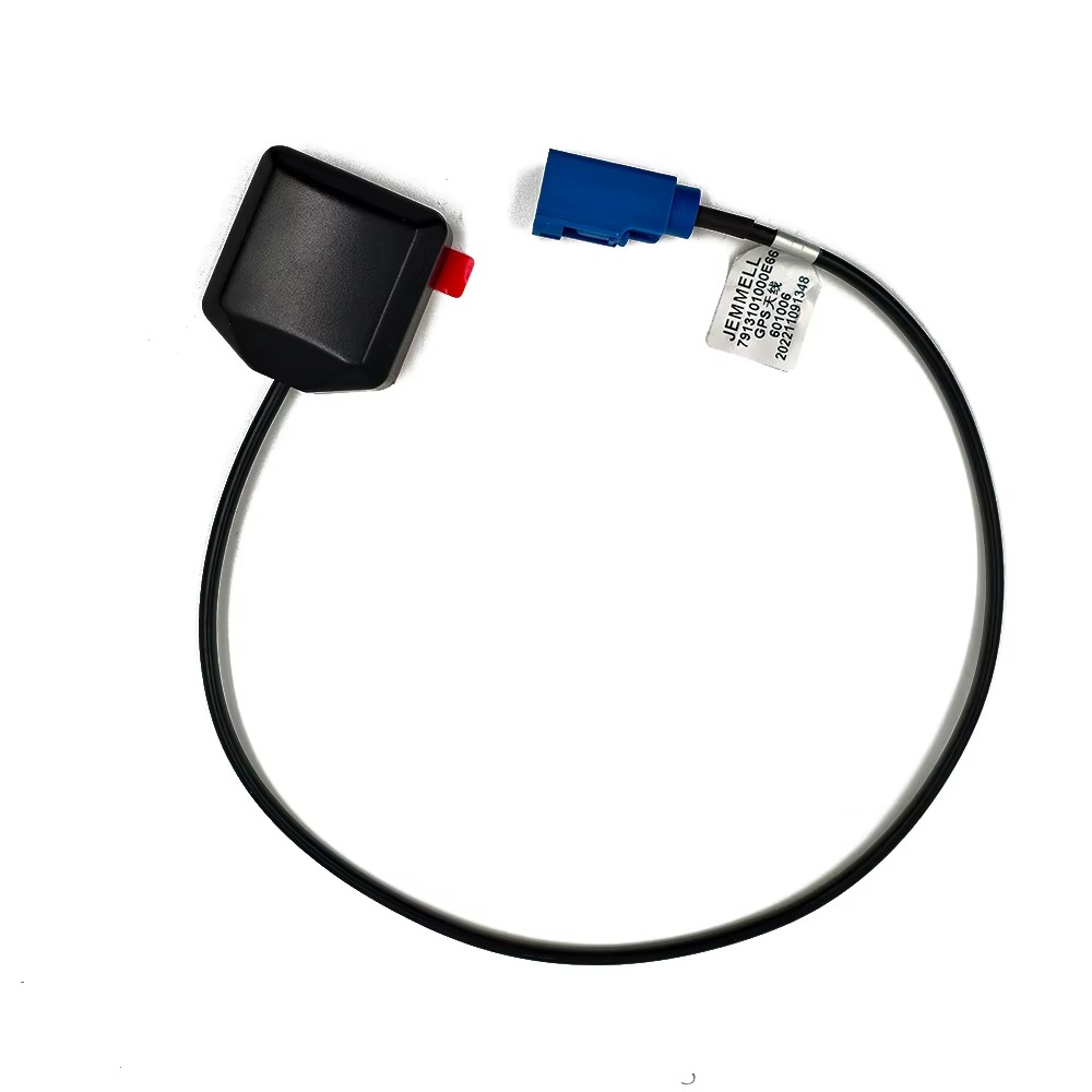

In the realm of GPS (Global Positioning System) technology, the magnetic mount GPS antenna with a 5m cable has emerged as a versatile and user-friendly solution, catering to a wide array of applications across consumer, commercial, and industrial sectors. Unlike fixed-mount GPS antennas that require permanent installation via drilling or hardware fastening, magnetic mount variants leverage a strong magnetic base to attach securely to metallic surfaces—such as the roof of a car, the hull of a small boat, or the exterior of a portable generator—eliminating the need for complex installation processes. The inclusion of a 5m cable further enhances its flexibility, allowing users to position the antenna in an optimal location for signal reception while connecting it to a GPS receiver or host device (like a navigation system, telematics unit, or portable tracker) that may be situated several meters away, such as inside a vehicle’s dashboard or a marine vessel’s cabin.
To understand the significance of this specific antenna type, it’s essential to contextualize it within the broader evolution of GPS antennas. Early GPS antennas were often bulky, fixed, and limited in mobility, designed primarily for large-scale applications like commercial shipping or aviation. As GPS technology became more accessible to consumers—driven by advancements in miniaturization, cost reduction, and signal processing—there arose a demand for antennas that could be easily installed, repositioned, and used across multiple devices. Magnetic mount antennas addressed this need by combining simplicity with functionality, while the 5m cable length was a deliberate design choice to balance two key factors: signal integrity (longer cables can introduce signal loss if not properly shielded) and practical usability (short cables restrict placement options, while excessively long cables become cumbersome to manage).
Today, magnetic mount GPS antennas with 5m cables are ubiquitous in scenarios where temporary or semi-permanent GPS connectivity is required. For example, in the automotive sector, they are used with portable navigation devices (PNDs), dashcams with GPS tracking, and fleet management systems that need to be moved between vehicles. In recreational boating, they serve as a convenient alternative to fixed marine GPS antennas for small watercraft like jet skis or fishing boats, where permanent installation may not be feasible or desired. They also find applications in industrial settings, such as tracking construction equipment, monitoring the location of delivery trucks, or providing GPS connectivity to temporary field devices like surveying tools or emergency response gear.
The market for these antennas is characterized by a diverse range of products, varying in terms of magnetic strength, cable quality, antenna gain, and environmental resistance. Entry-level models are often affordable and designed for consumer use, while high-performance variants may feature ruggedized enclosures, weatherproofing (rated for IP67 or IP68), and advanced signal filtering to withstand harsh conditions—such as extreme temperatures, rain, or dust—making them suitable for industrial or outdoor applications. Key specifications that differentiate these antennas include their operating frequency (typically tuned to the GPS L1 band at 1575.42 MHz, the primary frequency for civilian GPS use), gain (measured in dBi, with values ranging from 2 dBi for basic models to 5 dBi or higher for high-gain versions), and cable type (often RG-174 or RG-58, which are lightweight, flexible, and shielded to minimize interference).
One of the defining advantages of magnetic mount GPS antennas with 5m cables is their accessibility. Unlike fixed antennas, which may require professional installation, these antennas can be set up by anyone in a matter of minutes: simply place the magnetic base on a flat, metallic surface with a clear line of sight to the sky, route the 5m cable to the GPS receiver (taking care to avoid sharp edges that could damage the cable), and connect the two devices. This ease of use has made them a popular choice among consumers who value convenience, as well as businesses that need to deploy GPS tracking across multiple assets without incurring high installation costs.
However, it’s important to note that these antennas are not without limitations. Their performance is heavily dependent on the quality of the magnetic mount (a weak magnet can lead to the antenna dislodging during movement, such as high-speed driving or rough seas) and the cable (poor shielding can introduce electromagnetic interference, while a damaged cable can cause signal loss). Additionally, while the 5m cable offers flexibility, it may not be sufficient for large vehicles or vessels, where the distance between the optimal antenna position and the receiver could exceed 5 meters. Despite these challenges, the magnetic mount GPS antenna with a 5m cable remains a staple in the GPS ecosystem, thanks to its unique blend of versatility, affordability, and ease of use.
The design and construction of a magnetic mount GPS antenna with a 5m cable are carefully engineered to balance performance, durability, and usability. Every component—from the antenna element to the magnetic base and the 5m cable—plays a critical role in ensuring reliable GPS signal reception, secure mounting, and long-term functionality. Below is a detailed breakdown of the key components and their design considerations.
2.1 Antenna Element
At the core of the magnetic mount GPS antenna is the antenna element, responsible for capturing the weak GPS signals transmitted by satellites (typically in the L1 band at 1575.42 MHz) and converting them into electrical signals that can be processed by the GPS receiver. The most common type of antenna element used in these antennas is the patch antenna, chosen for its compact size, low profile, and excellent performance in civilian GPS applications.
A patch antenna consists of a flat, conductive patch (usually made of copper or a copper alloy) printed on a dielectric substrate (such as FR4, a fiberglass-reinforced epoxy material). The patch is designed to resonate at the GPS L1 frequency, and its size and shape are precisely calculated based on the dielectric constant of the substrate. For example, a typical patch antenna for the L1 band might have a patch size of approximately 40mm x 40mm, with a substrate thickness of 1-2mm. The patch is fed by a coaxial cable (connected to the 5m cable via a connector) that delivers the captured signal to the receiver.
One of the key design considerations for the patch element is circular polarization (CP). GPS satellites transmit signals with right-hand circular polarization (RHCP), so the antenna element must be designed to receive RHCP signals efficiently. This is achieved by shaping the patch or adding additional components (such as a ground plane) to ensure that the antenna’s polarization matches that of the satellite signals. A well-designed patch element will have a polarization match efficiency of 90% or higher, minimizing signal loss due to polarization mismatch.
Another important factor is the antenna’s gain, which measures its ability to focus energy in a specific direction. Magnetic mount GPS antennas typically have a gain ranging from 2 dBi to 5 dBi. A higher gain antenna can capture weaker signals (e.g., in urban canyons or wooded areas), but it may have a narrower beamwidth, requiring more precise positioning to maintain a clear line of sight to the satellites. Basic consumer models often have a gain of 2-3 dBi, while industrial or high-performance models may offer 4-5 dBi gain for improved performance in challenging environments.
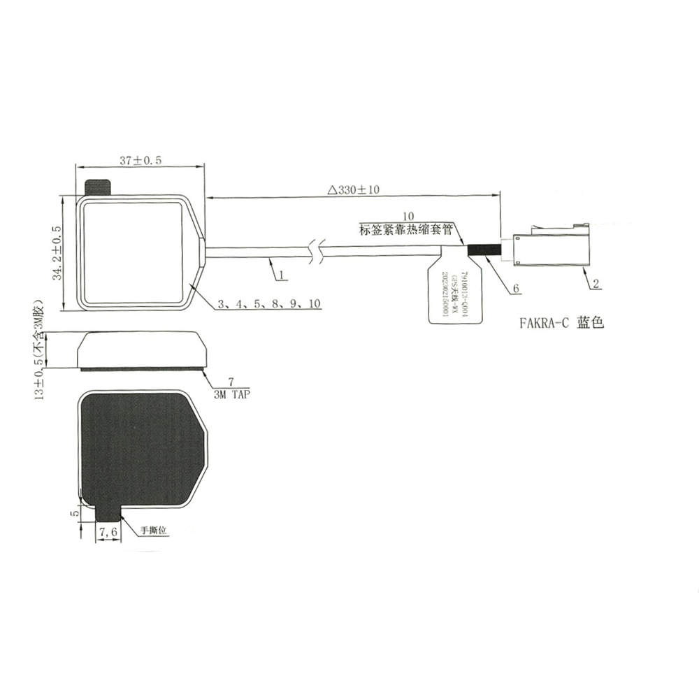
The antenna element is also enclosed in a radome, a protective cover made of a dielectric material (such as polycarbonate or ABS plastic). The radome is designed to be transparent to GPS signals (i.e., it does not absorb or reflect the signals significantly) while protecting the patch element from physical damage, dust, and moisture. The radome’s shape is often low-profile (typically 10-20mm thick) to minimize wind resistance and reduce the risk of the antenna being knocked off during movement.
2.2 Magnetic Base
The magnetic base is the defining feature of this antenna type, enabling secure attachment to metallic surfaces without the need for permanent fasteners. The design of the magnetic base must balance two key requirements: sufficient magnetic force to keep the antenna in place (even during high-speed travel or vibration) and a compact, lightweight form factor that does not add excessive bulk to the antenna.
Most magnetic bases use a neodymium magnet (also known as a rare-earth magnet), chosen for its high magnetic strength relative to its size. Neodymium magnets are made from an alloy of neodymium, iron, and boron (NdFeB) and can generate magnetic forces of 1-5 kgf (kilogram-force) for small antennas. For example, a typical magnetic mount GPS antenna might use a neodymium magnet with a diameter of 20-30mm and a thickness of 5-10mm, generating a magnetic force of 2-3 kgf—sufficient to keep the antenna attached to a vehicle roof at speeds up to 120 km/h (75 mph) or higher.
The magnet is encased in a protective housing, usually made of rubber or a soft plastic material. This housing serves two purposes: it prevents the magnet from scratching the surface of the vehicle or device to which it is attached, and it provides a non-slip grip that enhances stability. The housing is often shaped to match the radome, creating a seamless, low-profile design. Some models also include a metal plate (known as a ground plane extension) beneath the magnet, which can improve the antenna’s performance by acting as a ground plane—an essential component for patch antennas, which rely on a ground plane to radiate and receive signals efficiently.
The size and shape of the magnetic base are also optimized for usability. Most bases have a diameter of 30-50mm, making them small enough to fit in tight spaces (such as the roof of a small car) while providing enough surface area for stable attachment. The base is also designed to be flat, ensuring that it sits evenly on the metallic surface and maximizes contact with the magnet.
2.3 5m Cable
The 5m cable is a critical component of the antenna, connecting the antenna element to the GPS receiver and enabling flexible positioning. The design of the cable is carefully considered to minimize signal loss, resist interference, and withstand physical wear and tear.
The most common type of cable used in magnetic mount GPS antennas is RG-174, a lightweight, flexible coaxial cable. RG-174 has a characteristic impedance of 50 ohms (matching the impedance of most GPS receivers and antenna elements), which is essential for maximizing power transfer and minimizing signal reflection. The cable consists of several layers: a central conductor (usually made of tinned copper), an insulating dielectric (typically polyethylene), a shield (made of braided copper or aluminum foil), and an outer jacket (made of PVC or polyurethane).
The shield is a key component for reducing electromagnetic interference (EMI) and radio frequency interference (RFI). GPS signals are extremely weak (typically -130 dBm to -160 dBm at the antenna), so even small amounts of interference from nearby electronic devices (such as car radios, cell phones, or engine electronics) can degrade performance. The braided shield (with a coverage of 90% or higher) acts as a barrier, blocking external interference from reaching the central conductor and preventing the GPS signal from leaking out. Some high-performance cables also include a second foil shield (known as a dual-shield design) for enhanced interference protection.
The outer jacket of the cable is designed to be durable and resistant to environmental factors. For consumer applications, a PVC jacket is often used, as it is lightweight and cost-effective. For industrial or outdoor applications, a polyurethane jacket may be preferred, as it offers better resistance to oil, chemicals, and UV radiation, and can withstand a wider temperature range (-40°C to 85°C, compared to -20°C to 70°C for PVC).
The length of the cable—5m—is a deliberate choice based on practical usability and signal integrity. A shorter cable (e.g., 1m or 2m) would restrict the antenna’s placement, limiting the user’s ability to find a location with a clear line of sight to the sky. A longer cable (e.g., 10m or 15m) would increase flexibility but could introduce significant signal loss. RG-174 cable has a typical attenuation of 0.5 dB per meter at 1575 MHz, so a 5m cable would introduce approximately 2.5 dB of signal loss—an acceptable level that can be compensated for by the antenna’s low-noise amplifier (LNA, discussed in Section 3.2).
The cable is terminated with a connector at each end, designed to mate with the antenna element and the GPS receiver. The most common connector for the antenna end is an SMA connector (subminiature version A), a small, threaded connector that provides a secure, low-loss connection to the antenna’s LNA. The receiver end typically uses a BNC connector, a bayonet-style connector that is easy to attach and detach, or an SMA connector (depending on the receiver’s input). The connectors are plated with gold or nickel to ensure good electrical conductivity and prevent corrosion.
2.4 Additional Components
Many magnetic mount GPS antennas with 5m cables also include a low-noise amplifier (LNA) integrated into the antenna housing. The LNA is a small electronic component that amplifies the weak GPS signal captured by the antenna element before it is transmitted through the 5m cable. This is critical because the cable introduces signal loss, and the LNA helps to offset this loss, ensuring that the signal reaching the receiver is strong enough to be processed accurately.
The LNA is typically designed with a low noise figure (NF)—a measure of the noise introduced by the amplifier—of 1.5 dB or lower. A lower noise figure means that the LNA adds minimal noise to the signal, preserving the signal-to-noise ratio (SNR) which is essential for GPS receiver performance. The LNA also has a gain of 15-25 dB, which is sufficient to compensate for the 2.5 dB of cable loss (from the 5m cable) and any additional loss from connectors.
Some antennas also include a band-pass filter (BPF) integrated with the LNA. The BPF is designed to pass only the GPS L1 frequency (1575.42 MHz) while blocking signals from other frequencies (such as those used by cell phones, Wi-Fi, or radio transmitters). This further reduces interference and ensures that only the desired GPS signal is amplified and transmitted to the receiver.
The working principles of a magnetic mount GPS antenna with a 5m cable involve three key stages: capturing GPS satellite signals, processing the signals within the antenna (including amplification and filtering), and transmitting the processed signals to the GPS receiver via the 5m cable. Each stage is critical to ensuring that the receiver can accurately calculate the user’s position. Below is a detailed explanation of each stage.
3.1 GPS Satellite Signal Capture
GPS satellites orbit the Earth at an altitude of approximately 20,200 km, in six orbital planes, with each plane containing 4-5 satellites. These satellites continuously broadcast signals in the L1 band (1575.42 MHz) that contain two types of data: the Coarse/Acquisition (C/A) code, a pseudo-random noise (PRN) code used by civilian GPS receivers to identify the satellite and measure the time delay of the signal, and the Navigation (Nav) message, which contains information about the satellite’s orbit (ephemeris data), clock corrections, and system status.
The magnetic mount GPS antenna’s patch element is designed to capture these signals. For the antenna to receive signals effectively, it must have a clear line of sight to at least four GPS satellites (the minimum number required to calculate a 3D position: latitude, longitude, and altitude). The patch element resonates at the L1 frequency, meaning that when a GPS signal of 1575.42 MHz reaches the element, it induces an alternating current (AC) in the conductive patch. This AC current is proportional to the strength of the incoming signal.
The ground plane (either the metallic surface to which the antenna is mounted or the metal plate in the magnetic base) plays a crucial role in this process. The patch element and the ground plane form a resonant cavity, which enhances the antenna’s ability to capture and radiate signals. Without a ground plane, the patch antenna’s performance would be significantly degraded—signal gain would be reduced, and the antenna’s radiation pattern (the direction in which it receives signals) would become irregular.
The magnetic base ensures that the antenna is positioned correctly relative to the ground plane. By attaching the antenna to a metallic surface (such as a vehicle roof), the base ensures that the patch element is in close proximity to a large, flat ground plane, maximizing signal capture efficiency. The low-profile design of the radome also helps to minimize signal blockage, as it does not interfere with the line of sight between the patch element and the satellites.
3.2 Signal Processing within the Antenna
Once the patch element captures the GPS signal, the signal undergoes two key processing steps within the antenna: amplification by the LNA and filtering by the BPF (if included). These steps are essential to compensate for signal loss and reduce interference before the signal is transmitted through the 5m cable.
3.2.1 Low-Noise Amplification (LNA)
The GPS signal captured by the patch element is extremely weak—typically in the range of -130 dBm to -160 dBm. This is far too weak to be transmitted through the 5m cable without significant degradation, as the cable introduces approximately 2.5 dB of signal loss (as discussed in Section 2.3). The LNA addresses this by amplifying the signal by 15-25 dB, bringing the signal strength up to a level that can withstand the cable loss.
The LNA is designed with a low noise figure (NF) to ensure that it does not add excessive noise to the signal. Noise figure is a measure of how much the amplifier degrades the SNR of the signal. A typical LNA for a magnetic mount GPS antenna has an NF of 1.5 dB or lower, meaning that the noise added by the amplifier is minimal. This is critical because the SNR of the GPS signal directly affects the receiver’s ability to decode the C/A code and Nav message accurately.
The LNA is powered by the GPS receiver via the 5m cable, using a technique known as “bias tee.” The bias tee is a small circuit that separates the DC power (used to power the LNA) from the AC GPS signal. The receiver sends a DC voltage (typically 3.3V to 5V) through the central conductor of the coaxial cable. The bias tee in the antenna diverts this DC power to the LNA while allowing the AC GPS signal to pass through to the cable. This eliminates the need for a separate power cable, simplifying the antenna’s installation and reducing clutter.
3.2.2 Band-Pass Filtering (BPF)
After amplification, the signal passes through the band-pass filter (BPF) (if integrated into the antenna). The BPF is a passive electronic component that allows signals within a specific frequency range (in this case, the GPS L1 band of 1575.42 MHz ± a small tolerance, typically ±10 MHz) to pass through while attenuating signals outside this range.
This filtering step is critical for reducing interference from other electronic devices. For example, cell phones operating in the 1.8 GHz or 2.4 GHz bands, Wi-Fi routers using 2.4 GHz or 5 GHz, and FM radio transmitters (88-108 MHz) can all emit signals that might otherwise be picked up by the antenna and amplified by the LNA. These interfering signals can swamp the weak GPS signal, making it impossible for the receiver to decode the C/A code and Nav message.
A well-designed BPF for a magnetic mount GPS antenna has a high out-of-band rejection—typically 40 dB or more for frequencies outside the L1 band. This means that signals outside the L1 range are reduced in strength by 40 dB or more, effectively eliminating their impact on the GPS signal. The BPF also has a low insertion loss (less than 1 dB) within the L1 band, ensuring that the desired GPS signal is not significantly attenuated during filtering.
3.3 Signal Transmission via the 5m Cable
Once the signal has been amplified and filtered, it is transmitted from the antenna to the GPS receiver via the 5m coaxial cable. The cable’s design—with its 50-ohm impedance, braided shield, and low-loss dielectric—ensures that the signal retains its integrity during transmission.
As mentioned earlier, the 5m RG-174 cable introduces approximately 2.5 dB of signal loss at 1575 MHz. However, the LNA’s gain (15-25 dB) more than compensates for this loss. For example, if the LNA has a gain of 20 dB, the signal strength after amplification is 20 dB higher than the original captured signal. After accounting for the 2.5 dB cable loss, the signal reaching the receiver is still 17.5 dB stronger than the original signal—more than enough for the receiver to process.
The cable’s shield also plays a critical role during transmission. It blocks external EMI/RFI from entering the cable and interfering with the GPS signal, and it prevents the GPS signal from leaking out of the cable (which could cause interference with other devices). The dual-shield design (braided + foil) used in high-performance cables provides even greater protection, making the antenna suitable for use in high-interference environments like industrial facilities or busy urban areas.
The connectors at both ends of the cable ensure a secure, low-loss connection. The SMA connector at the antenna end is threaded, which creates a tight seal that minimizes signal leakage and prevents the connector from coming loose due to vibration (e.g., during driving or boating). The BNC or SMA connector at the receiver end is also designed for low insertion loss (typically less than 0.5 dB) and easy mating, allowing users to quickly connect or disconnect the antenna from the receiver.
3.4 Position Calculation by the GPS Receiver
Once the processed GPS signal reaches the receiver, the receiver performs a series of calculations to determine the user’s position. This process involves four key steps: satellite identification, time delay measurement, pseudorange calculation, and position solution.
3.4.1 Satellite Identification
The receiver first decodes the C/A code embedded in the GPS signal. Each GPS satellite transmits a unique C/A code—a 1023-bit pseudo-random sequence that repeats every 1 millisecond. The receiver has a database of all C/A codes (one for each satellite) and uses a correlator to match the received code with the stored codes. Once a match is found, the receiver identifies the satellite and knows which satellite it is receiving signals from.
3.4.2 Time Delay Measurement
The C/A code is also used to measure the time delay between when the satellite transmitted the signal and when the receiver received it. The satellite’s clock is extremely accurate (using an atomic clock), and the receiver’s clock is synchronized with the satellite’s clock via the Nav message (which contains clock correction data). The receiver measures the time it takes for the C/A code to travel from the satellite to the antenna, which is known as the “time of flight.”
3.4.3 Pseudorange Calculation
The time of flight is used to calculate the “pseudorange”—the approximate distance between the receiver and the satellite. Since the speed of light (c) is constant (approximately 300,000 km/s), the pseudorange (ρ) is calculated as ρ = c × time of flight. However, the pseudorange is not the true distance because it includes errors from several sources: atmospheric delay (ionospheric and tropospheric), satellite clock errors (even with corrections), and receiver clock errors.
3.4.4 Position Solution
To calculate a 3D position (latitude, longitude, altitude), the receiver needs pseudorange measurements from at least four satellites. This is because the receiver’s position has three unknowns (x, y, z coordinates) and the receiver’s clock error is a fourth unknown. The receiver sets up a system of four equations (one for each satellite) based on the pseudoranges and solves them simultaneously using a mathematical technique called least squares estimation.
The Nav message provides critical data for this calculation, including the satellite’s ephemeris data (which describes the satellite’s orbit in 3D space at the time the signal was transmitted) and almanac data (which provides approximate orbital information for all GPS satellites). Using the ephemeris data, the receiver calculates the satellite’s exact position in the Earth’s coordinate system (typically WGS84, the World Geodetic System 1984) at the time the signal was sent.
Once the receiver has the satellite positions and pseudoranges, it solves the system of equations to determine its own x, y, z coordinates. These coordinates are then converted to latitude, longitude, and altitude for display to the user (e.g., on a navigation device or tracking software).
The magnetic mount GPS antenna’s performance directly impacts the receiver’s ability to calculate an accurate position. A high-gain antenna with good interference rejection ensures that the receiver can capture signals from more satellites (even weak ones), leading to more pseudorange measurements and a more accurate position solution. The 5m cable’s low loss and shielding ensure that the signal reaching the receiver is strong and clean, reducing errors in the time delay and pseudorange measurements.
Magnetic mount GPS antennas with a 5m cable offer a unique set of advantages that make them ideal for many applications, but they also face inherent challenges that can limit their performance in certain scenarios. Understanding these pros and cons is essential for users to select the right antenna for their needs and for manufacturers to continue improving the technology.
4.1 Advantages
4.1.1 Easy Installation and Portability
The most significant advantage of magnetic mount GPS antennas with a 5m cable is their ease of installation. Unlike fixed-mount antennas, which require drilling holes, mounting brackets, or professional installation (costing time and money), these antennas can be installed in minutes by anyone. Users simply place the magnetic base on a flat, metallic surface (e.g., a car roof, boat hull, or equipment case) with a clear line of sight to the sky, route the 5m cable to the receiver, and connect the two devices. There is no need for specialized tools, and no damage is done to the surface the antenna is mounted on—making them ideal for rental vehicles, leased equipment, or devices where permanent installation is not allowed.
Portability is another key benefit. The lightweight design (typically 50-150 grams) and magnetic mount allow users to easily remove the antenna and reposition it on another device or vehicle. For example, a fleet manager can move a single antenna between multiple delivery trucks to track their locations, or a recreational boater can use the same antenna on a jet ski and a small fishing boat. The 5m cable enhances this portability by providing enough flexibility to position the antenna optimally on different devices, even if the receiver is located in different places (e.g., a car’s dashboard vs. a boat’s cabin).
4.1.2 Flexible Positioning for Optimal Signal Reception
GPS signal reception is heavily dependent on the antenna’s position—obstacles like buildings, trees, or vehicle roofs can block or weaken signals, leading to poor accuracy or signal loss. The magnetic mount and 5m cable give users the freedom to position the antenna in the best possible location for signal reception. For example, in a car, the antenna can be placed on the roof (the highest point with the clearest line of sight) while the receiver is mounted inside the dashboard. In a construction site, the antenna can be attached to the top of a crane (avoiding obstacles like scaffolding) while the receiver is located in a ground-based control unit.
This flexibility is particularly valuable in urban or cluttered environments. In “urban canyons” (areas with tall buildings), GPS signals are often blocked or reflected (causing multipath interference). By moving the magnetic mount antenna to a higher position (e.g., the top of a vehicle’s roof rack) or a location with fewer obstacles, users can significantly improve signal strength and reduce interference. The 5m cable ensures that even if the optimal position is several meters away from the receiver, the antenna can still be connected without signal loss.
4.1.3 Cost-Effectiveness
Magnetic mount GPS antennas with a 5m cable are generally more cost-effective than fixed-mount or high-performance antennas. Entry-level models for consumer use typically cost between \(20 and \)50, while high-performance industrial models (with ruggedization and advanced filtering) range from \(80 to \)200. This is significantly less than fixed-mount marine or aviation antennas, which can cost several hundred dollars, or professional surveying antennas, which can cost thousands.
The cost savings extend beyond the initial purchase price. Since these antennas do not require professional installation, users save on installation fees (which can range from \(50 to \)200 for fixed-mount antennas). Additionally, their portability means that users do not need to purchase a separate antenna for each device or vehicle—one antenna can be shared across multiple assets, reducing overall costs for businesses and consumers alike.
4.1.4 Compatibility with a Wide Range of Devices
Magnetic mount GPS antennas with a 5m cable are designed to be compatible with most civilian GPS receivers, thanks to their standard connectors (SMA, BNC) and 50-ohm impedance. This compatibility makes them a versatile solution for a wide range of devices, including:
Portable navigation devices (PNDs) from brands like Garmin, TomTom, and Magellan.
Dashcams with GPS tracking (e.g., Xiaomi, BlackVue, Viofo).
Fleet management systems (e.g., Verizon Connect, Geotab).
Marine navigation devices for small boats (e.g., Lowrance, Humminbird).
Industrial tracking devices (e.g., for construction equipment, shipping containers).
Emergency response gear (e.g., portable GPS units used by search and rescue teams).
Many antennas also support multi-constellation reception (e.g., GPS + GLONASS, GPS + Galileo) in addition to GPS, making them compatible with receivers that use multiple satellite systems for improved accuracy and signal availability. This broad compatibility ensures that users can easily upgrade their existing GPS devices with a magnetic mount antenna without needing to replace the entire system.
4.1.5 Durability for Everyday Use
While not all magnetic mount GPS antennas are ruggedized, most are designed to withstand the rigors of everyday use. The radome (made of polycarbonate or ABS plastic) protects the antenna element from scratches, impacts, and minor moisture exposure. The magnetic base’s rubber housing prevents damage to the mounting surface and provides a secure grip even during vibration (e.g., while driving on rough roads). The 5m cable’s outer jacket (PVC or polyurethane) is resistant to wear and tear, and the connectors are plated to prevent corrosion.
For more demanding environments, high-performance models offer additional durability features. These include IP67 or IP68 weatherproof ratings (protecting against dust, rain, and temporary submersion), UV resistance (preventing degradation from sunlight), and wide temperature ranges (typically -40°C to 85°C). These features make ruggedized magnetic mount antennas suitable for outdoor applications like construction, mining, or marine use, where the antenna may be exposed to harsh conditions.
4.2 Challenges
4.2.1 Reliance on Metallic Mounting Surfaces
The magnetic mount is both a strength and a weakness of these antennas—it requires a metallic surface to attach to, limiting their use on non-metallic devices or vehicles. For example, if a user has a plastic-bodied drone, a fiberglass boat, or a wooden recreational vehicle (RV), the magnetic base will not adhere, making the antenna unusable. In such cases, users must either use a fixed-mount antenna (requiring drilling) or a adhesive-mount antenna (which may damage the surface).
Even on metallic surfaces, the quality of the mounting surface can affect performance. The surface must be flat and smooth to ensure maximum contact between the magnetic base and the metal—curved or uneven surfaces (e.g., a vehicle’s fender) can reduce the magnetic grip, increasing the risk of the antenna dislodging during movement. Additionally, the surface must be ferromagnetic (e.g., steel, iron)—non-ferromagnetic metals like aluminum or copper will not attract the neodymium magnet, making the antenna impossible to mount.
4.2.2 Risk of Dislodgment at High Speeds or in Rough Conditions
While the magnetic base provides sufficient grip for most everyday scenarios (e.g., driving at highway speeds), it can dislodge in extreme conditions. For example, if the antenna is mounted on a vehicle traveling at high speeds (over 120 km/h or 75 mph) or in strong winds (e.g., on a boat in rough seas), the aerodynamic forces or vibration can overcome the magnetic force, causing the antenna to fall off. This not only results in lost GPS signal but also poses a safety hazard—if the antenna falls off a moving vehicle, it could hit another vehicle or pedestrian.
The risk of dislodgment is higher with low-quality antennas that use weak magnets (with a magnetic force of less than 1 kgf). Even high-quality antennas with 3-5 kgf magnets can dislodge if the mounting surface is dirty, oily, or covered in debris (which reduces friction between the rubber housing and the surface). Users must therefore ensure that the mounting surface is clean and dry before installing the antenna, and avoid using the antenna in extreme speed or wind conditions unless it is specifically rated for such use.
4.2.3 Signal Loss and Interference in Challenging Environments
While magnetic mount GPS antennas with 5m cables perform well in open areas, they can struggle in challenging environments where signal reception is poor. One common issue is multipath interference—this occurs when GPS signals bounce off surfaces like buildings, trees, or water before reaching the antenna. The reflected signals arrive at the antenna slightly later than the direct signals, causing errors in the pseudorange measurements and reducing position accuracy.
Multipath interference is particularly problematic in urban canyons, dense forests, or near large bodies of water. The low-profile design of the antenna (which is beneficial for aerodynamics) can also exacerbate this issue, as it may not be tall enough to avoid reflections from nearby obstacles. While some antennas include multipath mitigation features (e.g., advanced filtering or ground plane extensions), these are not as effective as the features found in high-performance fixed-mount antennas.
Another challenge is signal blockage. If the antenna is mounted in a location with partial or complete blockage of the sky (e.g., under a bridge, in a parking garage, or inside a building), it will not be able to receive signals from enough satellites to calculate a position. The 5m cable allows users to reposition the antenna to a clearer location, but in some cases (e.g., a deep underground parking garage), there may be no viable location for signal reception.
4.2.4 Cable Limitations: Length and Durability
The 5m cable is a balance between flexibility and signal integrity, but it has inherent limitations. For users with large vehicles or devices (e.g., a semi-truck, a large boat, or an industrial crane), the 5m cable may be too short to reach the optimal antenna position. In such cases, users may need to use a cable extension, but this introduces additional signal loss (each meter of extension cable adds approximately 0.5 dB of loss) and increases the risk of interference.
The cable’s durability is another concern. While the outer jacket is resistant to wear and tear, it can be damaged by sharp edges (e.g., a vehicle’s door frame, a boat’s hull) or excessive bending. A damaged cable can cause signal loss or allow interference to enter, degrading the antenna’s performance. The connectors are also vulnerable to damage—if the connector is bent or the pins are broken, the antenna will not work. Users must therefore take care when routing the cable to avoid sharp edges and ensure that the connectors are not mishandled.
4.2.5 Limited Performance in High-Interference Environments
Despite the cable’s shielding and the antenna’s BPF, magnetic mount GPS antennas can still be affected by strong electromagnetic interference (EMI) or radio frequency interference (RFI). This is particularly true in industrial environments, where heavy machinery (e.g., motors, welders, or generators) emits strong EMI, or in busy urban areas, where there are many wireless devices (e.g., cell phones, Wi-Fi routers, or radio transmitters) operating in nearby frequency bands.
Strong EMI can saturate the LNA, causing it to distort the GPS signal or shut down entirely.This saturation occurs when the EMI signal is so strong that it exceeds the LNA’s linear operating range, causing the amplifier to produce non-linear distortions. These distortions can mask the weak GPS signal, making it impossible for the receiver to decode the C/A code. In extreme cases, strong EMI can even damage the LNA, rendering the antenna inoperable.
Radio frequency interference (RFI) from nearby wireless devices is another issue. For example, a 4G LTE cell tower operating in the 1.7-2.1 GHz band or a 5G base station using the 3.5 GHz band can emit signals that are close to the GPS L1 band (1575.42 MHz). While the BPF is designed to block these signals, it may not be able to completely attenuate extremely strong RFI signals. This can lead to “desense” (desensitization) of the receiver, where the receiver’s ability to detect weak GPS signals is reduced, even if the RFI signal is not strong enough to saturate the LNA.
High-interference environments also pose challenges for the cable’s shielding. While braided shields provide good protection against low-frequency EMI, they are less effective at blocking high-frequency RFI (above 1 GHz). Dual-shield (braided + foil) cables offer better high-frequency protection, but they are more expensive and less flexible than single-shield cables. Many entry-level magnetic mount GPS antennas use single-shield cables to keep costs low, making them vulnerable to high-frequency RFI in busy urban or industrial areas.
5.1 Current Applications
Magnetic mount GPS antennas with a 5m cable have found widespread use across consumer, commercial, and industrial sectors, thanks to their ease of installation, portability, and cost-effectiveness. Below are the key application areas, along with specific use cases and benefits.
5.1.1 Consumer Automotive: Dashcams and Portable Navigation
The consumer automotive sector is one of the largest markets for magnetic mount GPS antennas with a 5m cable, primarily driven by the popularity of dashcams and portable navigation devices (PNDs).
Dashcams with GPS tracking use these antennas to record the vehicle’s location, speed, and route alongside video footage. This data is critical for insurance claims (to prove fault in accidents), fleet monitoring (for rental car companies), and personal safety (to track the vehicle if it is stolen). The magnetic mount allows users to install the antenna on the car roof—where signal reception is optimal—while the 5m cable routes to the dashcam inside the vehicle. For example, a BlackVue DR900X dashcam user can attach the antenna to the roof, route the cable through the car’s door seal, and connect it to the dashcam, ensuring reliable GPS tracking without drilling holes.
Portable navigation devices (PNDs) from brands like Garmin and TomTom also rely on these antennas for improved signal reception. Many PNDs have built-in antennas, but these are often low-gain and prone to signal blockage by the vehicle’s dashboard or windshield. Adding a magnetic mount antenna with a 5m cable allows users to position the antenna outside the vehicle, significantly improving signal strength and accuracy. This is particularly useful in urban canyons or rural areas with limited satellite visibility, where a built-in antenna may struggle to maintain a connection.
5.1.2 Fleet Management and Commercial Transportation
Fleet management companies use magnetic mount GPS antennas with a 5m cable to track the location, speed, and route of delivery trucks, taxis, and service vehicles. Unlike fixed-mount antennas, which are permanently installed on a single vehicle, these antennas can be easily moved between vehicles—making them ideal for fleets with temporary or leased vehicles.
For example, a small delivery company with 10 trucks may only need 5 antennas, as each antenna can be transferred from a truck that is not in use to one that is. The 5m cable allows the antenna to be mounted on the truck roof (for optimal signal) while the GPS tracker is installed inside the cab, connected to the vehicle’s OBD-II port for power. Fleet managers can use the GPS data to optimize routes, reduce fuel costs, and ensure drivers adhere to schedules. The portability of the antenna also simplifies maintenance—if a tracker needs to be repaired, the antenna can be quickly disconnected and reused on another tracker.
In commercial transportation, these antennas are also used in refrigerated trucks to track the location of perishable goods. The antenna’s durability (e.g., IP67 weatherproofing) ensures it can withstand outdoor conditions, while the 5m cable allows the tracker to be mounted inside the refrigerated compartment (away from the antenna, which is on the roof).
5.1.3 Recreational Marine and Boating
For small recreational boats (e.g., fishing boats, jet skis, and pontoons), magnetic mount GPS antennas with a 5m cable are a cost-effective alternative to fixed-mount marine GPS antennas. Fixed-mount marine antennas require drilling holes in the boat’s hull or deck, which can be damaging and time-consuming—especially for fiberglass boats (though the magnetic mount is limited to metallic parts of the boat, such as a steel railing or engine compartment cover).
Recreational boaters use these antennas with marine navigation devices (e.g., Lowrance HOOK Reveal) to track their position, mark fishing spots, and navigate back to shore. The 5m cable allows the antenna to be mounted on a high point of the boat (e.g., a railing or T-top) for clear sky visibility, while the navigation device is mounted at the helm. For example, a fishing boat owner can attach the antenna to the T-top, route the cable down to the helm, and connect it to the navigation device—ensuring accurate positioning even in open water.
Ruggedized models with IP68 weatherproofing are particularly popular in this sector, as they can withstand exposure to saltwater, rain, and UV radiation. The magnetic mount also makes it easy to remove the antenna when the boat is not in use, preventing theft or damage.
5.1.4 Industrial and Construction Equipment Tracking
In the industrial sector, magnetic mount GPS antennas with a 5m cable are used to track the location and usage of construction equipment (e.g., excavators, bulldozers, and cranes), mining vehicles, and generators. These assets are often moved between job sites, so the antenna’s portability is a key advantage—one antenna can be used to track multiple pieces of equipment.
For example, a construction company with a fleet of excavators can attach an antenna to each excavator’s steel cab roof when it is deployed to a job site. The 5m cable connects to a GPS tracker installed inside the cab, which sends location data to a central management system. This data allows the company to monitor equipment utilization, prevent theft, and ensure equipment is deployed to the right job site. The antenna’s durability is also critical here—ruggedized models can withstand dust, vibration, and extreme temperatures (e.g., -40°C to 85°C), which are common in construction and mining environments.
These antennas are also used in temporary industrial setups, such as mobile power generators for outdoor events or disaster relief. The magnetic mount allows the antenna to be attached to the generator’s steel frame, while the 5m cable connects to a tracker that monitors the generator’s location and fuel level.
5.1.5 Emergency Response and Search and Rescue
Emergency response teams (e.g., fire departments, paramedics, and search and rescue [SAR] teams) use magnetic mount GPS antennas with a 5m cable to track the location of emergency vehicles and personnel in the field. These antennas are ideal for emergency situations because they can be quickly installed on any metallic vehicle (e.g., a fire truck, ambulance, or SAR boat) without tools.
For example, a SAR team responding to a missing hiker in a remote forest can attach the antenna to their vehicle’s roof, connect it to a portable GPS tracker, and use the data to navigate to the search area. The 5m cable allows the tracker to be operated inside the vehicle, while the antenna is mounted outside for clear signal reception. In urban emergency situations (e.g., a building collapse), the antenna can be attached to a drone (if the drone has a metallic frame) to provide aerial GPS tracking of the disaster site.
The portability of these antennas also makes them useful for temporary command centers. Emergency teams can set up a command center in a vehicle or tent, attach the antenna to a nearby metallic structure (e.g., a fence or utility pole), and use the GPS data to coordinate response efforts.
5.2 Future Trends
The future of magnetic mount GPS antennas with a 5m cable is shaped by advancements in satellite technology, materials science, and user demand for improved performance and versatility. Below are the key trends that will drive innovation in this space over the next 5-10 years.
5.2.1 Multi-Constellation and Multi-Frequency Support
As global satellite navigation systems (GNSS) continue to expand, future magnetic mount GPS antennas will increasingly support multi-constellation reception (e.g., GPS + GLONASS + Galileo + BeiDou) and multi-frequency operation (e.g., L1 + L5 for GPS, E1 + E5 for Galileo).
Multi-constellation support increases the number of satellites available for positioning, improving signal availability in challenging environments (e.g., urban canyons, dense forests). For example, a multi-constellation antenna can receive signals from 10-15 satellites (compared to 4-6 for a GPS-only antenna), leading to more accurate and reliable position calculations. Multi-frequency support further enhances performance by reducing errors caused by atmospheric delay (ionospheric and tropospheric). The L5 frequency (1176.45 MHz for GPS) is less affected by ionospheric delay than the L1 frequency, so a dual-frequency (L1/L5) antenna can achieve position accuracy of 1-3 meters (compared to 5-10 meters for L1-only antennas).
Manufacturers are already starting to release multi-constellation/multi-frequency magnetic mount antennas for consumer and commercial use. For example, Garmin’s GTU 10 tracker antenna supports GPS, GLONASS, and Galileo, while high-performance models from Trimble support L1/L5 frequencies. In the future, these features will become standard in mid-range and entry-level antennas as component costs decrease.
5.2.2 Improved Magnetic Mount Design for Non-Metallic Surfaces
To address the limitation of relying on metallic surfaces, manufacturers will develop innovative magnetic mount designs that can attach to non-metallic surfaces (e.g., fiberglass boats, plastic drones, wooden RVs). One approach is to integrate a removable adhesive pad with the magnetic base—users can use the magnetic mount on metallic surfaces or switch to the adhesive pad for non-metallic surfaces. The adhesive pad would be reusable (using a silicone-based adhesive) to avoid damaging the mounting surface.
Another approach is to use a “magnetic plate” system. The user attaches a thin, ferromagnetic plate to the non-metallic surface (using adhesive or screws), and the antenna’s magnetic base attaches to the plate. This system allows the antenna to be used on any surface, while retaining the portability of the magnetic mount. For example, a drone manufacturer could include a ferromagnetic plate with their plastic-bodied drone, allowing users to attach a magnetic mount GPS antenna for improved positioning.
These designs will expand the application range of magnetic mount GPS antennas, making them suitable for non-metallic devices that were previously incompatible.
5.2.3 Enhanced Ruggedization for Extreme Environments
As demand for magnetic mount GPS antennas grows in industrial, marine, and outdoor applications, manufacturers will focus on enhancing ruggedization to withstand even harsher conditions. Key improvements will include:
Higher Weatherproof Ratings: Moving beyond IP68 to IP69K, which provides protection against high-pressure, high-temperature water jets (critical for industrial cleaning or marine applications where the antenna may be exposed to heavy rain or saltwater spray).
Increased Chemical Resistance: Using materials like PTFE (polytetrafluoroethylene) for the cable jacket and radome to resist corrosion from chemicals, oils, and solvents—making the antenna suitable for mining, oil and gas, and chemical processing environments.
Shock and Vibration Resistance: Incorporating shock-absorbing materials (e.g., silicone gaskets) into the magnetic base and radome to withstand extreme vibration (e.g., from heavy machinery) or impacts (e.g., from falling debris on a construction site).
These ruggedization features will make magnetic mount GPS antennas a viable alternative to expensive industrial fixed-mount antennas in extreme environments.
5.2.4 Integration with Wireless Technologies (5G and Wi-Fi)
Future magnetic mount GPS antennas will integrate with wireless technologies like 5G and Wi-Fi to enable real-time data transmission and remote management. For example, an antenna could include a 5G module that sends GPS position data directly to a cloud-based management platform, eliminating the need for a separate GPS tracker. This integration would simplify installation (one device instead of two) and reduce costs for users.
Wi-Fi integration would allow users to configure and monitor the antenna via a smartphone app. For example, a fleet manager could use a Wi-Fi-connected antenna to check signal strength, update firmware, or adjust settings (e.g., filter parameters) remotely—without needing to physically access the antenna. This remote management capability would save time and improve efficiency, especially for fleets with assets spread across multiple locations.
These wireless integrations will align magnetic mount GPS antennas with the trend toward “smart” IoT (Internet of Things) devices, making them more versatile and user-friendly.
5.2.5 Miniaturization and Reduced Power Consumption
Advancements in materials science and electronic components will lead to smaller, lighter magnetic mount GPS antennas with reduced power consumption. Miniaturization will be driven by the use of micro-patch antenna elements (smaller than 30mm x 30mm) and integrated circuits (ICs) that combine the LNA, BPF, and bias tee into a single chip. These smaller antennas will be ideal for compact devices like drones, portable trackers, and wearable technology (e.g., GPS-enabled safety vests for construction workers).
Reduced power consumption will be achieved through the use of low-power LNAs and energy-efficient bias tees. This will extend the battery life of portable GPS devices, making them more useful for outdoor applications like hiking or camping, where access to power is limited. For example, a portable GPS tracker with a low-power magnetic mount antenna could operate for up to 6 months on a single battery charge, compared to 1-2 months with current antennas.
Conclusion
Magnetic mount GPS antennas with a 5m cable have established themselves as a versatile, cost-effective, and user-friendly solution for GPS positioning across consumer, commercial, and industrial applications. Their unique combination of easy installation (no drilling or professional tools required), portability (can be moved between devices), and flexible positioning (5m cable enables optimal signal placement) has made them a preferred choice for users ranging from recreational boaters to fleet managers.
In terms of design and construction, these antennas are engineered to balance performance and practicality. The patch antenna element, with its circular polarization and optimized gain, ensures efficient capture of GPS L1 signals, while the neodymium magnetic base provides secure attachment to metallic surfaces. The 5m coaxial cable—with its low loss, shielding, and standard connectors—enables reliable signal transmission to the GPS receiver, while the integrated LNA and BPF compensate for cable loss and reduce interference.
The working principles of these antennas, from signal capture and processing to position calculation, highlight their dependence on a clear line of sight to GPS satellites and the quality of their components. A well-designed antenna with a high-gain element, low-noise LNA, and effective filtering can significantly improve the accuracy and reliability of GPS positioning, even in moderately challenging environments.
While these antennas offer numerous advantages—including ease of use, cost-effectiveness, and compatibility with a wide range of devices—they also face inherent challenges. Their reliance on metallic mounting surfaces limits use on non-metallic devices, and the magnetic base can dislodge in high-speed or rough conditions. Additionally, they may struggle with signal loss, multipath interference, and strong EMI/RFI in extreme environments, and the 5m cable may be too short for large vehicles or equipment.
Looking ahead, the future of magnetic mount GPS antennas with a 5m cable is promising, driven by trends like multi-constellation/multi-frequency support, improved mount designs for non-metallic surfaces, enhanced ruggedization, wireless integration (5G/Wi-Fi), and miniaturization. These advancements will address current limitations, expand application areas, and make these antennas even more valuable for users in a wide range of sectors.
In conclusion, magnetic mount GPS antennas with a 5m cable have become an indispensable tool in the GPS ecosystem, bridging the gap between fixed-mount antennas (which are durable but inflexible) and built-in antennas (which are convenient but low-performance). As technology continues to evolve, these antennas will play an even more critical role in enabling accurate, reliable GPS positioning for consumer, commercial, and industrial users alike. Whether used to track a delivery truck, navigate a fishing boat, or coordinate an emergency response, magnetic mount GPS antennas with a 5m cable will remain a key solution for years to come.

 86 0755 2819 9597
Lucy Yang | lucy.y@toxutech.com
Nicole Li | nicole@toxutech.com
Dotty Zhao | sales04@toxutech.com
Global Business Director / Sales Team / Global Operations


 En
En Cn
Cn Korean
 Home >


