Combo Antenna Combo Antenna

Language
Built-in RTK GPS Antenna
GNSS Car Antenna
GNSS Car Antenna

GPS & GNSS Antenna

Home >  GPS & GNSS Antenna > 

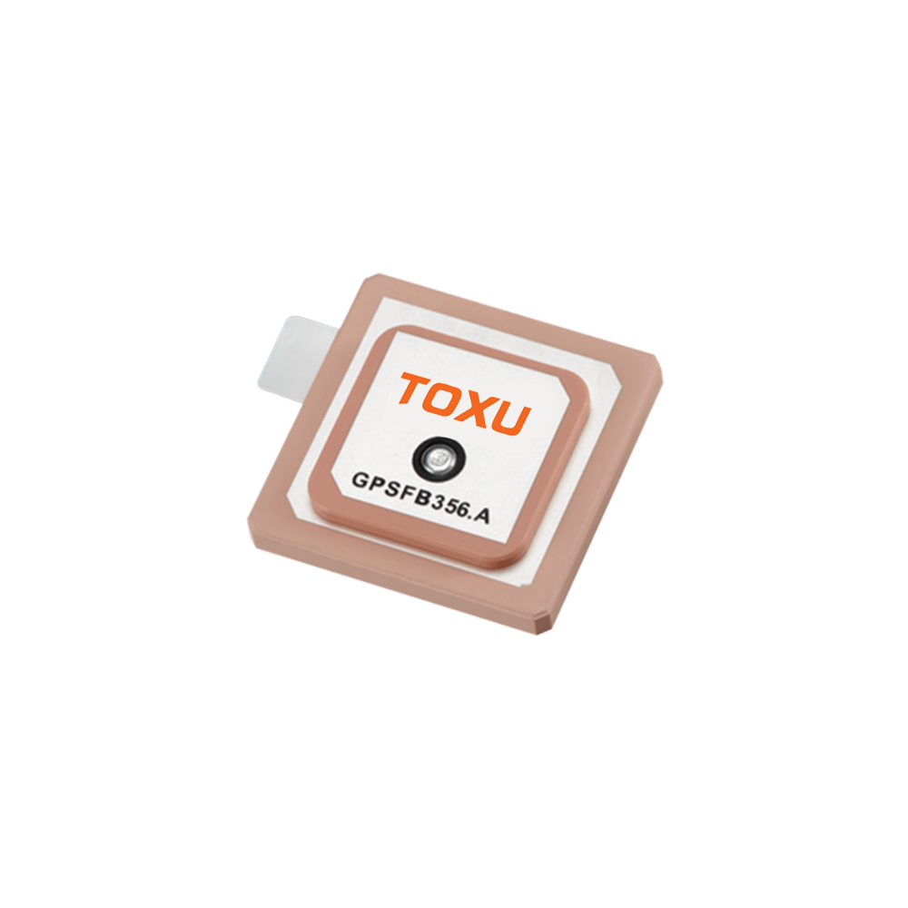
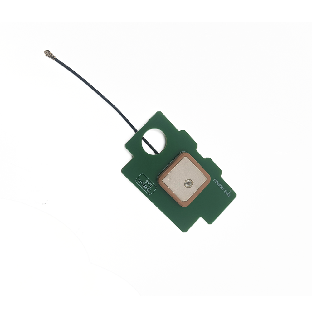
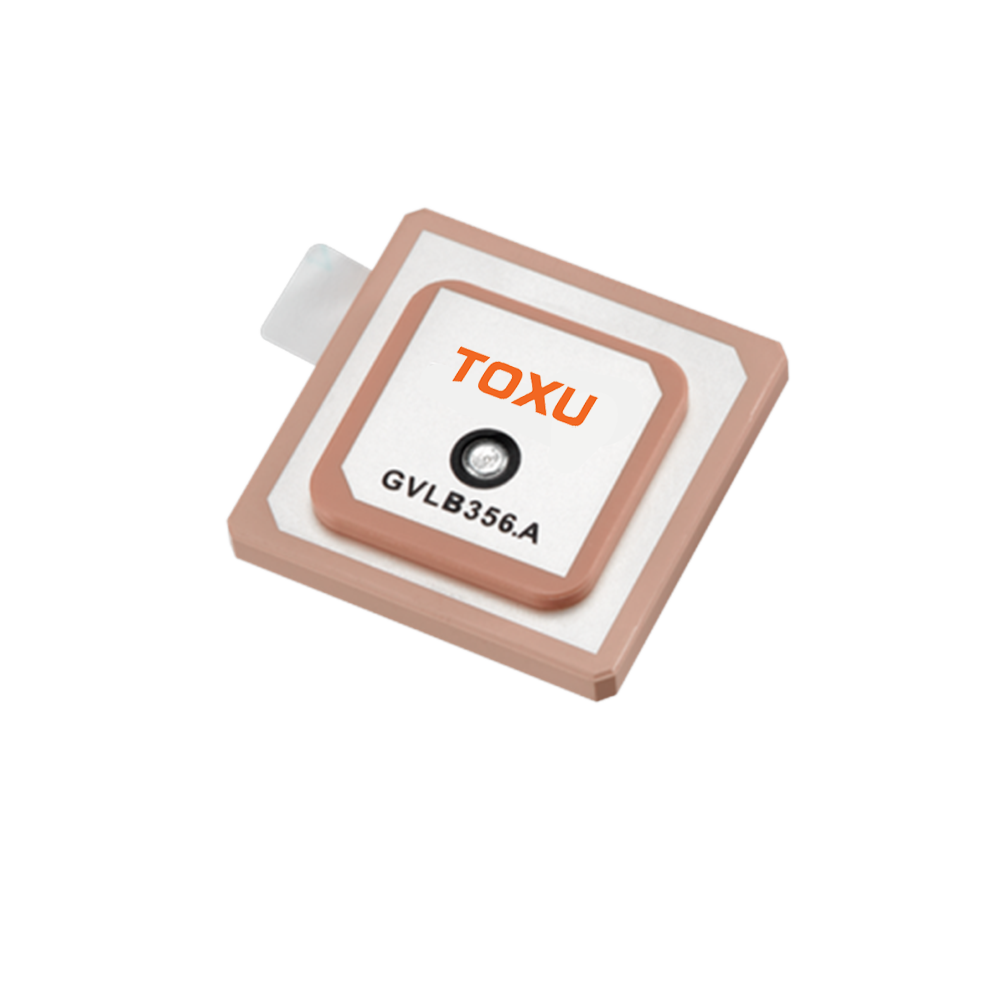
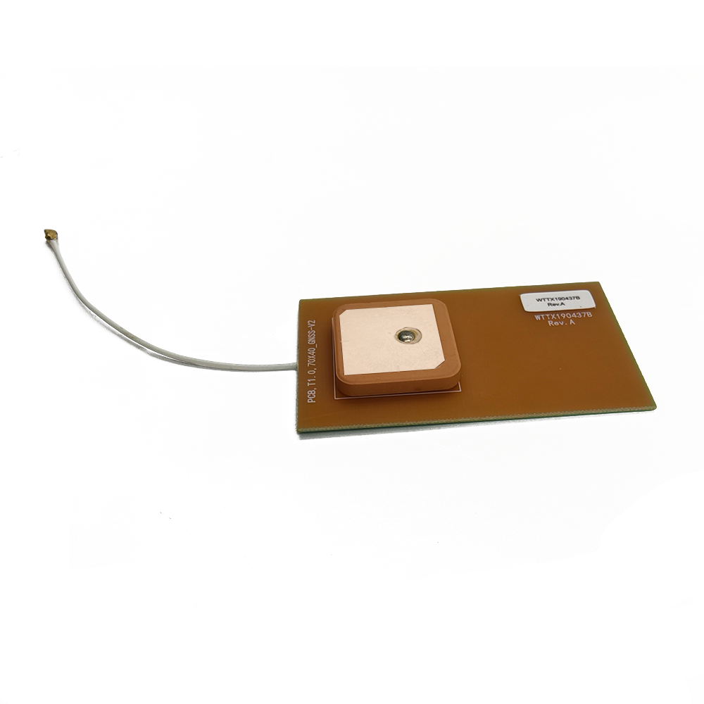
Low-profile custom GNSS patch antenna

Global Navigation Satellite Systems (GNSS) have become an integral part of modern life, enabling precise positioning, navigation, and timing (PNT) across various applications, from consumer electronics to military and aerospace systems. Among the different types of antennas used for GNSS reception, low-profile custom patch antennas have gained significant popularity due to their compact size, ease of integration, and cost-effectiveness. This article provides an overview of low-profile custom GNSS patch antennas, covering their basic definition, historical development, and key characteristics.


Leave a message Contact

Fill in your email address

Or you can continue to download without filling in

Overview

A GNSS patch antenna is a type of microstrip antenna designed to receive signals from GNSS satellites, which operate in the L-band (typically around 1.2 GHz for GPS and 1.5 GHz for Galileo). The term "low-profile" refers to the antenna's thin and flat structure, which makes it suitable for applications where space is limited. Custom patch antennas are tailored to meet specific requirements, such as frequency bands, radiation patterns, and polarization, ensuring optimal performance in a given application.

Historical Development

The development of GNSS patch antennas can be traced back to the early days of GPS technology in the 1980s. Initially, GNSS receivers relied on bulky helical or quadrifilar helix antennas, which were not suitable for portable devices. The introduction of microstrip patch antennas in the 1990s revolutionized GNSS receiver design, enabling the development of compact and lightweight devices. Over the years, advancements in materials science, manufacturing techniques, and simulation tools have further refined the design and performance of low-profile custom GNSS patch antennas.

Key Characteristics

Low-profile custom GNSS patch antennas exhibit several key characteristics that make them ideal for a wide range of applications:

Compact Size: The thin and flat structure of patch antennas allows for easy integration into devices with limited space, such as smartphones, tablets, and wearable devices.

Low Cost: Patch antennas are relatively inexpensive to manufacture, making them a cost-effective solution for mass-produced consumer electronics.

Customizability: Custom patch antennas can be designed to meet specific frequency bands, radiation patterns, and polarization requirements, ensuring optimal performance in a given application.

Ease of Integration: Patch antennas can be easily integrated with other electronic components, such as RF front-ends and processors, simplifying the overall system design.

Robustness: The solid construction of patch antennas makes them resistant to mechanical stress and environmental factors, ensuring reliable performance in harsh conditions.


Design and Construction

Designing and constructing a low-profile custom GNSS patch antenna requires a deep understanding of antenna theory, electromagnetic principles, and manufacturing techniques. This article delves into the key aspects of designing and constructing these antennas, covering materials selection, antenna geometry, feeding mechanisms, and manufacturing processes.

Materials Selection

The choice of materials plays a crucial role in determining the performance of a GNSS patch antenna. The substrate material, which forms the base of the antenna, should have a low dielectric constant and low loss tangent to minimize signal attenuation. Common substrate materials include FR4 (a type of fiberglass-reinforced epoxy laminate), Rogers materials (such as RO4003C and RO4350B), and ceramic-filled PTFE composites. The conductive layer, typically made of copper, is used to form the patch and ground plane. The thickness of the conductive layer affects the antenna's impedance and radiation efficiency.

Antenna Geometry

The geometry of a GNSS patch antenna is determined by its intended frequency band and radiation pattern. The most common shape for a patch antenna is rectangular, although circular and square patches are also used. The dimensions of the patch are calculated based on the desired resonant frequency and the substrate's dielectric constant. To achieve multi-band operation, techniques such as slot loading, fractal geometry, and stacked patches can be employed. These techniques allow the antenna to resonate at multiple frequencies, enabling reception of signals from different GNSS constellations.

Feeding Mechanisms

The feeding mechanism is responsible for transferring RF energy from the transmission line to the patch antenna. Common feeding techniques include microstrip line feeding, coaxial probe feeding, and aperture coupling. Microstrip line feeding is the simplest and most widely used method, where the microstrip line is directly connected to the edge of the patch. Coaxial probe feeding involves inserting a coaxial probe through the substrate to feed the patch, providing better impedance matching and isolation. Aperture coupling uses a slot in the ground plane to couple energy from a microstrip line to the patch, offering improved bandwidth and radiation efficiency.

Manufacturing Processes

The manufacturing process of a low-profile custom GNSS patch antenna involves several steps, including substrate preparation, conductive layer deposition, patterning, and assembly. The substrate is first cleaned and prepared to ensure good adhesion of the conductive layer. The conductive layer is then deposited using techniques such as sputtering, electroplating, or chemical vapor deposition. The patch and ground plane patterns are defined using photolithography or laser ablation. Finally, the antenna is assembled by attaching the feeding mechanism and any additional components, such as matching networks or filters.

Simulation and Optimization

Simulation tools play a vital role in the design and optimization of GNSS patch antennas. Electromagnetic simulation software, such as HFSS (High-Frequency Structure Simulator) and CST Microwave Studio, allows designers to model the antenna's performance, including its radiation pattern, impedance matching, and bandwidth. By iteratively adjusting the antenna's geometry and materials, designers can optimize its performance to meet specific requirements. Prototyping and testing are also essential steps in the design process, allowing designers to validate the simulation results and make any necessary adjustments.


Working Principles

Understanding the working principles of low-profile custom GNSS patch antennas is essential for designing and optimizing their performance. This article explains the fundamental concepts behind patch antenna operation, including resonance, radiation patterns, polarization, and impedance matching.

Resonance

A GNSS patch antenna operates by resonating at a specific frequency, which corresponds to the wavelength of the GNSS signals it is designed to receive. The resonant frequency of a patch antenna is determined by its physical dimensions and the substrate's dielectric constant. When the antenna is excited at its resonant frequency, a standing wave is established between the patch and the ground plane, resulting in efficient radiation of electromagnetic energy. The quality factor (Q) of the antenna, which is a measure of its bandwidth, is influenced by factors such as the substrate's loss tangent and the antenna's radiation efficiency.

Radiation Patterns

The radiation pattern of a GNSS patch antenna describes how the antenna radiates energy in different directions. Patch antennas typically exhibit a broadside radiation pattern, where the maximum radiation occurs perpendicular to the plane of the patch. The shape of the radiation pattern can be controlled by adjusting the antenna's geometry, such as the size and shape of the patch, the presence of slots or fractal elements, and the use of multiple patches in an array configuration. The radiation pattern is crucial for ensuring that the antenna can receive signals from GNSS satellites located at different elevations and azimuth angles.

Polarization

Polarization refers to the orientation of the electric field vector of the radiated electromagnetic wave. GNSS patch antennas are typically designed to be right-hand circularly polarized (RHCP) or left-hand circularly polarized (LHCP), depending on the polarization of the GNSS signals. Circular polarization is preferred over linear polarization because it is less sensitive to the orientation of the antenna relative to the satellite, reducing signal fading due to multipath propagation. The polarization of a patch antenna can be controlled by adjusting the shape and orientation of the patch and the feeding mechanism.

Impedance Matching

Impedance matching is essential for ensuring efficient transfer of RF energy between the antenna and the transmission line. The input impedance of a GNSS patch antenna is determined by its geometry and the substrate's properties. To achieve impedance matching, the antenna's input impedance should be equal to the characteristic impedance of the transmission line (typically 50 ohms). Matching networks, such as quarter-wave transformers, LC circuits, or microstrip stubs, can be used to match the antenna's impedance to the transmission line. Proper impedance matching minimizes signal reflections and maximizes the antenna's radiation efficiency.

Multi-Path and Interference Mitigation

GNSS patch antennas are susceptible to multi-path propagation, where signals from the satellite reflect off nearby objects before reaching the antenna, causing signal fading and errors in positioning. To mitigate multi-path effects, techniques such as using a ground plane with a specific shape or size, employing multiple antennas in a diversity configuration, or using advanced signal processing algorithms can be employed. Interference from other RF sources, such as cellular networks or Wi-Fi, can also affect the performance of GNSS patch antennas. Shielding techniques, such as using a metallic enclosure or employing filters, can be used to reduce interference.


Advantages and Challenges

Introduction

Low-profile custom GNSS patch antennas offer several advantages over traditional antenna types, making them a popular choice for a wide range of applications. However, they also face certain challenges that need to be addressed during the design and implementation process. This article discusses the key advantages and challenges of these antennas.

Advantages

Compact Size and Low Profile: The thin and flat structure of patch antennas allows for easy integration into devices with limited space, such as smartphones, tablets, and wearable devices. This compact size is particularly advantageous in applications where aesthetics and portability are important.

Low Cost: Patch antennas are relatively inexpensive to manufacture, especially when produced in large quantities. The use of standard materials and manufacturing processes, such as printed circuit board (PCB) technology, further reduces costs.

Customizability: Custom patch antennas can be designed to meet specific frequency bands, radiation patterns, and polarization requirements. This flexibility allows designers to optimize the antenna's performance for a given application, ensuring reliable and accurate GNSS reception.

Ease of Integration: Patch antennas can be easily integrated with other electronic components, such as RF front-ends and processors, simplifying the overall system design. The antenna can be mounted directly on the PCB, reducing the need for additional connectors and cables.

Robustness: The solid construction of patch antennas makes them resistant to mechanical stress and environmental factors, such as vibration, shock, and temperature variations. This robustness ensures reliable performance in harsh conditions, making patch antennas suitable for automotive, aerospace, and military applications.

Challengages

Limited Bandwidth: Patch antennas typically have a narrow bandwidth compared to other antenna types, such as helical or quadrifilar helix antennas. This limited bandwidth can be a challenge when designing antennas for multi-band GNSS receivers that need to operate across multiple frequency bands. Techniques such as slot loading, fractal geometry, and stacked patches can be used to increase the bandwidth, but they may add complexity to the design.

Sensitivity to Substrate Properties: The performance of a patch antenna is highly dependent on the properties of the substrate material, such as its dielectric constant and loss tangent. Variations in these properties can affect the antenna's resonant frequency, impedance matching, and radiation efficiency. Ensuring consistent substrate properties is crucial for achieving reliable and predictable antenna performance.

Multi-Path and Interference Susceptibility: As mentioned earlier, GNSS patch antennas are susceptible to multi-path propagation and interference from other RF sources. Mitigating these effects requires careful antenna design, such as optimizing the ground plane shape, employing multiple antennas in a diversity configuration, or using advanced signal processing algorithms. These techniques can add complexity and cost to the system.

Manufacturing Tolerances: The performance of a patch antenna can be affected by manufacturing tolerances, such as variations in the substrate thickness, conductive layer thickness, and pattern dimensions. These tolerances can lead to deviations from the desired resonant frequency, impedance matching, and radiation pattern. Tight manufacturing tolerances and quality control processes are essential for ensuring consistent antenna performance.

Thermal Effects: Temperature variations can affect the properties of the substrate material and the conductive layer, leading to changes in the antenna's performance. In high-temperature applications, such as automotive or aerospace, thermal management techniques, such as using heat sinks or thermally stable materials, may be required to maintain the antenna's performance.


Applications and Future Trends

Introduction

Low-profile custom GNSS patch antennas find applications in a wide range of industries, from consumer electronics to automotive, aerospace, and military systems. This article explores the key applications of these antennas and discusses the future trends that are shaping their development.

Applications

Consumer Electronics: GNSS patch antennas are widely used in smartphones, tablets, smartwatches, and other wearable devices, enabling location-based services such as navigation, mapping, and fitness tracking. The compact size and low cost of patch antennas make them ideal for these mass-produced consumer devices.

Automotive: In the automotive industry, GNSS patch antennas are used for in-vehicle navigation systems, telematics, and advanced driver assistance systems (ADAS). The robustness and reliability of patch antennas make them suitable for the harsh automotive environment, where they must withstand vibration, shock, and temperature variations.

Aerospace: GNSS patch antennas are used in aircraft navigation systems, unmanned aerial vehicles (UAVs), and satellites for positioning, navigation, and timing. The lightweight and compact size of patch antennas are advantageous in aerospace applications, where weight and space are critical factors.

Military: In military applications, GNSS patch antennas are used for soldier positioning, asset tracking, and guidance systems for missiles and unmanned ground vehicles (UGVs). The ruggedness and reliability of patch antennas make them suitable for the demanding military environment.

IoT and Smart Cities: With the growth of the Internet of Things (IoT) and smart city initiatives, GNSS patch antennas are being used in a wide range of connected devices, such as smart meters, traffic sensors, and environmental monitoring systems. These antennas enable precise positioning and timing, which are essential for the efficient operation of IoT networks.

Future Trends

Multi-Band and Multi-Constellation Support: As the number of GNSS constellations continues to grow, there is a increasing demand for antennas that can support multiple frequency bands and constellations simultaneously. Future GNSS patch antennas will need to be designed to operate across a wide range of frequencies, enabling reception of signals from GPS, Galileo, GLONASS, BeiDou, and other regional systems.

Integration with 5G and Other Wireless Technologies: The integration of GNSS with 5G and other wireless technologies, such as Wi-Fi and Bluetooth, is expected to drive the development of multi-functional antennas. These antennas will need to support multiple frequency bands and communication protocols, while maintaining a compact and low-profile form factor.

Advanced Materials and Manufacturing Techniques: The use of advanced materials, such as high-dielectric-constant substrates and metamaterials, is expected to improve the performance of GNSS patch antennas. New manufacturing techniques, such as 3D printing and laser direct structuring, will enable the production of antennas with complex geometries and improved performance.

Miniaturization and Integration with System-on-Chip (SoC) Solutions: As electronic devices continue to shrink in size, there is a trend towards miniaturizing GNSS patch antennas and integrating them with SoC solutions. This integration will reduce the overall size and cost of GNSS receivers, making them suitable for a wider range of applications.

Enhanced Security and Anti-Jamming Capabilities: With the increasing threat of GNSS jamming and spoofing, there is a growing demand for antennas with enhanced security and anti-jamming capabilities. Future GNSS patch antennas will need to incorporate techniques such as adaptive nulling, beamforming, and cryptographic authentication to protect against these threats.

Conclusion

Low-profile custom GNSS patch antennas have become an essential component in modern GNSS receivers, enabling precise positioning, navigation, and timing across a wide range of applications. Their compact size, low cost, customizability, and ease of integration make them ideal for consumer electronics, automotive, aerospace, military, and IoT applications. However, they also face challenges such as limited bandwidth, sensitivity to substrate properties, and susceptibility to multi-path and interference.

The future of GNSS patch antennas looks promising, with trends such as multi-band and multi-constellation support, integration with 5G and other wireless technologies, and the use of advanced materials and manufacturing techniques driving their development. As the demand for precise and reliable GNSS reception continues to grow, low-profile custom GNSS patch antennas will play an increasingly important role in enabling a wide range of location-based services and applications. By addressing the current challenges and embracing future trends, designers and manufacturers can ensure that GNSS patch antennas continue to meet the evolving needs of the market.


Low-profile custom GNSS patch antenna

Have questions?

Shenzhen Tongxun Precision Technology Co., Ltd. Technical Consultants are here to assist you!

Low-profile custom GNSS patch antenna 18665803017 (Macro)

Low-profile custom GNSS patch antenna sales@toxutech.com

Leave a message

Leave a Message

Your Name *

Email *

Tel

Content *

GPS Active GPS Antenna GNSS RTK Antenna
GNSS RTK Antenna