

-
Products -PCBA Manufacturing RF Connectors RF Cable Assemblys Embedded Antennas External Antennas Positioning Chips and Modules
RF Connectors

RF Cable Assemblys
Embedded Antennas
External Antennas
Positioning Chips and Modules


 Language


Language


The proliferation of Global Navigation Satellite System (GNSS) technology into the fabric of modern life has been nothing short of revolutionary. From navigation and timing in smartphones to precision tracking in logistics and the emergence of autonomous systems, the demand for location data is ubiquitous. This mass-market integration has necessitated a radical evolution in antenna design, moving away from large, external domes and whips towards antennas that are unseen, unobtrusive, and seamlessly integrated into the devices themselves. The Low-Profile Compact GNSS Antenna is the technological answer to this demand, representing a triumph of miniaturization and electromagnetic engineering under severe constraints.
A low-profile compact antenna is characterized by its minimal vertical height (z-height), often just a few millimeters, and a small footprint, allowing it to be embedded within the confines of a device's housing. Unlike its high-precision, geodetic-grade counterparts, its primary mission is not ultimate accuracy but acceptable performance under compromised conditions. It must deliver a sufficiently strong and stable signal to a GNSS receiver chipset while coexisting with other electronics, being surrounded by hostile materials like metal and batteries, and often being placed in less-than-ideal locations within a device.
The driving forces behind the adoption of these antennas are the industrial design and economics of consumer and IoT products. Consumers desire sleek, thin, all-metal devices with no external protrusions. Product managers require bill-of-materials cost reduction and simplified assembly. These constraints make traditional antennas impossible. The low-profile compact antenna, often taking the form of a printed trace on a circuit board (PCB), a ceramic patch, or a pattern laser-etched onto the device's plastic housing, becomes the only viable solution.
However, this miniaturization comes at a cost. The fundamental laws of physics dictate that an antenna's performance is intrinsically linked to its size relative to the wavelength it is designed to receive. The GNSS L1 band operates at a wavelength of approximately 19 cm. A compact antenna, being a fraction of this size, inherently faces challenges with efficiency, bandwidth, and gain. Its performance is therefore not a function of the antenna alone but of the entire system—its design, its integration location, and the mitigation techniques employed to counteract its inherent limitations.
In essence, the low-profile compact GNSS antenna is a study in intelligent compromise. It is a component born from the necessity to balance the immutable laws of physics with the relentless commercial pressures of miniaturization, cost, and aesthetics. It is the unsung hero that enables location awareness in millions of devices, performing a delicate dance on a crowded and electromagnetically noisy stage.
The design and construction of a low-profile compact GNSS antenna is a meticulous process focused on overcoming the severe limitations imposed by size. Engineers employ a variety of advanced techniques and materials to squeeze every bit of performance out of a minimal form factor.
1. Fundamental Antenna Types and Materials:
There are three primary implementation methods for these antennas:
PCB-Embedded (Printed) Antenna: The antenna is etched directly onto the device's main printed circuit board as a copper trace. This is the lowest-cost solution. The trace is designed in a specific pattern (e.g., a inverted-F antenna (IFA), a meandered line, or a patch) to achieve resonance. The major drawback is that standard FR-4 PCB material is lossy at GHz frequencies, sapping efficiency. Performance is also highly dependent on the size and shape of the PCB's ground plane.
Ceramic Patch Antenna: This is a very common solution for dedicated GNSS modules. A ceramic element with a high dielectric constant (e.g., 20-40) is used to reduce the wavelength within the material, allowing for a physically small radiator (often as small as 10mm x 10mm x 4mm). The patch is typically mounted on a carrier PCB with a built-in ground plane and often includes an integrated Low-Noise Amplifier (LNA). While more efficient than a simple printed trace, the high dielectric constant narrows the operational bandwidth, making it challenging to cover multiple GNSS bands without careful design.
LDS (Laser Direct Structuring) Antenna: This is a premium integration technique for consumer devices. A plastic component (e.g., a smartphone mid-frame or watch bezel) is injection-molded from a plastic doped with a non-conductive additive. A laser then traces the antenna pattern onto this plastic, activating the additive. The part is then placed in an electroless plating bath, where metal (typically copper) bonds only to the laser-etched pattern. This allows for complex, three-dimensional antenna designs that can conform to the exact available space within the device, maximizing performance.
2. Key Design Techniques for Miniaturization and Performance:
Geometric Meandering: Instead of a straight trace, the conductor is "meandered" or folded back on itself. This increases the effective electrical path length within a small physical area, lowering the resonant frequency.
High-Dielectric Materials: As mentioned, using ceramic substrates allows for significant size reduction, as the wavelength inside the material is reduced by a factor of √(εr), where εr is the dielectric constant.
Multiband Designs: Covering multiple bands (e.g., GPS L1, Galileo E1, BeiDou B1, and GLONASS L1) requires clever design. Techniques include:
Parasitic Elements: Adding a second, unconjugated resonator near the main element can create a second resonance.
Slot Loading: Cutting slots of specific shapes and lengths into a patch antenna can perturb current paths and excite additional resonant modes.
Ground Plane Optimization: The antenna's performance is critically dependent on the ground plane it is over. In integrated designs, the device's own PCB becomes the ground plane. Designers must simulate the antenna with the exact PCB size and shape, as a small ground plane can severely distort the radiation pattern and degrade efficiency.
3. Integrated Active Components:
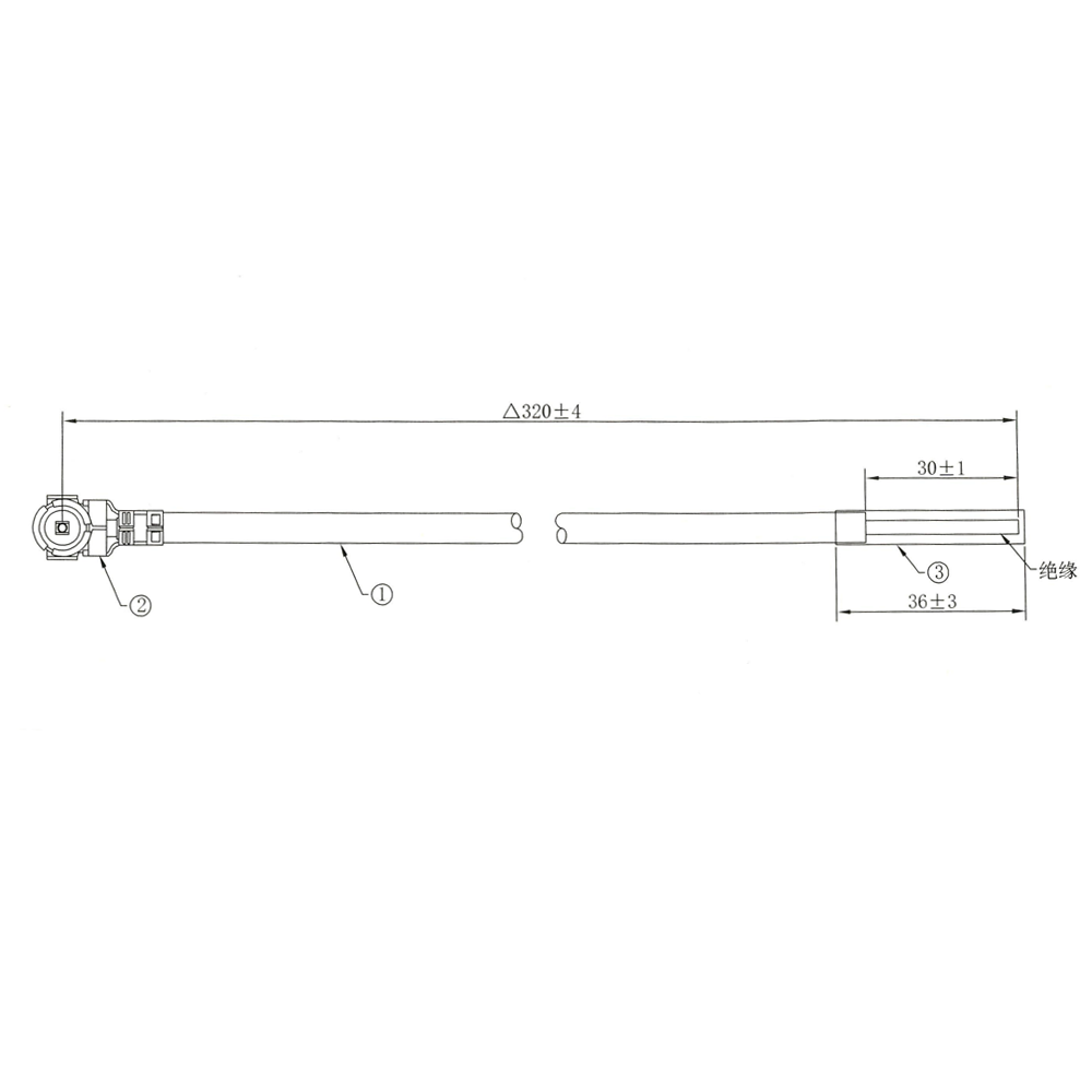
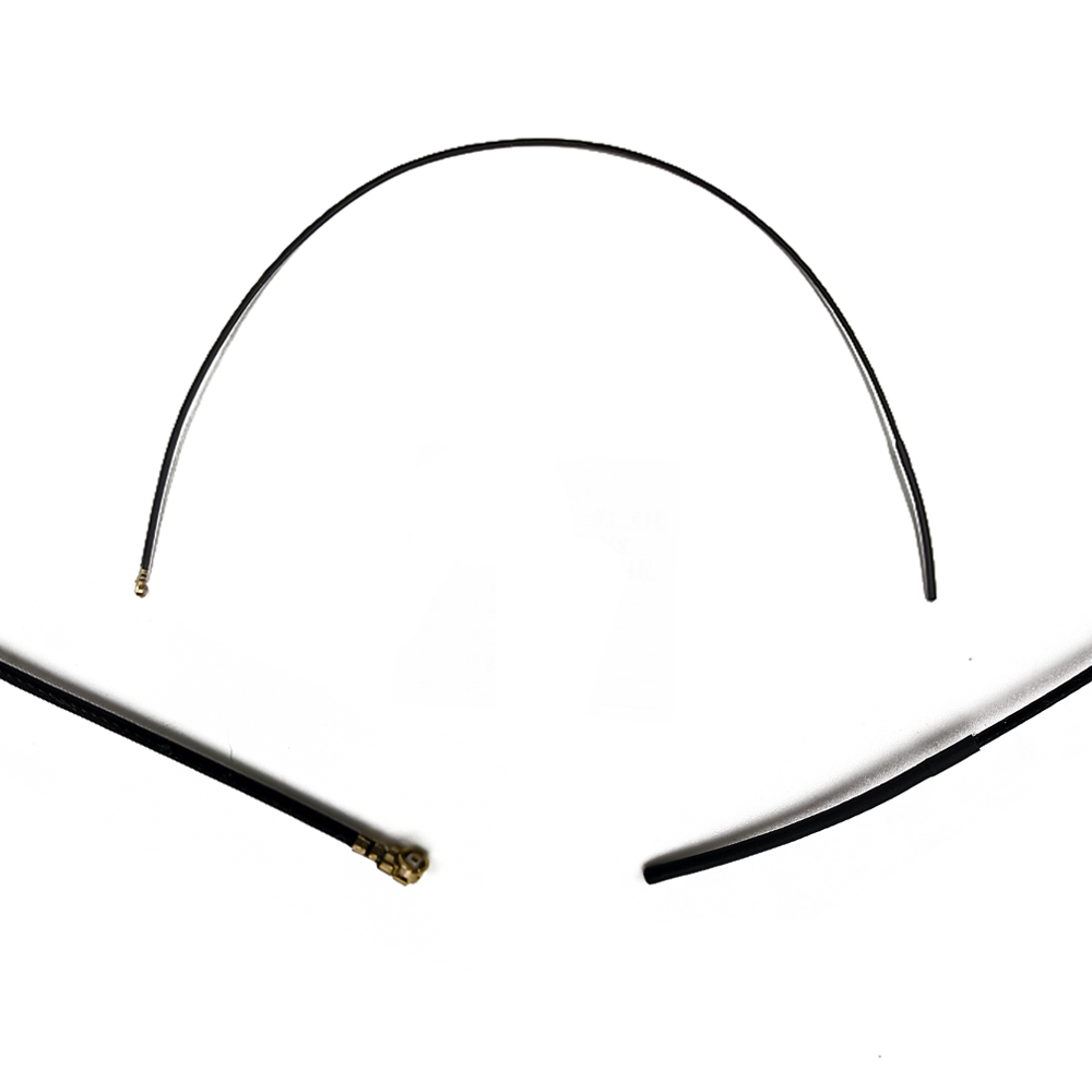
Due to their small size and often poor inherent efficiency, most compact GNSS antennas are active antennas. They incorporate a Low-Noise Amplifier (LNA) located immediately after the radiating element. This LNA provides 15-30 dB of gain to overcome downstream losses in the coaxial cable and to improve the signal-to-noise ratio before the signal reaches the receiver. This amplifier requires power, which is typically supplied through the RF cable via a bias tee circuit.
4. Construction for Real-World Environments:
The construction must account for the antenna's environment. Shielding cans are often placed over other components to prevent noise from contaminating the weak GNSS signal. The antenna's location is chosen to be a "clear zone," as far as possible from noise sources like processors, displays, and camera modules, and away from large metal blocks like batteries.
The operating principles of a low-profile compact GNSS antenna are the same as any antenna—the conversion of electromagnetic waves into electrical currents—but its operation is dominated by the challenges of its small size and its interaction with the host device.
1. The Fundamental Challenge of Small Size:
The efficiency and bandwidth of an antenna are fundamentally related to its electrical size. A classic rule of thumb is that an antenna becomes increasingly inefficient as its size is reduced below half a wavelength. At GNSS frequencies, a compact antenna is electrically very small. This results in three core issues:
High Q Factor: A small antenna has a high Quality (Q) factor, meaning it has a very narrow bandwidth. This makes it difficult to cover the entire bandwidth of a single GNSS band (e.g., ~20 MHz for L1) let alone multiple bands, without sophisticated design techniques.
Low Radiation Resistance: The radiation resistance of a small antenna is low, meaning a significant portion of the power is lost as heat (ohmic losses) in the metal and nearby dielectric materials rather than being radiated.
Increased Susceptibility to Detuning: The antenna's resonant frequency is easily shifted by nearby objects—the device's housing, the user's hand, or other components. This makes impedance matching a critical and often dynamic problem.
2. The Role of the Integrated LNA:
The integrated Low-Noise Amplifier is not merely an optional booster; it is a core part of the antenna system's functionality. Its primary roles are:
Overcoming Feedline Loss: The signal captured by the small, inefficient radiator is weak. If it traveled down a lossy cable to the receiver, it might be attenuated below the noise floor of the receiver itself. The LNA amplifies the signal at the source, so that even after cable loss, the signal presented to the receiver is strong.
Improving System Noise Figure: The noise figure of a cascaded system (antenna -> cable -> receiver) is dominated by the first component. By placing a very low-noise amplifier first, the overall system noise figure is minimized, which is crucial for detecting signals that are already below the thermal noise floor.
3. The Device as Part of the Antenna:
In a low-profile integration, the classic model of an antenna operating in free space is invalid. The device's PCB, metal chassis, and internal components become parasitic elements that drastically alter the antenna's performance. The currents excited on the antenna element couple to the larger ground plane, which then becomes the primary radiator. The antenna's final radiation pattern, polarization, and efficiency are thus properties of the entire device, not just the small ceramic patch or printed trace. This is why extensive simulation and testing in the final product form factor are absolutely essential.
4. Mitigating Degradation:
The antenna works in a hostile environment. Its operation involves constant battle against:
Multipath: While it lacks sophisticated choke rings, some multipath rejection is achieved by the antenna's pattern. If placed on a ground plane, it will naturally have reduced gain at very low elevations where reflected signals originate.
Interference: Out-of-band interference from cellular (4G/5G), Wi-Fi, and Bluetooth is mitigated by adding surface-acoustic-wave (SAW) filters either before or after the LNA within the antenna module.
User Interaction (Hand Effect): The biggest operational variable. The user's hand can block the signal, absorb RF energy, and detune the antenna's resonance. Advanced systems may use adaptive impedance matching networks to sense this detuning and dynamically retune the antenna to maintain a match and preserve performance.
The adoption of low-profile compact GNSS antennas is driven by compelling advantages for product design, but these are counterbalanced by significant technical challenges.
Advantages:
Form Factor and Aesthetics: The primary advantage. It enables the creation of sleek, thin, and aesthetically pleasing products with no external antennas, meeting consumer and industrial design demands.
Cost-Effectiveness: Particularly for PCB-embedded and ceramic patch designs, the antennas are extremely low-cost and amenable to automated, high-volume assembly (pick-and-place and reflow soldering), driving down the total bill of materials.
Robustness and Reliability: An embedded antenna is protected inside the device's housing. It is not susceptible to being broken off, snagged, or damaged through everyday use, increasing the product's overall durability and reliability.
Design Flexibility: Techniques like LDS offer immense freedom, allowing engineers to design the antenna into any available 3D space, wrapping around batteries or other components to maximize performance within tight constraints.
Integration Simplicity: For many applications, a pre-tuned, pre-certified ceramic antenna module simplifies the RF design process for engineers who may not be antenna specialists, reducing development time and risk.
Challenges:
Compromised Performance: This is the fundamental trade-off. Efficiency is often low (can be 20-50% compared to >70% for a good external antenna), directly impacting receiver sensitivity and time-to-first-fix (TTFF). Performance is often marginal in weak signal environments (urban canyons, under foliage).
High Design Dependency: Performance is not intrinsic to the antenna component but to the entire system integration. A perfect antenna design can be rendered useless by poor placement next to a battery or a noisy clock circuit. This requires expert RF design and extensive testing.
Susceptibility to Detuning: The antenna's performance is highly sensitive to its immediate environment. A change in plastic housing material thickness, a layer of paint, or the user's hand can shift the resonant frequency, causing a severe mismatch and signal loss.
Limited Bandwidth: Covering multiple GNSS bands (L1 + L5 + L2) with a single, very small element is extremely challenging and often results in poor performance on some bands.
Thermal Management: The integrated LNA consumes power and generates heat. In a tightly sealed device with no airflow, this can lead to thermal drift of the amplifier's characteristics and potentially affect the antenna element itself.
Low-profile compact GNSS antennas are the workhorses of the mass-market location ecosystem, enabling a vast array of applications.
Applications:
Consumer Electronics: Smartphones, smartwatches, fitness trackers, and tablets. This is the highest-volume application, where aesthetics and size are paramount.
Internet of Things (IoT): Asset trackers for logistics, wearable health monitors, smart sensors in agriculture, and micro-mobility devices (e-scooters, e-bikes). These devices are small, battery-powered, and require affordable, embedded connectivity.
Automotive Telematics: Insurance dongles (UBI), stolen vehicle recovery systems, and basic fleet tracking. The antenna is often hidden within the vehicle's dashboard or interior trim.
Drones and Robotics: Small drones and consumer robots require lightweight, low-drag navigation systems where protruding antennas are not feasible.
Portable Navigation Devices: Though largely supplanted by smartphones, dedicated handheld GPS units and wearable navigation devices for hiking rely on compact antennas.
Future Trends:
AI-Driven Antenna Design: Machine learning algorithms are being used to explore millions of geometric permutations to find non-intuitive antenna shapes that achieve maximum bandwidth and efficiency within a defined volume, surpassing human-designed solutions.
Advanced Materials: Research into new ceramic composites with lower loss tangents and more stable dielectric constants will improve efficiency. Metamaterials and magneto-dielectric materials could lead to breakthrough miniaturization.
Hybrid and Reconfigurable Antennas: Antennas that can dynamically alter their frequency response or radiation pattern using RF switches (PIN diodes, MEMS) or tunable materials (e.g., barium strontium titanate) to adapt to different bands or environments.
Tighter Integration with Chipsets: The boundary between the antenna and the receiver will blur. We will see co-designed systems where the antenna's limitations are compensated for by advanced digital signal processing algorithms within the GNSS System-on-a-Chip (SoC).
Dead Reckoning Fusion: As standalone GNSS performance in devices is often poor, there will be a greater emphasis on sensor fusion. The GNSS antenna will be part of a "navigation engine" that tightly integrates data from IMUs, wheel tick sensors, and camera feeds to provide continuous positioning when satellite signals are lost or degraded.
Conclusion
The low-profile compact GNSS antenna is a testament to the ingenuity of RF engineers in the face of formidable physical and commercial constraints. It represents a different design philosophy than precision antennas: one of optimal compromise rather than ultimate performance. Its success is measured not in millimeters of accuracy but in its ability to provide "good enough" location data to enable a world of applications that would otherwise be impossible.
It has been the key enabler for the miniaturization and commoditization of GNSS technology, putting a navigation receiver in nearly every pocket on the planet. The challenges of low efficiency, environmental susceptibility, and narrow bandwidth are very real, but they are being actively addressed through innovations in materials science, computational electromagnetics, and system-level integration. As the demand for smaller, more connected, and more intelligent devices continues to explode, the evolution of the low-profile compact antenna will remain at the forefront, ensuring that even the tiniest of devices can know its place in the world.

 86 0755 2819 9597
Lucy Yang | lucy.y@toxutech.com
Nicole Li | nicole@toxutech.com
Dotty Zhao | sales04@toxutech.com
Global Business Director / Sales Team / Global Operations


 En
En Cn
Cn Korean
 Home >


