

-
Products -PCBA Manufacturing RF Connectors RF Cable Assemblys Embedded Antennas External Antennas Positioning Chips and Modules
RF Connectors

RF Cable Assemblys
Embedded Antennas
External Antennas
Positioning Chips and Modules


 Language


Language


In the ever-expanding ecosystem of global navigation and connected devices, the antenna serves as the critical gateway between the digital world of a receiver and the physical signals transmitted from satellites orbiting 20,000 kilometers above the Earth. Among the myriad of antenna designs, the low-profile GPS ceramic patch antenna has emerged as a dominant form factor, enabling the proliferation of location-aware technology in consumer and industrial applications where space, aesthetics, and cost are paramount concerns.
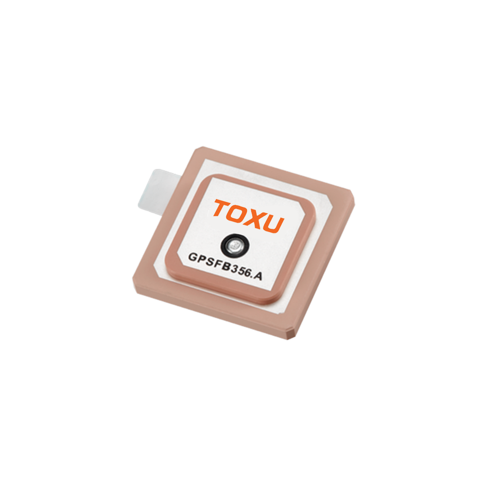
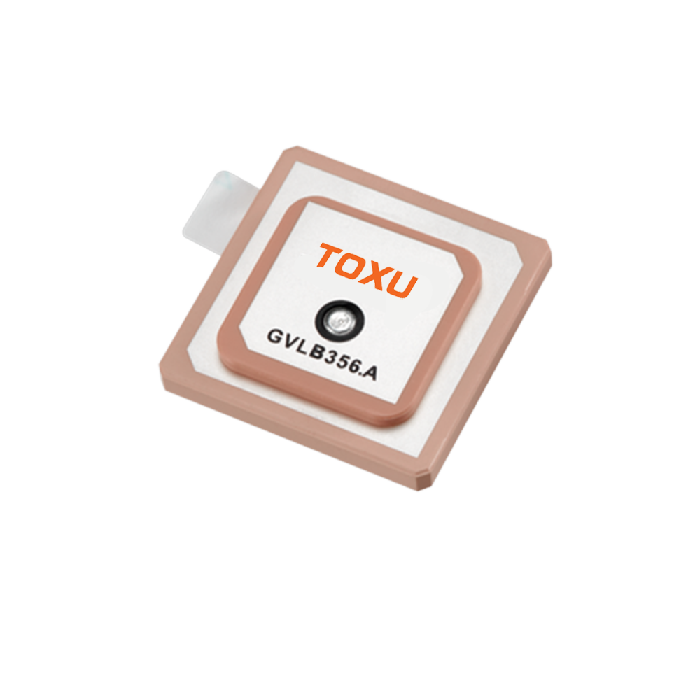
A low-profile GPS ceramic patch antenna is a type of microstrip antenna characterized by its flat, compact, and often square or circular design. Its "low-profile" nature means it has a minimal vertical height, typically ranging from just 3mm to 10mm, allowing it to be seamlessly integrated into the sleek housings of modern electronics without adding bulk. This physical attribute is its most immediately distinguishing feature, but the core of its functionality and widespread adoption lies in the use of a ceramic material as its substrate.
The genesis of this antenna type is rooted in the need to balance performance with the practical constraints of mass-produced devices. Traditional GPS antennas, like quadrifilar helices or dipoles, offered good performance but were often too large, bulky, or expensive for integration into handheld gadgets, wearable technology, or automotive telematics units. The ceramic patch antenna provided an elegant solution: a high-performance, cost-effective radiating element that could be manufactured at scale and mounted directly onto a printed circuit board (PCB) like any other surface-mount component.
The ceramic material is the key to its miniaturization. The substrate's dielectric constant (εᵣ) is a measure of how much it concentrates electric fields. Standard PCB materials like FR-4 have a relatively low εᵣ (~4.4). Ceramic materials used in these antennas, such as barium strontium titanate, have a very high εᵣ, often between 20 and 40. Since the physical size of a patch antenna is inversely proportional to the square root of the dielectric constant, a high εᵣ allows the antenna to be made dramatically smaller while still resonating at the target GPS frequency of 1575.42 MHz. This property is what enables a antenna to be just a few centimeters across and only millimeters thick.
These antennas are almost universally "active" designs, meaning they incorporate a Low-Noise Amplifier (LNA) within their assembly or immediately on the PCB beneath them. This is crucial because the signals from GPS satellites are incredibly weak by the time they reach the Earth's surface. The LNA boosts the signal right at the source, before it can be degraded by loss in the transmission line to the receiver, ensuring a strong and clear signal is delivered.
The applications for low-profile ceramic patch antennas are vast and touch nearly every aspect of modern life. They are the hidden enablers of location services in:
Consumer Electronics: Smartphones, tablets, smartwatches, and fitness trackers.
Automotive: In-car navigation systems, telematics control units (TCUs) for emergency calling and stolen vehicle tracking, and advanced driver-assistance systems (ADAS).
IoT and Asset Tracking: Logistics trackers, wildlife collars, and industrial sensors.
Drones and Robotics: Providing essential positioning for flight stability and autonomous navigation.
In summary, the low-profile GPS ceramic patch antenna is a masterpiece of engineering compromise. It represents the successful convergence of materials science, electromagnetic theory, and mass-production manufacturing. It sacrifices the ultimate performance of larger, specialized antennas to achieve a form factor that has made GPS technology ubiquitous, affordable, and invisible, powering the location-based services that have become an indispensable part of the connected world.
The design and construction of a low-profile GPS ceramic patch antenna is a meticulous process that involves careful trade-offs between electrical performance, physical dimensions, mechanical robustness, and cost. It is a multi-layered structure where each component and material choice is critical to the final antenna's functionality.
1. The Ceramic Substrate: The Foundation
The core of the antenna is the ceramic substrate. This is not a simple piece of pottery; it is a precisely engineered material with specific electromagnetic properties.
Material Composition: Typically, it is a blend of ceramic powders (e.g., barium neodymium titanate) mixed with binders and sintered at high temperatures to form a rigid, homogeneous slab. The exact配方 is a closely guarded secret among manufacturers, as it determines the key electrical properties.
Dielectric Constant (εᵣ): As mentioned, a high εᵣ (20-40) is selected to enable the small physical size. However, a higher εᵣ also typically results in a narrower bandwidth. Designers must strike a balance to ensure the antenna can cover the necessary ~20 MHz bandwidth around the GPS L1 center frequency and maintain performance across the required operating temperature range.
Loss Tangent (tan δ): This measures how much energy the substrate absorbs and converts to heat. A very low loss tangent is essential to ensure high radiation efficiency. The ceramic must be a very "good" insulator, allowing most of the energy to be radiated rather than dissipated within the material itself.
2. The Radiating Patch and Ground Plane
On the top and bottom surfaces of the ceramic substrate, conductive layers are applied.
Radiating Patch: On the top surface, a square, circular, or rectangular patch of conductive material (usually a silver or copper paste) is screen-printed or deposited. The dimensions of this patch (most critically its length, L) determine the resonant frequency of the antenna. The formula L ≈ c / (2f √εᵣ) guides this design, where c is the speed of light and f is the frequency.
Ground Plane: The entire bottom surface of the ceramic is coated with a continuous layer of conductor. This ground plane serves two vital functions: it acts as an electrical mirror to create the antenna's directional radiation pattern (broadside to the patch), and it provides isolation, shielding the antenna from the noise and interference generated by the electronics on the device's PCB below it.
3. The Feeding Mechanism
The method of delivering RF energy to the patch is a critical design choice. The two most common methods for ceramic patches are:
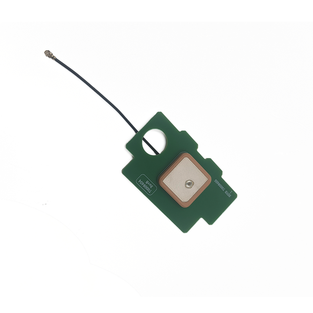
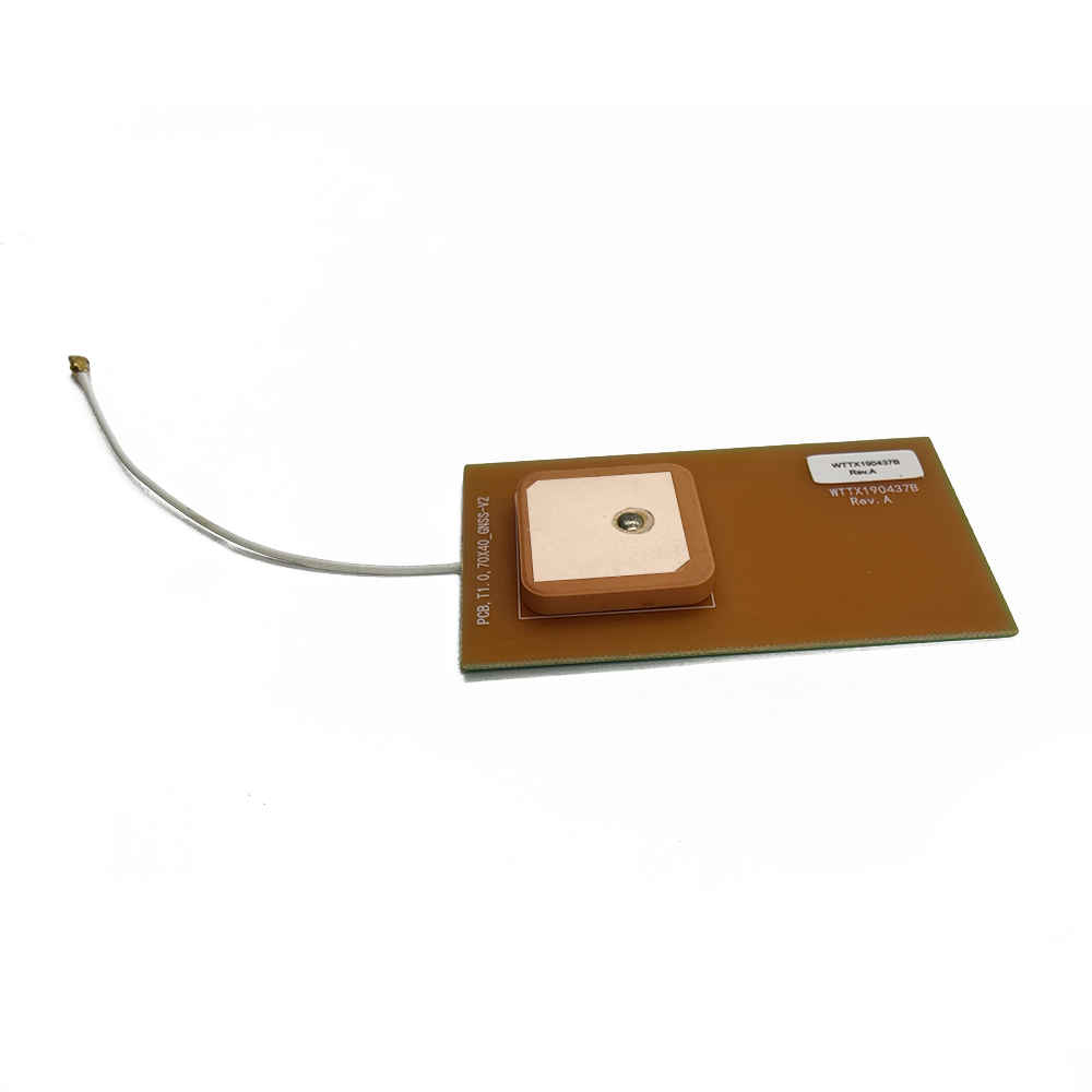
Probe Feed: A small hole is drilled through the ceramic substrate and the ground plane. A pin (the probe) is fed through this hole and soldered directly to the patch. The other end of the pin is soldered to the RF feed line on the host PCB. This is a simple and robust method but can introduce unwanted inductance.
Aperture-Coupled Feed (Advanced): A more sophisticated technique where the patch is not directly connected. Instead, the RF energy is coupled to it electromagnetically through a slot (aperture) in the ground plane. The feed line is a microstrip trace on a separate, standard FR-4 PCB underneath the ceramic element. This method offers better bandwidth and isolates the radiating element from the feed network, allowing for easier impedance matching.
4. The Low-Noise Amplifier (LNA)
The active component is typically a surface-mount amplifier chip placed on the host PCB directly beneath the antenna, though some integrated designs may place it adjacent to the patch. Its gain (often 15-28 dB) and, more importantly, its low noise figure (typically 0.8-1.5 dB), are selected to overcome downstream cable and connector losses. Power is supplied to the LNA via the same coaxial cable that carries the RF signal, using a DC bias circuit.
5. Construction and Assembly
The assembled unit is a marvel of miniaturization:
The ceramic element is manufactured and metallized.
The LNA and associated passive components (DC blocking capacitors, RF chokes) are assembled onto the PCB.
The ceramic element is placed over this assembly, often using a solder ring or conductive epoxy to make both the RF connection and a mechanical bond to the ground plane on the PCB.
A protective cover or lid is often placed over the ceramic. While not always waterproof, this lid protects the fragile ceramic from physical damage and contaminants.
The entire assembly is often encapsulated in a plastic housing or coated with a conformal material for environmental protection.
The entire process is designed for high-volume, automated production, allowing millions of units to be manufactured with consistent performance at a very low unit cost.
The operation of a low-profile ceramic patch antenna is an elegant application of fundamental electromagnetic principles, tailored for a specific frequency and physical form. Its function is to efficiently convert the electromagnetic energy from a passing GPS satellite into a guided electrical signal that can be processed by a receiver.
1. Resonance and Radiation
The antenna operates as a resonant cavity. The patch conductor and the ground plane form the two walls of a very shallow cavity, filled with the high-dielectric ceramic material. When RF energy at the GPS frequency is applied to the feed point, it excites a standing wave within this cavity.
The primary mode of operation is the TM₁₀ mode. In this mode, the electric field is oriented perpendicular to the patch and the ground plane, with its magnitude varying sinusoidally across the length of the patch. It is strongest (maximum) at the radiating edges of the patch and zero at the center. This fringing field at the edges is what radiates the electromagnetic energy into free space. The antenna's radiation pattern is directional, with its main lobe broadside (perpendicular) to the plane of the patch. This is ideal for GPS applications, as the user typically wants to point the antenna towards the sky where the satellites are.
2. The Role of the Ceramic Substrate
The high-dielectric ceramic substrate profoundly influences the antenna's operation:
Wavelength Reduction: The wavelength of an electromagnetic wave is reduced inside a dielectric material by a factor of 1/√εᵣ. For a ceramic with εᵣ = 36, the wavelength at 1.575 GHz is reduced from ~19 cm in free air to just ~3.2 cm inside the ceramic. This allows the resonant patch to be only about half of this reduced wavelength, or approximately 16mm on a side.
Field Confinement: The high dielectric constant concentrates the electromagnetic fields tightly within the substrate. This minimizes the interaction with nearby objects—a property known as de-tuning. This is why these antennas can perform reliably even when placed inside a plastic cell phone case next to a battery and other components. However, it also makes the antenna's performance more sensitive to the precise properties of the ceramic itself.
3. The Active Element: Signal Amplification
The working principle is incomplete without considering the LNA. The GPS signal arriving at the Earth's surface is extraordinarily weak, with a power spectral density below the thermal noise floor. The antenna's job is to capture this signal, but the tiny voltage induced on the patch is insufficient to overcome the losses in the transmission line to the receiver.
The LNA, positioned immediately after the radiating element, provides the necessary gain. It amplifies both the signal and the inherent environmental noise. Because it has a very low noise figure, it adds almost negligible noise of its own. This results in a significant boost in the Signal-to-Noise Ratio (SNR) at the output of the antenna module compared to its input. This "active antenna" design ensures that the signal delivered to the receiver is strong enough for the correlators inside the GPS chip to acquire and track the satellites, even when the antenna is connected via a lossy cable or when the satellite signals are partially obstructed.
4. Performance Characteristics in Practice
In a real device like a smartphone, the antenna's performance is a system-level property. The phone's PCB itself becomes part of the antenna system, acting as a ground plane extension. The phone's housing, the user's hand, and the surrounding environment all interact with the antenna's near field, slightly perturbing its impedance and radiation pattern. Modern antenna design accounts for this through extensive simulation and testing, often designing the antenna to perform adequately in a range of common usage scenarios rather than optimizing for a single ideal condition.
The low-profile ceramic patch antenna's dominance in consumer electronics is a direct result of its compelling advantages. However, achieving its small size and low cost requires accepting certain engineering trade-offs and challenges.
Advantages:
Extremely Low Profile and Small Form Factor: This is the primary advantage. Its minimal height and small footprint allow it to be integrated into devices where space is at an absolute premium, such as smartphones, wearables, and ultra-thin tracking modules, without compromising the industrial design.
Cost-Effective Mass Production: The design is highly amenable to automated, high-volume manufacturing processes like screen printing and pick-and-place assembly. This allows them to be produced for just a few dollars per unit, making GPS technology affordable for mass-market applications.
Mechanical Robustness: The solid ceramic substrate and surface-mount construction create a very rigid and durable assembly. It is highly resistant to vibration, shock, and physical deformation, which is crucial for devices that may be dropped or handled roughly.
Good Performance in Constrained Environments: The field confinement offered by the high-dielectric substrate makes the antenna less susceptible to de-tuning from nearby objects compared to a larger antenna with a lower εᵣ. This predictability simplifies integration into crowded electronic devices.
Simplified Integration: Being a surface-mount device (SMD), it can be automatically placed and soldered onto a PCB during the standard assembly process, just like a resistor or capacitor. This eliminates the need for manual assembly, separate cables, and connectors, further reducing cost and improving reliability.
Challenges and Limitations:
Inherently Narrow Bandwidth: This is the most significant technical limitation. The high dielectric constant that enables miniaturization also results in a high Q factor and a narrow impedance bandwidth. While sufficient for single-band GPS L1, this makes designing a single ceramic patch that covers multiple GNSS bands (e.g., L1, L2, L5, Galileo, BeiDou) extremely challenging. Multi-band designs often require more complex stacked or coupled patches, increasing cost.
Lower Efficiency and Gain: The electromagnetic fields concentrated in the ceramic substrate have more interaction with the lossy material, leading to lower radiation efficiency compared to larger antennas with air or low-loss foam substrates. Efficiency can range from 30% to 70% for good designs. This translates to lower gain, making them less sensitive to weak signals from satellites at low elevations or in obstructed environments.
Ground Plane Dependence: The antenna's performance is highly dependent on the size and quality of the ground plane it is mounted on. A small or irregularly shaped ground plane (common in compact devices) can severely distort the radiation pattern, reduce gain, and shift the resonant frequency. The antenna and PCB must be co-designed as a system.
Thermal Sensitivity: The dielectric constant of the ceramic material can vary with temperature. While manufacturers stabilize this as much as possible, extreme temperature swings can cause slight shifts in the antenna's resonant frequency, potentially degrading performance.
Susceptibility to Hand Effects: In handheld devices, the user's hand (composed largely of lossy water) placed near the antenna can absorb RF energy and detune the antenna, causing a significant drop in received signal strength. Device makers must carefully choose the antenna's location within the device to mitigate this.
Navigating the Trade-offs:
For the target applications—consumer devices where size, cost, and integration simplicity are more critical than ultimate performance—the advantages overwhelmingly outweigh the challenges. Engineers have developed sophisticated techniques to mitigate the limitations, such as using adaptive impedance matching networks to counteract de-tuning and advanced simulation software to optimize placement on the PCB. The low-profile ceramic patch antenna remains the optimal solution for bringing "good enough" GPS performance to the mass market.
The low-profile ceramic patch antenna is the workhorse of consumer and industrial GNSS, enabling a vast array of applications that rely on ubiquitous, affordable positioning. Its future is tied to the evolving demands of these applications and the relentless drive for further miniaturization and integration.
Current Applications:
Smartphones and Tablets: This is the highest-volume application. Nearly every smartphone on the market uses one or more ceramic patch antennas for GPS, and increasingly for other satellite systems like Galileo and BeiDou, to enable navigation, location-based services, geotagging, and emergency location (e.g., E911).
Wearable Technology: Fitness trackers, smartwatches, and personal safety devices rely on these tiny antennas to provide location tracking for exercise metrics, navigation, and emergency SOS features without adding bulk to the device.
Automotive Telematics: They are embedded in telematics control units (TCUs) for emergency call (eCall) systems, stolen vehicle tracking, usage-based insurance, and fleet management. Their ruggedness is ideal for the harsh automotive environment.
Asset Tracking and IoT: Small, low-power GPS trackers for logistics, supply chain management, and monitoring high-value assets almost exclusively use ceramic patch antennas due to their small size and suitability for battery-operated devices.
Drones and Robotics: Small drones (UAVs) use these antennas for basic positioning and return-to-home functions. They provide a good balance of performance and size for consumer and prosumer platforms.
Future Trends:
Multi-Band/Multi-Constellation Integration: The future of GNSS is multi-frequency (L1, L5) and multi-constellation (GPS, Galileo, GLONASS, BeiDou). The major challenge for ceramic patches is achieving this in a small form factor. Future designs will leverage:
Stacked Patches: Using multiple ceramic layers with patches tuned to different frequencies.
Advanced Feeding Techniques: Aperture-coupled and proximity-coupled feeds to better control coupling between bands.
Reconfigurable Antennas: Using tunable components (varactors, RF switches) to allow a single patch to cover multiple bands, though this adds cost and complexity.
Antenna-in-Package (AiP) and Integration with RF Front-End: The next step in miniaturization is to move beyond a separate SMD component and integrate the antenna directly into the IC package of the GNSS receiver chip itself. This "Antenna-in-Package" technology would represent the ultimate in size reduction and simplified design, though it presents immense technical challenges related to isolation and thermal management.
Enhanced Robustness to Interference: As the RF environment gets noisier with 5G, WiFi, and other services, future antennas may incorporate built-in filtering to reject out-of-band interference more effectively, preserving the sensitivity of the GNSS receiver.
Tighter Coupling with Other Technologies: The antenna will not be a standalone component but part of a fused sensor system. We will see more modules that combine the GNSS ceramic patch antenna with other wireless technologies like 4G/5G cellular, WiFi, Bluetooth, and even inertial sensors (IMUs) on a single board, providing a complete positioning and connectivity solution for OEMs.
Materials Innovation: Research into new ceramic and composite materials could yield substrates with even higher dielectric constants for further size reduction, or with tunable properties that can adapt to their environment.
The trend is clear: the antenna will continue to become smaller, more integrated, and more multifunctional, while the industry strives to overcome the fundamental physics challenges to improve its bandwidth and efficiency. It will remain the key to embedding location intelligence into an ever-expanding universe of connected devices.
Conclusion
The low-profile GPS ceramic patch antenna stands as a testament to the power of engineering compromise and innovation. It may not boast the raw performance of a large geodetic antenna with a choke ring, but it achieves something perhaps more significant: it made high-quality GPS technology accessible, affordable, and invisible. It is the component that democratized satellite positioning, moving it from a specialized tool for pilots and surveyors into a standard feature in the pockets of billions.
Its success is rooted in a perfect alignment with the needs of the consumer electronics revolution. Its small size, low cost, mechanical robustness, and ease of integration made it the only practical choice for manufacturers looking to add location capabilities to their products. It solved the critical problem of how to fit a functioning GPS antenna into a device that is relentlessly shrinking in size.
The antenna's working principle, leveraging the field-concentrating properties of high-dielectric ceramics, is an elegant solution to the problem of miniaturization. While this approach introduces trade-offs in bandwidth and efficiency, these have been deemed acceptable for the vast majority of applications. The industry has developed sophisticated design and integration techniques to mitigate these limitations and extract the best possible performance from these compact radiators.
Looking forward, the low-profile ceramic patch antenna is not a finished technology. It is evolving to meet the new demands of multi-band GNSS, tighter integration, and noisier RF environments. It will continue to be the fundamental bridge between the physical world of satellite signals and the digital world of location-based services. As we move into an era of autonomous systems, pervasive IoT, and immersive augmented reality, the humble ceramic patch will remain there, hidden from view but essential to function, quietly and reliably answering one of humanity's oldest questions: "Where am I?" Its low profile belies its enormous impact on modern technology and daily life.

 86 0755 2819 9597
Lucy Yang | lucy.y@toxutech.com
Nicole Li | nicole@toxutech.com
Dotty Zhao | sales04@toxutech.com
Global Business Director / Sales Team / Global Operations


 En
En Cn
Cn Korean
 Home >


