

-
Products -PCBA Manufacturing RF Connectors RF Cable Assemblys Embedded Antennas External Antennas Positioning Chips and Modules
RF Connectors

RF Cable Assemblys
Embedded Antennas
External Antennas
Positioning Chips and Modules


 Language


Language


In the vast, featureless expanse of the open ocean, where celestial navigation once reigned supreme, the silent, continuous chatter of global navigation satellite systems (GNSS) has become the lifeblood of modern maritime operations. At the heart of this electronic revolution is a critical yet often overlooked component: the GNSS antenna. Among these, the low-profile marine antenna has emerged as a dominant design, seamlessly integrating advanced performance with the practical demands of vessel architecture and safety. This overview delves into the fundamental role, evolution, and key characteristics of these pivotal devices, establishing why they are far more than just simple "GPS receivers."
The term "GNSS" encompasses all global satellite constellations, including the American GPS, the Russian GLONASS, the European Galileo, and the Chinese BeiDou, along with various regional augmentation systems (SBAS) like WAAS and EGNOS. A marine GNSS antenna is specifically designed to receive the incredibly weak signals broadcast from these satellites, orbiting over 20,000 kilometers above the Earth. Its primary function is the first and most crucial step in the positioning chain: to efficiently collect these faint radio frequency (RF) signals, amplify them with minimal added noise, and pass them to a receiver for processing into accurate position, velocity, and time (PVT) data.
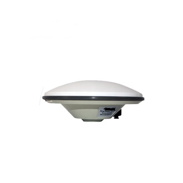
The evolution from traditional "shark fin" or pole-mounted antennas to today's low-profile models is a story of responding to maritime challenges. Early marine antennas were often bulky, top-heavy, and presented significant obstacles on deck. They were susceptible to damage from docking maneuvers, overhead obstacles like bridges, and were a safety hazard for crew moving on deck. The demand for a more streamlined, robust, and installation-friendly design catalyzed the development of the low-profile form factor. This design philosophy prioritizes a minimal vertical height—often just a few centimeters—while expanding the base's footprint. This creates a low center of gravity, significantly enhancing stability and reducing the risk of snagging or impact damage.
A key characteristic that defines a high-quality low-profile marine antenna is its radome—the protective outer shell. This is not merely a cosmetic cover; it is a critical engineered component. Marine radomes are constructed from materials like polycarbonate, ABS plastic, or fiberglass, chosen for their exceptional durability and, crucially, their radio frequency transparency. They must be entirely inert to the specific L-band frequencies used by GNSS signals (e.g., GPS L1: 1575.42 MHz, L2: 1227.60 MHz; GLONASS L1: 1602 MHz). Any attenuation or distortion of these signals by the radome material would severely degrade performance. Furthermore, these radomes are rigorously sealed to achieve an IPX6, IPX7, or even IPX8 rating, guaranteeing protection against powerful jets of water, temporary immersion, and constant exposure to salt spray, UV radiation, and extreme temperatures.
Internally, the antenna element itself is a marvel of precision engineering. Most modern low-profile antennas use a variant of a patch antenna element, which is inherently low-profile. These are typically arranged in arrays and mounted on a ground plane. The ground plane is fundamental; it acts as an electrical mirror, creating a directional radiation pattern that is focused upward towards the sky (hemispherical or zenith-facing) and rejects signals coming from below the horizon. This is vital for rejecting multipath interference—a phenomenon where signals bounce off the ship's superstructure or the water's surface, creating positioning errors.
Finally, another cornerstone of the modern low-profile antenna is the integrated Low-Noise Amplifier (LNA). The signal strength from GNSS satellites upon reaching the Earth's surface is astonishingly weak, often compared to trying to see a 25-watt light bulb from 12,000 miles away. The LNA's job is to boost this signal significantly (e.g., by 25 dB to 40 dB) before it travels down the coaxial cable to the receiver. Crucially, it must do this while adding the absolute minimum amount of electronic noise itself, quantified by a low Noise Figure (NF). A high-gain, low-noise LNA is essential for overcoming cable loss and ensuring a strong, clean signal reaches the receiver, enabling it to acquire and track satellites quickly and reliably, even in adverse conditions.
In summary, the low-profile GNSS marine antenna is a sophisticated convergence of materials science, electromagnetic theory, and electronic engineering. It represents a mature response to the harsh marine environment, offering a blend of ruggedness, reliability, and high performance that is essential for everything from basic chartplotting to advanced dynamic positioning and autonomous navigation. Its unassuming design belies its critical role as the foundational sensor upon which all modern marine electronic systems rely.
The design and construction of a low-profile GNSS marine antenna is a meticulous exercise in balancing conflicting demands: achieving peak electromagnetic performance while ensuring absolute resilience against one of the most corrosive and physically demanding environments on Earth. Every material, every curve, and every internal component is chosen and placed with intentionality. This section deconstructs the antenna layer by layer, exploring the engineering principles that transform it from a simple receiver into a hardened maritime sensor.
The Radome: The First Line of Defense
The radome is the antenna's shield. Its primary design goals are:
RF Transparency: It must be virtually invisible to the target L-band signals. Engineers use specific plastic polymers (e.g., polycarbonate blends, ABS) that have minimal dielectric loss at these frequencies. The thickness of the radome is also critical, as it can be tuned to act as an impedance matching layer or to avoid creating standing waves that could cancel out signals.
Environmental Sealing: The seal between the radome and the base is a critical failure point. High-end antennas use dual or triple sealing methods, often involving silicone gaskets and o-rings, combined with ultrasonic welding or specialized adhesives to create a hermetic seal. The ingress protection (IP) rating, such as IPX7 (immersion up to 1m for 30 minutes) or IPX8 (continuous immersion), is a non-negotiable specification.
Physical Durability: The radome must withstand direct impact, UV degradation from constant sun exposure, and extreme thermal cycling. Materials are often treated with UV inhibitors to prevent yellowing and embrittlement. The shape itself is designed to be strong, often with reinforced ribs on the inside, and sloped to shed water and prevent the accumulation of salt or debris.
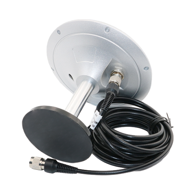
The Ground Plane: The Electrical Foundation
The ground plane is a conductive surface, typically made of stamped or milled aluminum, upon which the antenna element is mounted. Its functions are multifaceted:
Directionality: It creates the antenna's radiation pattern. A well-designed ground plane ensures the pattern is maximized towards the zenith (directly overhead) and has a wide beamwidth to receive satellites down to very low elevations (typically 5-10 degrees above the horizon), which is crucial for maintaining a good geometric dilution of precision (GDOP). Conversely, it sharply attenuates signals arriving from below the horizon, which are almost always destructive multipath reflections.
Impedance Matching: The size and shape of the ground plane are integral to presenting the correct electrical impedance (typically 50 ohms) to the antenna element, ensuring maximum power transfer from the element to the feed cable.
Shielding: It acts as an electrical barrier, protecting the sensitive antenna element from noise generated by the vessel's own electronics below deck.
The Antenna Element: The Heart of the System
The radiating element is where the magic of signal reception happens. The low-profile form factor almost universally dictates the use of a patch antenna or an array of patches.
Patch Antenna Basics: A single patch is a resonant structure, essentially a piece of microstrip transmission line. It's a flat, rectangular conductor separated from the ground plane by a dielectric substrate. Its resonant frequency is determined by its length.
Multiband Operation: Modern antennas must receive multiple frequencies from multiple constellations (e.g., GPS L1/L2/L5, GLONASS L1/L2, Galileo E1/E5a/E5b). This is achieved through sophisticated designs:
Stacked Patches: Using multiple patches of different sizes stacked on top of each other, each resonant at a different frequency.
Slotted or Notched Patches: Introducing precise cuts or slots into a single patch to perturb current paths and create multiple resonant modes.
Array Design: To enhance performance, particularly for demanding applications like heading or attitude determination, multiple antenna elements are arranged in an array within a single radome. By comparing the phase of the signal received by each element, the receiver can calculate precise orientation.
The Low-Noise Amplifier (LNA): The Signal Booster
Housed within the radome, directly behind the antenna element, is the LNA. Its design is paramount to system sensitivity.
Gain: Typically between 25 dB and 40 dB. This must be high enough to overcome downstream cable loss but not so high that it saturates the receiver's front-end with noise or strong out-of-band signals.
Noise Figure (NF): This is the most critical specification, often below 1.5 dB for premium antennas. A lower NF means the LNA adds less inherent noise, preserving the fragile signal-to-noise ratio (SNR) of the satellite signal.
Filtering: High-quality LNAs incorporate bandpass filters immediately at their input. These filters are designed to pass only the GNSS frequency bands (e.g., 1550-1610 MHz) and aggressively reject powerful out-of-band interference from sources like cellular networks (700-800 MHz, 1800-1900 MHz), VHF radios, and radar systems (often 3 GHz or 9 GHz). This filtering prevents the LNA from being overloaded or going into compression.
Surge and ESD Protection: Given the antenna's exposed location, the LNA circuitry must be protected from voltage spikes induced by lightning strikes (even distant ones) or electrostatic discharge (ESD). This is achieved with transient voltage suppression (TVS) diodes and other protective circuits.
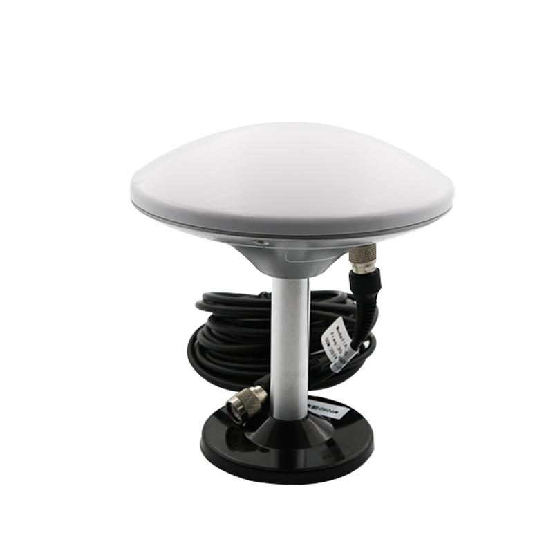
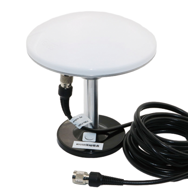
The Base and Mounting System: Secure Integration
The base is typically metal (e.g., die-cast zinc or aluminum) to provide weight, stability, and act as part of the ground plane. It features a standard mounting pattern, often compliant with the "AMPS" (Antenna Mounting Pattern Standard) hole pattern, allowing it to be fitted to a variety of mounts. The mounting hardware itself—stainless steel bolts, nuts, and washers—is specified to resist corrosion. The cable entry point is another critical seal, usually employing a compression gland with a rubber grommet to ensure a watertight connection for the coaxial cable.
In conclusion, the construction of a low-profile GNSS antenna is a holistic process where mechanical, environmental, and electrical design are inextricably linked. The choice of every material and the geometry of every component is a calculated decision aimed at achieving one goal: providing a supremely clean and stable signal from a device that can survive for years in the relentless marine environment.
The operation of a low-profile GNSS marine antenna is the critical first step in a complex chain of signal processing that culminates in the precise latitude, longitude, and altitude displayed on a chartplotter. Its function transcends simple reception; it is about selective, amplified, and clean signal acquisition. Understanding its working principles requires delving into the nature of the signals it receives, the phenomenon of multipath interference, and the electronics that condition the signal for the receiver.
The Nature of the GNSS Signal
GNSS satellites transmit spread-spectrum microwave signals in the L-band. These signals are incredibly weak by the time they traverse over 20,000 km of space and atmosphere. They arrive at the Earth's surface with a power level typically below -130 dBm (decibels relative to one milliwatt), which is billions of times weaker than the signal from a cell phone. Furthermore, they are buried in background thermal noise. The antenna's first job is to act as an "aperture," collecting this radiant energy. The effectiveness of this collection is quantified by its gain, measured in decibels isotropic (dBi). A marine antenna is designed to have positive gain towards the sky (e.g., +3 to +5 dBi) to improve signal collection.
The Radiation Pattern: Shaping Reception
The antenna's radiation pattern is a 3D representation of its gain in every direction. A perfect marine GNSS antenna would have a hemispherical pattern—like a bowl placed over the antenna—with maximum gain from the horizon up to the zenith, and zero gain below the horizon.
High-Elevation Performance: Strong gain at high elevations (directly overhead) is important for overall signal strength.
Low-Elevation Performance: The ability to receive signals from satellites low on the horizon is crucial for maintaining a good satellite geometry, which reduces Dilution of Precision (DOP) and improves positional accuracy. However, low-elevation signals are more susceptible to atmospheric delays and noise. Antenna designers carefully balance low-elevation gain to acquire these valuable satellites while filtering out the accompanying noise.
Backlobe Suppression: This is perhaps the most important aspect. The ground plane's primary electrical function is to eliminate the "backlobe"—-the portion of the pattern that would receive signals from below the antenna. Signals from below are, by definition, reflections (multipath) from the water's surface or the metal deck and superstructure of the vessel. By suppressing this part of the pattern, the antenna inherently rejects a major source of positioning error.
Multipath Mitigation: The Silent Battle
Multipath occurs when a satellite's signal takes multiple paths to the antenna—one direct and one or more reflected. The reflected signal travels a longer path and arrives at the antenna slightly delayed. When combined with the direct signal inside the receiver, this delay creates phase and code tracking errors, corrupting the pseudo-range measurement and degrading positional accuracy. The low-profile antenna fights multipath through:
Radiation Pattern Control: As mentioned, suppressing signals from below the horizon.
Advanced Element Design: Some high-precision antennas use specialized elements like choke rings or electrically coupled elements that create a "null" in their reception pattern at the angle where reflections are most likely to arrive, further canceling out multipath signals.
Signal Conditioning: The Role of the LNA and Filtering
The raw signal captured by the antenna element is useless to the receiver without conditioning.
Amplification (LNA): The integrated LNA provides the first and most critical stage of amplification. Because the signal is so weak, the noise performance of this first amplifier dictates the overall noise figure of the entire system (receiver + antenna + cable). This is why a low-noise figure (e.g., <1.5 dB) is paramount. The gain of the LNA (e.g., 30 dB) boosts the signal well above the noise floor introduced by the subsequent coaxial cable and the receiver's own front-end.
Filtering (Bandpass Filter): The marine RF environment is polluted with strong signals from other transmitters: VHF radios, AIS, radar, satellite communications, and cellular networks. A bandpass filter is placed either before or immediately after the LNA. Its sharp frequency response allows GNSS frequencies to pass unimpeded while attenuating all other frequencies. This prevents these powerful interfering signals from overloading the LNA or the downstream receiver, which would cause a total loss of GNSS tracking.
The Journey Down the Cable
The now-amplified and filtered signal is sent to the receiver via a coaxial cable. This cable itself introduces loss (attenuation), which is frequency-dependent and increases with cable length. The gain of the LNA is specifically chosen to be high enough to overcome this cable loss, ensuring the signal presented to the receiver is still strong and clear. The receiver then performs the complex tasks of de-spreading the signal, demodulating the navigation data message, calculating pseudo-ranges, and finally, using trilateration, determining the precise position, velocity, and time (PVT).
In essence, the working principle of the antenna is one of selective amplification and purification. It acts as a highly sensitive, directional ear, tuned to the faint whispers of satellites, amplifying those whispers to a shout while simultaneously silencing the cacophony of the marine RF environment and the deceptive echoes of multipath. It transforms a problem of detecting a needle in a haystack into a manageable electronic signal, enabling the receiver to perform its calculations with the highest possible accuracy and integrity.
The widespread adoption of low-profile GNSS antennas across all vessel types, from recreational yachts to massive commercial ships, is a testament to their significant advantages. However, their design philosophy also introduces specific challenges and limitations that engineers and users must acknowledge. This section provides a balanced analysis of the pros and cons inherent to this technology.
Advantages:
Enhanced Durability and Resilience: The single greatest advantage is their ruggedness. The low vertical profile presents a minimal target for physical impact from docks, bridges, rigging, crew, and cargo operations. Their robust radome construction and high IP ratings ensure they can withstand constant exposure to salt spray, UV radiation, rain, ice, and even being submerged by green water over the deck. This leads to lower maintenance, fewer replacements, and greater overall reliability.
Improved Safety and Ergonomics: The streamlined design eliminates protruding obstacles on deck, creating a safer working environment for crew members who need to move around quickly, especially in heavy weather. They are less likely to snag lines, nets, or clothing.
Superior Aesthetics and Integration: For vessel designers and owners, the low-profile form factor is far more aesthetically pleasing. It allows for a cleaner, more modern deck layout. Their design facilitates easier integration into other vessel structures, such as being flush-mounted into the roof of a pilot house, integrated into a mast, or embedded within a deck fixture, maintaining the vessel's clean lines.
Reduced Weight and Windage: The compact size and use of plastics and composites make them significantly lighter than traditional pole-mounted antennas. This reduces top-weight, which can marginally improve vessel stability. Furthermore, the smaller cross-sectional area presents less wind resistance, which is a minor but non-trivial factor for fuel efficiency and handling in high winds.
Excellent Multipath Rejection: The large, solid ground plane that is fundamental to the low-profile design is highly effective at creating a sharp, hemispherical radiation pattern. This provides inherent rejection of multipath signals reflecting off the deck and sea surface, a key factor in improving positioning accuracy, especially when the vessel is rolling or pitching.
Standardized Mounting: The widespread adoption of the AMPS hole pattern on the base simplifies installation, replacement, and upgrading. Mariners can be confident that a new antenna will fit existing mounts, and vice versa.
Challenges and Limitations:
Potential for Signal Obstruction: This is the most significant trade-off. By being mounted low on a deck or cabin top, the antenna is more susceptible to signal blockage from the vessel's own superstructure, masts, rigging, and cargo. A tall mast or a crane directly aft of the antenna can create a significant shadow, blocking satellites in that portion of the sky and degrading geometry (increasing HDOP/VDOP). Careful placement during installation is absolutely critical and more challenging than with a tall pole mount that can see over most obstacles.
Performance Variability with Location: The antenna's performance is highly dependent on its specific installation location on the vessel. An ideal location with a full 360-degree view of the sky is not always available. Performance can vary dramatically between a centerline mounting on an aft cabin roof versus a mounting on the side of a wheelhouse.
Limited Space for Advanced Features: The compact internal volume can be a constraint for incorporating more advanced features. For example, integrating a high-performance multi-frequency, multi-constellation antenna element array alongside a high-gain LNA and robust filtering within a very shallow housing requires exquisite engineering and comes at a higher cost.
Heat Dissipation: The LNA and other electronics generate heat. In a sealed, low-profile radome exposed to direct sunlight, internal temperatures can become very high. Managing this thermal load to ensure electronic components remain within their operational specifications and do not experience premature failure or performance drift (e.g., gain change with temperature) is a key design challenge.
The "One Antenna" Compromise: While excellent for general navigation, a single low-profile antenna may not be optimal for all applications. For instance, precise heading systems require two identical antennas separated by a precise baseline (e.g., 1-2 meters). Finding two locations on a vessel that satisfy the requirements for both antennas (clear view, same height, etc.) can be difficult. Similarly, applications requiring absolute zenith performance (e.g., for attitude determination on a rolling vessel) might be better served by a different antenna type, though modern low-profile designs have largely closed this gap.
In conclusion, the advantages of low-profile antennas—durability, safety, and integration—overwhelmingly outweigh their challenges for the vast majority of marine applications. The key to success lies in understanding their limitations, particularly regarding placement. A high-quality antenna installed poorly will always perform worse than a mediocre antenna installed in an optimal location. Therefore, the mariner must view the antenna and its installation as a single, integrated system critical to overall navigational performance.
The low-profile GNSS antenna has evolved from a simple navigation aid into a foundational sensor enabling a vast array of maritime systems. Its applications span the entire spectrum of the marine industry, and ongoing technological trends promise to further expand its capabilities and criticality.
Current Applications:
Primary and Redundant Navigation: The most fundamental application is providing position data to the vessel's primary chartplotter or Integrated Navigation System (INS). For safety, commercial vessels often carry multiple independent GNSS receivers, each with its own antenna, providing vital redundancy in case of a single system failure.
Automatic Identification System (AIS): A Class A or Class B AIS transponder is legally mandated on most commercial and larger recreational vessels. The AIS unit requires its own dedicated GNSS antenna to receive precise position and timing data for broadcasting the vessel's location, course, and speed to other vessels and shore stations. A low-profile antenna is ideal for this purpose.
Vessel Monitoring and Management: Fishing fleets, research vessels, and commercial shipping companies use GNSS data for fleet management, tracking vessel movements, optimizing routes for fuel efficiency, monitoring fishing grounds, and ensuring compliance with regulations.
Dynamic Positioning (DP) Systems: DP systems, used on drill ships, cable layers, and offshore support vessels, require extremely high levels of positional accuracy and integrity to maintain station. These systems utilize multiple GNSS antennas (often high-precision models with RTK or PPP capabilities) as their primary positional reference sensors. Their low-profile form is essential for installation on exposed deck areas without being damaged.
Heading and Attitude Determination: By using two or more synchronized GNSS antennas separated by a known baseline (a technique called GNSS compassing or vector processing), a vessel's precise heading, pitch, and roll can be calculated. This is a valuable alternative to traditional magnetic compasses, as it is immune to magnetic deviations and provides true North heading. Low-profile antennas are well-suited for these arrays on ship roofs.
Autonomous and Unmanned Vessels: The emerging field of Maritime Autonomous Surface Ships (MASS) is entirely dependent on robust and reliable sensor data. GNSS is the primary positioning sensor for autonomy algorithms. The durability and reliability of low-profile antennas make them the default choice for these applications, where maintenance may be infrequent or impossible.
Future Trends:
Multi-Band, Multi-Constellation Becomes Standard: The future is about leveraging all available signals: GPS L1/L2/L5, GLONASS L1/L2/L3, Galileo E1/E5a/E5b/E6, and BeiDou B1/B2/B3. Future antennas will be designed to receive all these frequencies with high efficiency. This provides massive redundancy, improves accuracy through better satellite geometry, and enables advanced error correction techniques.
Integrated Inertial Navigation Systems (INS): We will see more antennas with built-in Micro-Electro-Mechanical Systems (MEMS) inertial sensors (accelerometers and gyroscopes). This creates a deeply coupled INS-GNSS system within the antenna housing itself. When satellite signals are lost (e.g., in bridges, under heavy canopy, or due to extreme vessel motion), the inertial system provides dead reckoning, seamlessly bridging the gaps in GNSS coverage.
Advanced Interference Mitigation: The RF environment is becoming noisier. Future antennas will incorporate more sophisticated active filtering and adaptive nulling techniques to detect and reject both intentional (jamming) and unintentional interference, ensuring continuous operation even in congested ports or hostile scenarios.
Aperture-Level Integration: For high-precision applications, antennas will move beyond simple elements to fully integrated "apertures" where the antenna and receiver are co-designed as a single unit. This allows for advanced signal processing techniques at the element level, further suppressing multipath and interference before the signal is even digitized.
Smart Antennas and Networked Systems: Antennas will become intelligent nodes on a vessel's network. They could self-diagnose performance, report signal health, automatically calibrate for cable length, and seamlessly integrate data from other sensors, providing a fully-corrected and integrity-checked PVT solution over a standard Ethernet or NMEA 2000 connection.
Materials and Manufacturing Innovation: Additive manufacturing (3D printing) could allow for the creation of complex, lightweight radomes and ground plane structures that were previously impossible to manufacture, optimizing aerodynamic and hydrodynamic properties and RF performance simultaneously.
In summary, the low-profile GNSS antenna is not a static technology. It is rapidly evolving from a passive receiver into an intelligent, integrated sensor hub. Its applications are growing in both scope and criticality, forming the indispensable foundation for safer, more efficient, and ultimately autonomous maritime operations. The trend is clear: more functionality, more resilience, and more intelligence will be packed into the same rugged, low-profile form factor.
Conclusion
The journey through the design, principles, and applications of the low-profile GNSS marine antenna reveals a device of remarkable sophistication and critical importance. It is a powerful testament to the principle that true engineering excellence lies not in complexity for its own sake, but in the elegant resolution of conflicting demands. The low-profile antenna successfully marries the seemingly opposite needs of uncompromising performance and brutal environmental ruggedness into a single, compact, and reliable package.
Its significance cannot be overstated. It is the fundamental data source, the "prime sensor," for the entire ecosystem of modern marine electronics. Every precise position on a digital chart, every AIS target on a screen, every automated steering command, and every dynamic positioning hold command originates as a faint microwave signal captured by this unassuming device. Without its ability to perform this first critical step—acquiring a clean, amplified signal while rejecting noise and multipath—the most powerful and expensive GNSS receiver onboard would be rendered useless.
The evolution towards multi-frequency, multi-constellation reception, coupled with advanced integration with inertial and other sensors, is cementing its role not just as a navigational tool, but as a safety-critical system. For autonomous operations, its reliability transcends convenience and becomes an absolute prerequisite for viability. The lessons learned from its design—the importance of material science, precise electromagnetic engineering, and holistic system integration—are a blueprint for developing any technology intended for the harsh marine world.
For the mariner, the choice and installation of a GNSS antenna is one of the most consequential decisions for the vessel's electronic navigation capability. Selecting a high-quality, marine-grade low-profile antenna and installing it in a location with the clearest possible view of the sky is an investment in safety, efficiency, and operational capability. It is a piece of equipment that works tirelessly and silently, often forgotten until it fails, underscoring its role as a true unsung hero of the seas.
In conclusion, the low-profile GNSS marine antenna is far more than a simple accessory. It is a mature, highly evolved, and indispensable component that sits at the very beginning of the data chain that powers modern maritime navigation. As technology advances towards greater autonomy and connectivity, its function will only grow in importance, ensuring that vessels, from the smallest sailboat to the largest container ship, can know their place on the globe with confidence and precision, regardless of the conditions they face.

 86 0755 2819 9597
Lucy Yang | lucy.y@toxutech.com
Nicole Li | nicole@toxutech.com
Dotty Zhao | sales04@toxutech.com
Global Business Director / Sales Team / Global Operations


 En
En Cn
Cn Korean
 Home >


