

-
Products -PCBA Manufacturing RF Connectors RF Cable Assemblys Embedded Antennas External Antennas Positioning Chips and Modules
RF Connectors

RF Cable Assemblys
Embedded Antennas
External Antennas
Positioning Chips and Modules


 Language


Language


In an era defined by connectivity and precision location data, the Global Navigation Satellite System (GNSS) has become the invisible backbone of countless technologies, from the smartphone in your pocket to the autonomous vehicle on the road. At the heart of every GNSS receiver's ability to hear the faint whispers from satellites orbiting over 20,000 kilometers away lies a critical component: the antenna. Among the various antenna types, the low-profile GNSS ceramic antenna has emerged as the predominant solution for modern, miniaturized consumer and industrial electronics. This overview delves into the fundamental role, historical context, and key characteristics of these ubiquitous yet often overlooked devices.
A GNSS antenna's primary function is to efficiently capture the right-hand circularly polarized (RHCP) microwave signals transmitted by satellite constellations like GPS (USA), GLONASS (Russia), Galileo (EU), and BeiDou (China). These signals are extraordinarily weak by the time they traverse the atmosphere and reach the Earth's surface, with power levels often compared to viewing a 25-watt light bulb from 20,000 kilometers away. Therefore, the antenna must not only be sensitive but also highly selective, filtering out noise and interference while amplifying the desired signals.
The evolution towards ceramic patch antennas represents a response to the market's relentless drive for miniaturization, performance, and cost-effectiveness. Before their widespread adoption, early GNSS systems often relied on larger helical or quadrifilar helix antennas, which offered excellent performance but were bulky and unsuitable for integration into small devices. The development of the microstrip patch antenna, fabricated on a ceramic substrate, revolutionized the design language of portable electronics. The term "low-profile" is key; these antennas have a height (or thickness) typically measured in mere millimeters, allowing them to be seamlessly embedded into the chassis of products like smartwatches, trackers, drones, and automotive telematics units without protruding.
The choice of ceramic as the substrate material is not arbitrary. Ceramics, specifically materials like aluminum oxide (Al2O3) or more advanced formulations doped with titanium dioxide or other compounds, possess excellent dielectric properties for high-frequency applications. They have a high relative permittivity (dielectric constant, often denoted as εr). This high εr is crucial because it allows the electromagnetic waves to wavelength within the material to be significantly shorter than in air. This physical property enables the creation of a resonant patch element that is much smaller than a free-space wavelength antenna. For instance, the L1 GNSS frequency (1575.42 MHz) has a free-space wavelength of approximately 19 cm. A traditional antenna might be a quarter of this size (~4.75 cm). A ceramic antenna with a high εr can reduce this size by a factor of roughly the square root of εr (√εr). A ceramic with an εr of 20 allows for a patch size reduction of about 4.5 times, bringing the element size down to a compact centimeter-scale dimension.
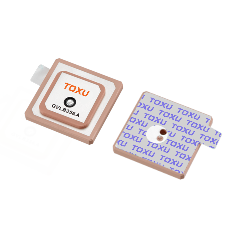
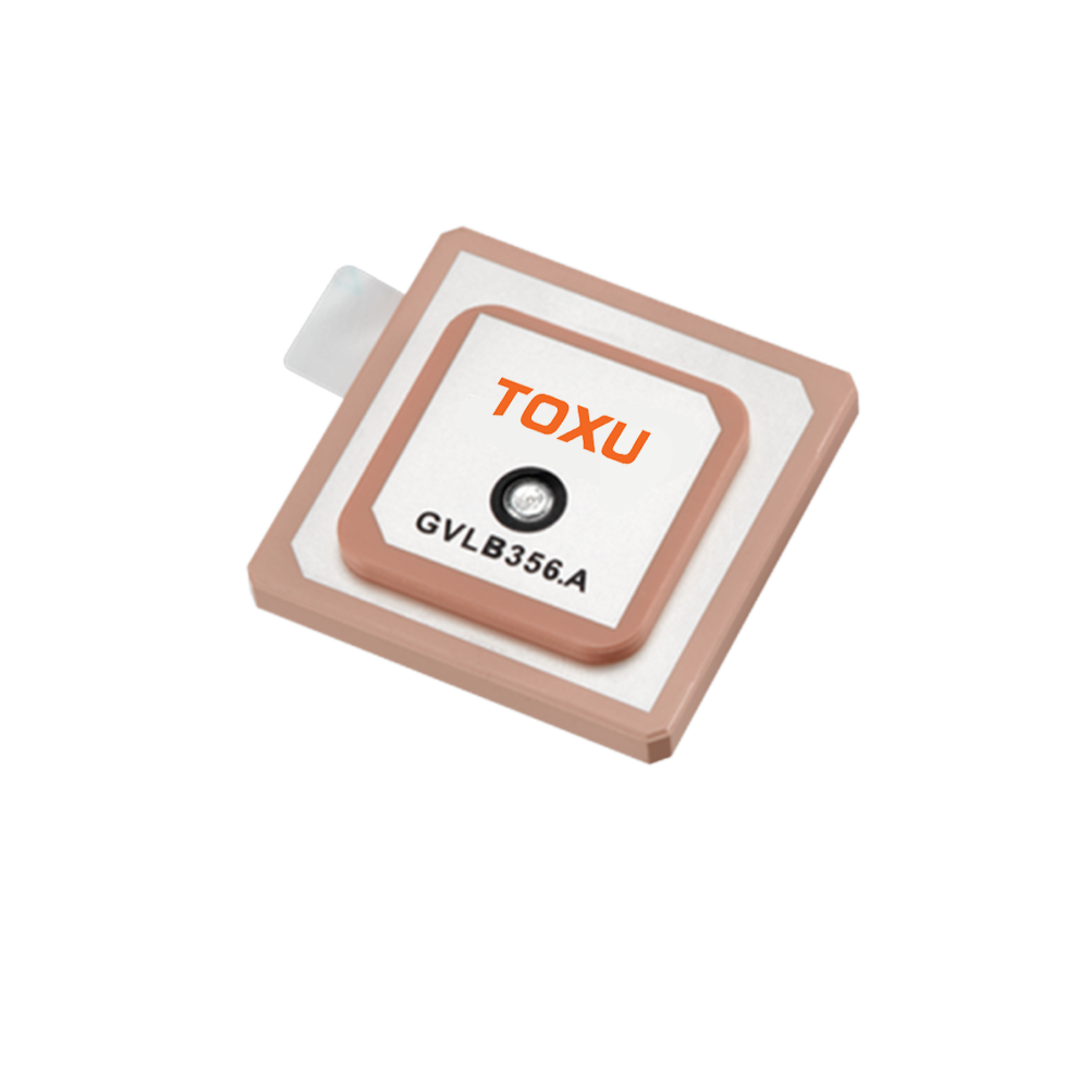
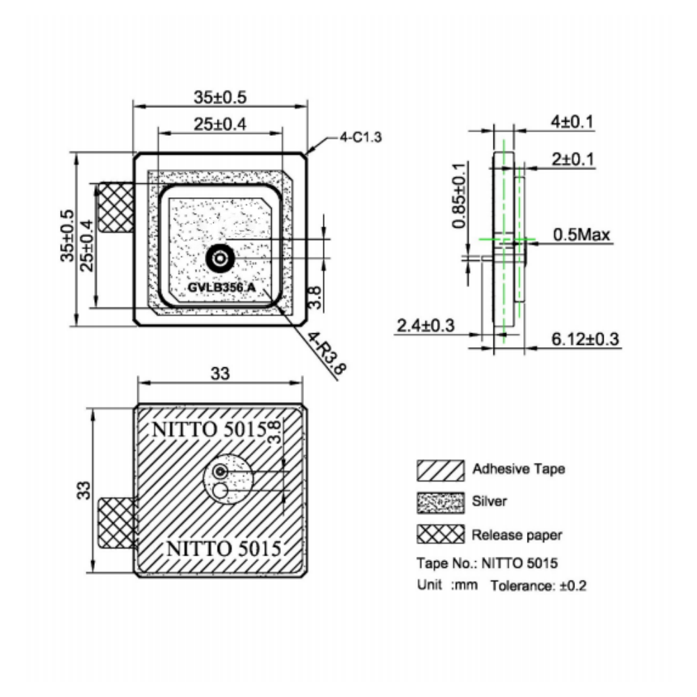
A typical low-profile GNSS ceramic antenna is a multi-layer structure. It consists of a radiating patch element, a ceramic dielectric substrate, a ground plane, and a feeding mechanism. The entire assembly is often housed in a surface-mount technology (SMT) compliant package, making it ideal for automated pick-and-place assembly processes on printed circuit boards (PCBs). This "chip antenna" form factor has been instrumental in mass production.
The performance of these antennas is quantified by several key parameters: Bandwidth must be wide enough to cover multiple GNSS bands (e.g., L1, L2, L5). Gain must be sufficient to acquire and track satellite signals, often characterized by a near-hemispherical radiation pattern to see satellites from horizon to zenith. Axial Ratio is critical to efficiently receive circularly polarized signals; a perfect circular antenna has an axial ratio of 0 dB, but practical designs aim for below 3-4 dB. Efficiency measures how much input power is actually radiated, with losses occurring in the ceramic, the conductors, and through impedance mismatches.
In summary, the low-profile GNSS ceramic antenna is a masterpiece of engineering compromise. It elegantly balances the conflicting demands of physical size, electrical performance, bandwidth, ruggedness, and manufacturing cost. Its development has been a key enabler for the proliferation of location-aware devices, transforming GNSS from a specialized military and survey tool into a ubiquitous utility embedded in the fabric of daily life. As we demand more from our devices—faster acquisition, higher accuracy, better reliability in challenging environments—the evolution of this humble component continues to be a area of intense research and innovation.
The design and construction of a low-profile GNSS ceramic antenna is a sophisticated process involving materials science, electromagnetic theory, and precision manufacturing. It is far more than a simple piece of metal on ceramic; it is a carefully engineered system where every layer and dimension plays a critical role in determining its final performance. This section deconstructs the anatomy of a typical ceramic patch antenna, exploring its materials, layers, feeding techniques, and the intricate design process.
Core Materials: The Ceramic Substrate
The foundation of the antenna is the ceramic substrate. Its properties are the primary determinants of the antenna's size, bandwidth, and efficiency.
Dielectric Constant (εr): As established, a high εr (typically ranging from 9 to 40+) is necessary for miniaturization. However, this advantage comes with a trade-off: higher εr generally leads to narrower bandwidth and lower radiation efficiency. This is because a greater concentration of the electromagnetic field within the lossy dielectric material increases ohmic losses. Designers must therefore carefully select a ceramic material with an εr that provides the best compromise for the target application size and performance.
Loss Tangent (tan δ): This measures the inherent signal loss within the ceramic material itself. A lower loss tangent is always desirable, as it directly translates to higher antenna efficiency. Premium ceramics boast very low loss tangents (e.g., 0.002 or lower) at GHz frequencies, ensuring more of the energy is radiated rather than converted into heat.
Temperature Stability: The dielectric constant should remain stable over the device's operational temperature range (e.g., -40°C to +85°C). Variations in εr with temperature would cause the antenna's resonant frequency to drift, potentially detuning it and degrading performance. Ceramic formulations are engineered for high temperature stability.
Common Materials: Common materials include Titanate-based ceramics (e.g., BaTiO₃, offering very high εr), Alumina (Al₂O₃, moderate εr ~9-10, excellent stability), and more advanced, proprietary blends that optimize all parameters.
Layered Structure: Building from the Ground Up
A standard ceramic antenna is a multilayer assembly:
Ground Plane: The bottom layer is a continuous metal plane (usually silver or copper) that serves as the electrical ground. It is essential for the antenna's operation, as the radiating patch and the ground plane together form a resonant cavity. The size of the ground plane on the host PCB is a critical external factor; too small a ground plane severely detunes the antenna and distorts its radiation pattern.
Ceramic Layer: This is the thick, monolithic block of engineered ceramic that sits on top of the ground plane.
Radiating Patch: A precisely shaped metal patch (again, silver or copper) is fabricated on the top surface of the ceramic. This patch is not a simple square; its geometry (often square or rectangular but sometimes with slots, notches, or other features) is carefully designed to resonate at the target GNSS frequencies and to excite the desired radiation modes.
Feed Structure: This is the mechanism to transfer energy from the receiver's RF input port to the radiating patch. The two most common methods are:
Probe Feeding: A conductive pin (probe) is connected from the ground plane, through a hole in the ceramic, to the patch. The location of this feed point relative to the center of the patch determines the input impedance (typically 50Ω).
Aperture Coupling (Slot Feeding): A more advanced technique where the patch is not directly connected to the feed line. Instead, a microstrip feed line on the host PCB runs beneath the ground plane. A slot is etched in the ground plane, and energy couples from the feed line, through the slot, into the patch above. This method allows for better optimization of bandwidth and impedance matching separately from the patch resonance.
Protective Layer: A thin ceramic or other non-conductive layer may be placed over the patch to protect it from environmental factors and physical damage during handling.
The Design Process: Simulation and Iteration
Modern antenna design is heavily reliant on Electromagnetic (EM) simulation software. Tools like ANSYS HFSS, CST Studio Suite, and Keysight ADS are industry standards. The process is highly iterative:
Initial Parameters: The designer defines constraints: target frequency, bandwidth, physical size, and available ground plane size.
Material Selection: A ceramic with appropriate εr and tan δ is chosen.
Modeling: A 3D model of the antenna is built in the simulator, including the ceramic block, patch, feed, and a model of the host PCB with its ground plane.
Simulation: The software solves Maxwell's equations for the model, predicting performance parameters like S11 (return loss, indicating impedance matching), radiation pattern, gain, axial ratio, and efficiency.
Optimization: The designer adjusts geometric parameters—patch size and shape, feed point location, slot dimensions (if used)—and re-runs simulations until the performance meets the targets. This process can involve hundreds of iterations.
Prototyping and Validation: Once simulated performance is satisfactory, physical prototypes are manufactured and tested in an anechoic chamber. Measured data is compared against simulation results to validate the model and make final tweaks.
Advanced Construction Techniques
To enhance performance, especially for multi-band operation (e.g., simultaneous reception of L1, L2, and L5 bands), more complex structures are employed:
Stacked Patches: Two or more patch elements are stacked on top of each other, separated by dielectric layers. Each patch can be tuned to a different resonant frequency, creating a broader overall bandwidth.
Slotted Patches: Introducing slots or grooves into the patch surface can perturb the current flow, creating multiple resonant paths and thus broadening the bandwidth or enabling dual-band operation.
Laser Trimming: After manufacturing, the patch can be minutely adjusted using a laser to trim its dimensions, fine-tuning the resonant frequency to account for minor manufacturing variances.
In conclusion, the construction of a low-profile GNSS ceramic antenna is a precise and multi-disciplinary endeavor. It transforms the theoretical advantages of high-dielectric ceramics into a practical, high-performance component through meticulous design, advanced simulation, and precision manufacturing. Every aspect, from the molecular composition of the ceramic to the micron-level placement of a feed probe, is optimized to create a robust and efficient window to the satellite constellations above.
To understand how a low-profile ceramic antenna functions, one must delve into the fundamental principles of electromagnetism and antenna theory. Its operation is an elegant application of resonator physics, transforming electrical signals into electromagnetic waves and vice versa. This section explains the core working principles, including resonance, radiation mechanism, polarization, and the critical role of the ground plane.
The Resonant Cavity and Half-Wavelength Principle
At its core, a patch antenna is a resonant cavity. The structure formed by the metal patch on top, the ceramic dielectric in the middle, and the ground plane at the bottom acts as a cavity bounded by conductors on two sides and dielectrics on the others. The patch itself acts as a resonant element. The most fundamental mode of operation for a rectangular patch is the TM₁₀ (Transverse Magnetic) mode.
The length (L) of the patch is the primary dimension determining the resonant frequency. For a simple patch in air, the length is approximately half of the wavelength in the dielectric medium. The formula is given by:
L ≈ λ₀ / (2 * √εr)
where:
L = Length of the patch
λ₀ = Free-space wavelength (e.g., ~0.19m for L1 band)
εr = Relative permittivity (dielectric constant) of the substrate
This equation clearly shows the miniaturization effect. For a ceramic with εr = 20, the required patch length is reduced by a factor of √20 ≈ 4.47, bringing it down to a manageable ~21 mm for the L1 frequency. The width (W) of the patch affects the impedance bandwidth and radiation efficiency but has a lesser effect on the resonant frequency.
Radiation Mechanism: Fringing Fields
A common question is: how does such a flat structure radiate? The radiation occurs from the fringing fields at the edges of the patch. The electric field lines are concentrated between the patch and the ground plane. At the resonant frequency, these fields "fringe" out beyond the edges of the patch into space. The two radiating edges (the edges of length L) act like two radiating slots separated by a distance L. These slots are responsible for the radiation. The fields from these two slots add up in phase in the broadside direction (perpendicular to the plane of the patch) and cancel out in the direction along the patch, creating the antenna's characteristic radiation pattern.
Impedance Matching and Feeding
For maximum power transfer, the impedance of the antenna at its feed point must match the impedance of the transmission line feeding it, which is almost universally 50Ω in RF systems. The input impedance of the patch is not uniform across its surface. It is highest at the center (the voltage maximum, current minimum) and lowest at the edges (voltage minimum, current maximum). By placing the feed point at a specific location between the center and the edge, the designer can set the input impedance to exactly 50Ω. This is why the feed point location is a critical optimization parameter in the design process.
Right-Hand Circular Polarization (RHCP)
GNSS satellites transmit RHCP signals to mitigate signal degradation caused by Faraday rotation in the ionosphere and to be less sensitive to the orientation of the receiving antenna. A simple patch antenna is linearly polarized. To achieve circular polarization, the antenna must radiate two orthogonal components of the electric field that are equal in magnitude and 90 degrees out of phase.
This is achieved in patch antennas by introducing a geometric perturbation that creates two degenerate orthogonal modes with a 90° phase shift. Common techniques include:
Single-Feed with Truncated Corners: Truncating two opposite corners of a square patch is a simple and common method. The truncation unbalances the structure, exciting two modes with the required phase relationship.
Single-Feed with a Slot: Inserting a narrow slot near the center or at a specific location on the patch can also achieve the same effect.
Dual-Feed with 90° Hybrid Coupler: A more complex but higher-performance method uses two separate feed points placed orthogonally. A 90° hybrid coupler (or a simpler phase delay line) is used on the PCB to feed the two points with a precise 90° phase difference. This method allows for better control and a wider axial ratio bandwidth.
The quality of the circular polarization is measured by the Axial Ratio (AR). A perfect circularly polarized wave has an AR of 1 (0 dB). A practical GNSS antenna aims for an AR below 3 dB across its field of view, especially at low elevation angles, to ensure it can efficiently receive signals from satellites near the horizon.
The Role of the Ground Plane
The ground plane is not a passive participant; it is an integral part of the antenna system. It serves multiple functions:
Creates the Resonant Cavity: It forms the lower boundary of the cavity resonator.
Shielding: It provides shielding from noise and interference emanating from the electronic components on the other side of the PCB.
Directs Radiation: The size of the ground plane significantly shapes the radiation pattern. An ideally sized ground plane (typically larger than the patch by a wavelength or more) creates a clean, hemispherical pattern. A too-small ground plane causes pattern distortion, reducing gain at low elevation angles and making satellite acquisition difficult. This is why the antenna manufacturer's datasheet always specifies a minimum required ground plane size.
In essence, the low-profile ceramic antenna works by confining electromagnetic energy within a high-dielectric cavity, exciting a resonant mode, and then radiating that energy via fringing fields at its edges. Through careful design, it is engineered to be highly sensitive to very weak, circularly polarized signals arriving from almost any direction in the upper hemisphere, while rejecting unwanted noise and interference. It is a resonant system where every parameter is intricately linked, transforming a
The dominance of low-profile ceramic antennas in the GNSS market is a testament to their compelling advantages. However, like any technology, they are not a perfect solution and come with inherent challenges and trade-offs that designers must navigate. This section provides a balanced analysis of their strengths and weaknesses.
Advantages
Miniaturization and Low Profile: This is the most significant advantage. Their ability to achieve resonance at a fraction of the free-space wavelength allows them to be integrated into incredibly thin and small devices where traditional antennas are impossible. This has been the key enabler for the wearable and IoT markets.
Surface-Mount Technology (SMT) Compatibility: They are supplied in standard SMT packages (e.g., 25x25mm, 18x18mm, 15x15mm, and even smaller). This allows for fully automated assembly using pick-and-place machines and reflow ovens, drastically reducing manufacturing costs and improving consistency compared to manual assembly of external antennas.
Mechanical Robustness and Reliability: The monolithic ceramic structure is very rigid and resistant to vibration, shock, and corrosion. Once soldered to a PCB, they form a strong mechanical bond. They have no moving parts or fragile external elements, making them ideal for harsh environments, including automotive applications.
Consistent Performance and Repeatability: Being manufactured in high-volume, precision-controlled processes, they exhibit very consistent electrical characteristics from one unit to the next. This predictability is crucial for mass production, as it eliminates the need for tuning or calibration on each individual device.
Good Performance Profile: When designed and integrated correctly, they offer very good performance for their size. They provide a near-hemispherical radiation pattern, which is ideal for seeing satellites from the horizon to directly overhead. They also naturally provide good out-of-band rejection, acting as a filter against some cellular and WiFi interference.
Cost-Effectiveness at Scale: While the raw ceramic materials can be expensive, the high-volume, automated manufacturing process makes them extremely cost-effective for consumer applications. The total cost of ownership is low when factoring in reduced assembly time and high reliability.
Challenges and Limitations
Narrow Bandwidth: This is the primary trade-off for using a high-dielectric substrate for miniaturization. The fundamental relationship between εr, size, and bandwidth means these antennas have inherently narrower bandwidth than a larger antenna or one on a low-εr substrate. This can make it challenging to design a single antenna that covers all modern GNSS bands (L1, L2, L5) with high efficiency without resorting to more complex stacked or slotted designs, which increase cost and size.
Lower Efficiency: Compared to a larger patch or quadrifilar helix antenna, ceramic antennas suffer from lower radiation efficiency, typically in the range of 30% to 70%. Losses occur in the dielectric material (tan δ), in the metal conductors, and due to surface waves excited in the substrate. This lower efficiency directly impacts sensitivity, making them less suitable for applications requiring very weak signal tracking.
Ground Plane Dependence: Their performance is critically dependent on the size and quality of the ground plane on the host PCB. A poorly designed ground plane is the single most common cause of antenna failure in real-world products. The antenna's resonance frequency, bandwidth, and radiation pattern can be severely degraded if the ground plane is too small, has cuts, or is cluttered with components. This limits design flexibility.
Susceptibility to Detuning: The antenna's performance is sensitive to its immediate environment. Placing the antenna too close to metal components, batteries, or even the plastic housing of the device can detune its resonant frequency and distort its pattern. This requires careful Electrostatic Discharge (ESD) protection must be integrated into the RF feed line, as the antenna's structure can be vulnerable to ESD events, which can damage the receiver front-end.
Thermal Sensitivity: While ceramics are generally stable, extreme temperature variations can still cause slight shifts in the dielectric constant, leading to minor drifts in the center frequency. For most consumer applications, this is negligible, but for high-precision, industrial-grade systems, it must be characterized and mitigated.
Design Complexity: While the component itself is simple to assemble, designing a high-performance ceramic antenna from scratch requires significant expertise in EM theory and access to expensive simulation software. Most product designers therefore use off-the-shelf antenna modules and must follow the manufacturer's integration guidelines meticulously.
In conclusion, the low-profile ceramic antenna represents a series of well-understood engineering compromises. Its unparalleled advantages in size, cost, and manufacturability have made it the default choice for the vast majority of consumer GNSS applications. However, its limitations in bandwidth, efficiency, and environmental sensitivity mean that for applications demanding the highest performance—such as survey-grade RTK systems, aviation, or scientific use—larger, more specialized antenna designs (like choke ring or helical antennas) are still employed. The art of the antenna designer lies in understanding these trade-offs and selecting or designing the right antenna for the specific application constraints.
The low-profile GNSS ceramic antenna has found its way into an astonishingly diverse array of applications, becoming a fundamental component of the modern connected world. Its evolution is also far from over, driven by new demands for higher accuracy, integration, and intelligence. This section explores its current applications and the emerging trends that will shape its future.
Current Applications
Consumer Electronics:
Smartphones and Tablets: The quintessential application. Enables mapping, navigation, location tagging (geotagging), and location-based services.
Wearables: Smartwatches, fitness trackers, and personal locator beacons use them for tracking runs, hikes, and providing safety features.
Cameras: Digital cameras and drones use GNSS for geotagging photos and enabling autonomous flight and position holding.
Automotive and Telematics:
In-Vehicle Infotainment (IVI) Systems: Powers satellite navigation displays.
Telematics Control Units (TCUs): Black boxes for insurance, vehicle tracking, stolen vehicle recovery, and fleet management. Essential for ride-sharing and logistics.
Advanced Driver-Assistance Systems (ADAS): Provides coarse positioning for systems like adaptive cruise control and collision avoidance, often fused with other sensors like IMUs and cameras.
Emergency Call Systems (eCall): Mandatory in the EU and other regions, these systems automatically dial emergency services and provide vehicle location in the event of a crash.
Internet of Things (IoT) and Machine-to-Machine (M2M):
Asset Tracking: Used in small, battery-powered trackers to monitor the location of containers, pallets, high-value assets, and even pets.
Agriculture: Precision farming equipment uses GNSS for guidance, reducing overlap and optimizing seed/fertilizer placement.
Smart City Infrastructure: Timing and synchronization for networks, and location data for smart sensors.
Micromobility and Personal Transportation: E-scooters and e-bikes use them for tracking, geofencing, and anti-theft features.
Future Trends and Innovations
The future of low-profile GNSS antennas is focused on overcoming current limitations and adding new capabilities.
Multi-Band and Multi-Constellation Support: The next generation of GNSS receivers can access L1, L2, and L5 signals from GPS, Galileo, etc. L5 signals are stronger and less susceptible to errors. Future antennas must have wider bandwidth to cover these bands efficiently without a significant size penalty. This will drive innovation in stacked-patch designs and new ceramic materials with a better balance of high εr and low loss.
High-Precision for Mass Markets: Technologies like Real-Time Kinematic (RTK) and Precise Point Positioning (PPP), once reserved for survey equipment, are trickling down to consumer and industrial applications for decimeter or even centimeter-level accuracy. This requires antennas with extremely stable and well-defined phase centers. Future low-profile designs will need to incorporate features to minimize multi-path errors and phase variations across their aperture, moving closer to the performance of geodetic antennas.
Increased Integration:
Active Antennas (LNAs): It is increasingly common to integrate a Low-Noise Amplifier (LNA) directly into the antenna package or onto the same PCB substrate. This improves the system noise figure by amplifying the weak signal before it travels down a lossy transmission line, significantly boosting overall sensitivity.
RF Front-End Integration: Future modules may integrate the antenna, LNA, filter, and even the entire GNSS receiver IC into a single, compact system-in-package (SiP) or module. This simplifies design for OEMs and guarantees performance.
Hybrid and Multi-Antenna Systems: For applications like automotive autonomy, single-antenna solutions are insufficient. Future systems will use multiple integrated ceramic antennas to form arrays, enabling Direction Finding and Attitude Determination (heading, pitch, roll) by comparing the phase of signals received by each antenna.
A.I. and Environmental Adaptation: Research is exploring "smart" antennas that can sense their operating environment (e.g., proximity to the user's hand or body) and dynamically adjust their impedance matching or pattern to mitigate detuning and performance degradation. This could use tunable capacitors or other adaptive matching networks controlled by a simple algorithm.
Advanced Materials: Development of new dielectric composite materials that offer an even more favorable trade-off between permittivity, loss tangent, temperature stability, and cost will continue. Materials like liquid crystal polymer (LCP) are also being explored for flexible applications.
Resilience and Anti-Jamming: As society becomes more dependent on GNSS, its vulnerability to jamming and spoofing becomes a critical concern. Future antenna systems may incorporate integrated filtering and basic null-steering capabilities using small arrays to reject interference from specific directions on the horizon.
In summary, the application landscape for low-profile GNSS antennas is expanding from simply providing a location point to being a critical sensor for high-precision navigation, timing, and orientation. The future trend is not just about making them smaller, but about making them smarter, more integrated, more precise, and more resilient, enabling the next wave of autonomous and connected technologies.
Conclusion
The low-profile GNSS ceramic antenna is a paradigm example of how a component innovation can catalyze entire industries. From its roots in microwave engineering and materials science, it has evolved into a mass-produced, ultra-compact, and highly reliable component that is utterly fundamental to the functionality of the modern world. It has successfully solved the primary problem of making high-frequency satellite reception possible in devices where space is the most precious commodity.
Its journey from a specialized component to a ubiquitous one highlights the classic engineering trajectory of balancing competing demands. It triumphantly addresses the needs for miniaturization, manufacturability, cost, and robustness. Yet, it also embodies the necessary compromises in bandwidth, efficiency, and environmental independence. Understanding these trade-offs is not a criticism of the technology but rather a guide to its appropriate application. It is the ideal solution for the vast majority of consumer and industrial applications where size, cost, and integration simplicity are paramount.
However, the story is far from over. The relentless march of technology continues to place new demands on this humble component. The push for autonomous vehicles, centimeter-level accuracy in mobile phones, and the proliferation of IoT devices that must operate for years on a single battery charge are all driving the next wave of innovation. The future of the low-profile GNSS antenna lies in multi-band support, tighter integration with active electronics, the adoption of advanced materials, and the incorporation of intelligent features that allow it to adapt to its surroundings.
In conclusion, the low-profile ceramic antenna is much more than a simple passive component. It is the critical gateway that connects our terrestrial devices to the constellation of satellites orbiting above. Its continued evolution will be a key enabler for the next decade of technological advancement, ensuring that precise, reliable, and ubiquitous positioning remains a cornerstone of our connected future. It is a testament to the idea that some of the most profound technological impacts come from components that are designed to be unseen and unnoticed, yet whose performance is indispensable.

 86 0755 2819 9597
Lucy Yang | lucy.y@toxutech.com
Nicole Li | nicole@toxutech.com
Dotty Zhao | sales04@toxutech.com
Global Business Director / Sales Team / Global Operations


 En
En Cn
Cn Korean
 Home >


