

-
Products -PCBA Manufacturing RF Connectors RF Cable Assemblys Embedded Antennas External Antennas Positioning Chips and Modules
RF Connectors

RF Cable Assemblys
Embedded Antennas
External Antennas
Positioning Chips and Modules


 Language


Language


The global navigation satellite system (GNSS) landscape is undergoing a silent revolution, driven by an insatiable demand for centimeter-level accuracy across a myriad of applications. At the heart of this revolution lies Real-Time Kinematic (RTK) technology, a sophisticated positioning technique that corrects GPS signals to achieve unparalleled precision. However, RTK is not just about algorithms and base stations; it is fundamentally dependent on the hardware that first captures the satellite signals: the antenna. Among the various antenna types, the low-power ceramic RTK patch antenna has emerged as a critical enabler, merging high performance with the miniaturization and power efficiency required by the modern world.
To understand its significance, one must first appreciate the role of an antenna in an RTK system. RTK works by comparing the phase of the carrier wave of a satellite signal received at a stationary base station with the phase of the same signal received by a rover (the moving unit). The minute differences in this phase measurement, caused by atmospheric delays and orbital errors, are calculated and transmitted to the rover, allowing it to correct its position in real-time. The antenna is the gateway for this signal. Any imperfection in signal reception—multipath error (signals reflecting off surfaces), phase center variation (the apparent point from which the signal is received shifting with the satellite's angle), or interference—is magnified in the high-precision RTK calculation. A standard GPS antenna is simply not designed to handle these rigorous demands.
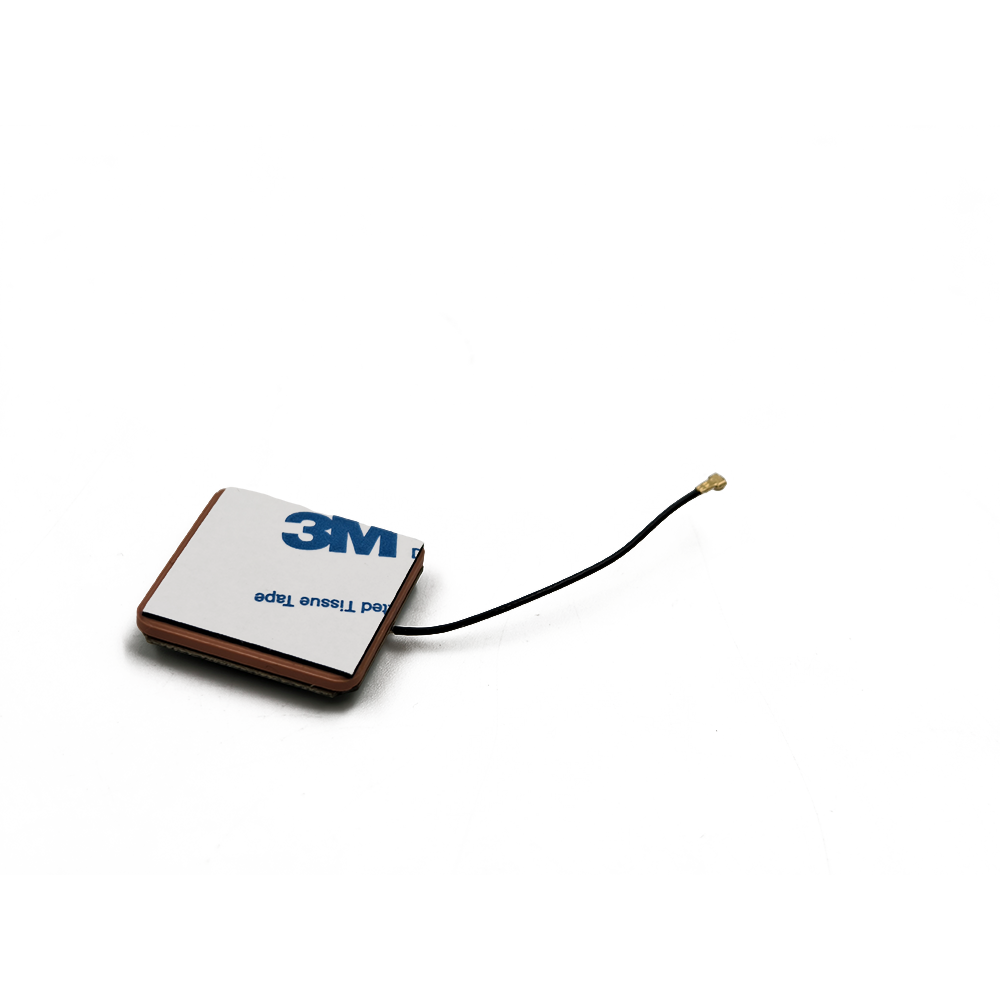
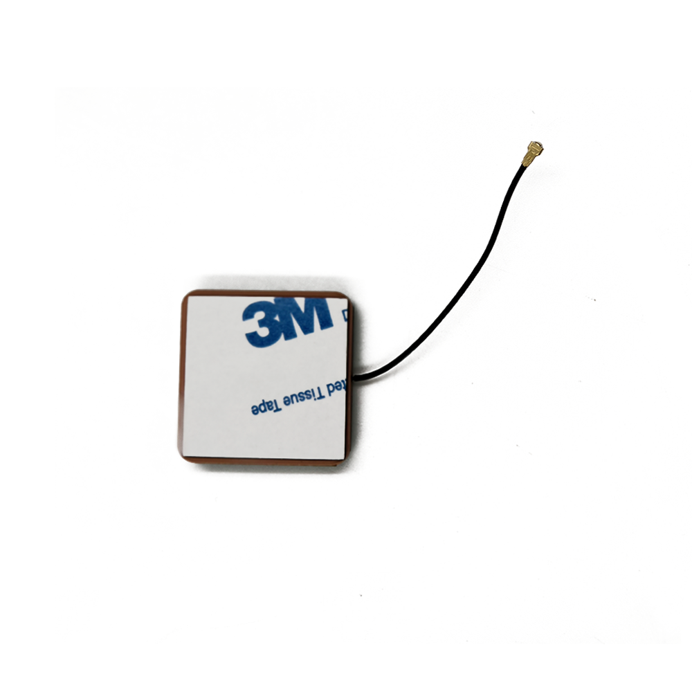
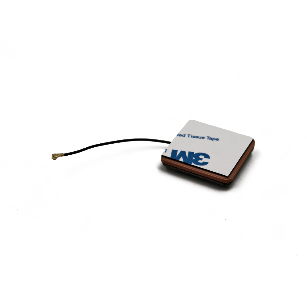
This is where the ceramic patch antenna, specifically engineered for RTK, comes into play. A patch antenna is a type of radio antenna that is flat, typically square or rectangular, and consists of a metallic patch mounted over a larger ground plane. When this design is fabricated on a ceramic substrate, remarkable properties emerge. Ceramics, such as barium strontium titanate, possess a very high dielectric constant (εr). This allows the electromagnetic waves to be concentrated within the material, enabling the antenna to be made significantly smaller than if it were built on a standard fiberglass (FR4) substrate—a crucial advantage for modern compact devices.
The "low-power" designation is equally critical. Traditional high-precision surveying antennas are often large, heavy, and require external power for built-in low-noise amplifiers (LNAs). The new generation of ceramic patch antennas integrates highly efficient LNAs that provide the necessary gain to overcome cable loss and boost the weak satellite signals to a usable level for the receiver, all while drawing minimal electrical current. This makes them ideal for battery-operated devices like drones, handheld mapping units, agricultural sensors, and autonomous robotics.
The convergence of these three attributes—high precision (RTK-ready), miniaturization (ceramic substrate), and energy efficiency (low-power LNA)—defines this antenna category. It is no longer a niche component but a foundational technology bridging the gap between the theoretical accuracy of RTK and its practical, mass-market deployment. From guiding agricultural machinery along sub-inch swaths to enabling a drone to hold its position steadily in high winds, the low-power ceramic RTK patch antenna is the unsung hero, providing the stable, clean, and reliable signal that makes modern precision not just possible, but ubiquitous.
Its development represents a triumph of materials science, electromagnetic engineering, and industrial design, packaging world-class performance into a form factor that can be seamlessly embedded into the next generation of autonomous and connected systems.
The exceptional performance of a low-power ceramic RTK patch antenna is not accidental; it is the result of meticulous design choices and sophisticated manufacturing processes. Every layer, material, and geometric feature is optimized to achieve a singular goal: to receive multiple GNSS satellite signals (GPS, GLONASS, Galileo, BeiDou) with extreme phase stability and minimal error. Deconstructing its architecture reveals the engineering brilliance within this seemingly simple component.
1. The Ceramic Substrate: The Foundation
The core of the antenna is the ceramic substrate. Unlike common PCB materials like FR4 (εr ~4.4), advanced ceramics have a very high dielectric constant, typically ranging from 20 to over 90. This is the most critical design parameter. A high εr reduces the wavelength of the electromagnetic wave within the material (λ = λ₀ / √εr). Since the size of the radiating patch is proportional to the wavelength, a high dielectric constant allows for a dramatically smaller antenna for a given frequency. This is the primary driver behind miniaturization.
However, a higher εr also brings challenges: it can lead to narrower bandwidth and increased surface wave losses, which can reduce efficiency. Engineers must therefore strike a precise balance between size, bandwidth, and efficiency by selecting a ceramic with the optimal εr and a low loss tangent (tan δ), which quantifies signal dissipation within the material.
2. The Radiating Patch: The Resonator
On top of the ceramic substrate, a thin layer of silver or other conductive material is printed or fired to form the radiating patch element. Its shape is predominantly square or rectangular, but its geometry is carefully calculated. The length (L) of the patch is slightly less than half the wavelength in the dielectric (λ/2) and determines the resonant frequency. Modern RTK antennas are almost always multi-band, designed to receive signals from multiple GNSS frequency bands (e.g., L1, L2, L5). This is achieved through sophisticated patch designs:
Stacked Patches: Using multiple ceramic layers with patches of different sizes stacked on top of each other, each tuned to a specific frequency band.
Slotted Patches: Cutting precise slots or grooves into a single patch. These slots alter the current paths on the patch, creating multiple resonant modes for different frequencies.
The symmetry and precision of the patch are vital for maintaining a consistent phase center.
Beneath the ceramic substrate lies a continuous metal ground plane. It acts as an electrical mirror, preventing radiation from propagating backwards and directing the antenna's energy into a hemispherical pattern towards the sky. Its size and integrity are crucial. A larger ground plane generally improves the antenna's front-to-back ratio and gain pattern but conflicts with the goal of miniaturization. For embedded applications, the device's own PCB is often designed to act as an extended ground plane for the antenna module.
4. The Low-Noise Amplifier (LNA): The Signal Booster
Integrated directly into the antenna assembly or mounted immediately beneath it is the LNA. This active component is what makes the antenna "low-power." Its job is to amplify the extremely weak signals from satellites (often below -130 dBm) before they travel through a cable to the receiver, thereby overcoming the signal degradation caused by cable loss. Key features of this LNA include:
High Gain (typically 26-40 dB): To make the signals strong and clear.
Low Noise Figure (<1.5 dB): This is paramount. The LNA must add as little inherent electronic noise as possible to avoid obscuring the already faint satellite signals.
Low Power Consumption: Often drawing only 5-20 mA at 3.3V, making it suitable for battery-powered devices.
Filtering: Built-in band-pass filtering to reject out-of-band interference from cellular, WiFi, or other RF sources.
5. The Radome and Shielding: The Protector
The entire assembly is encapsulated by a radome—a protective cover typically made of plastic. Its material is chosen for its minimal effect on RF signals (low dielectric constant). Furthermore, a metal shield or ferrite ring is often employed to suppress common-mode currents—unwanted currents that can flow on the outside of the coaxial cable shield, which act as an unintended part of the antenna and destabilize the phase center.
6. The Phase Center: The Virtual Point
The most critical concept in RTK antenna design is the Phase Center. It is the hypothetical point from which the transmitted or received radio wave appears to emanate. For RTK to work, this point must remain absolutely stable; it cannot move as the satellite moves across the sky (a phenomenon called Phase Center Variation, or PCV). High-quality RTK antennas undergo rigorous robotic calibration to map their PCV across all angles and frequencies. These PCV corrections can then be applied in the rover's firmware to virtually eliminate this source of error, a feature that truly separates professional RTK antennas from consumer-grade ones.
In summary, the construction of a low-power ceramic RTK patch antenna is a complex interplay of materials science, electromagnetic theory, and electronic engineering. Every layer, from the high-εr ceramic to the precisely printed patch, the robust ground plane, and the ultra-low-noise amplifier, works in concert to transform it from a simple receiver into a stable and reliable source of precision geospatial data.
The operation of a low-power ceramic RTK patch antenna is a elegant demonstration of electromagnetic physics, electronic amplification, and error mitigation. Its primary function is not just to "hear" GNSS signals, but to do so with such fidelity that the most minute details of the satellite's carrier wave phase can be measured without corruption. Understanding this process requires delving into how it interacts with incoming radio waves.
1. Fundamental Radiation Mechanism: Resonance
A patch antenna is a resonant cavity. The metal patch and the ground plane form two conducting surfaces, with the ceramic substrate acting as the dielectric insulator between them. When an electromagnetic wave from a satellite, oscillating at a specific frequency (e.g., 1575.42 MHz for GPS L1), impinges upon this structure, it induces an alternating current on the surface of the patch.
If the physical length of the patch is correct (approximately half the wavelength within the dielectric), it creates a standing wave of current. This resonance causes the antenna to efficiently couple energy from the passing radio wave into a guided electrical signal within the antenna's feed line. The ceramic substrate's high dielectric constant is crucial here, as it confines the electromagnetic fields primarily within the ceramic itself, reducing energy loss and allowing the antenna to be small yet effective.
2. Capturing the Right-Hand Circularly Polarized (RHCP) Signal
GNSS satellites transmit signals that are Right-Hand Circularly Polarized. This means the electric field of the radio wave rotates clockwise as it travels towards the antenna. A simple straight wire antenna is linearly polarized and would be poorly matched to this signal, leading to significant signal loss as the polarization misaligns. The patch antenna is uniquely suited to receive RHCP signals.
This is achieved by feeding the antenna at two points on the patch with a 90-degree phase difference between them. This dual feed, or a single feed with asymmetric perturbations (like notches or tabs), excites two orthogonal resonant modes on the patch. These modes, equal in amplitude but 90 degrees out of phase, combine in the far field to create the desired RHCP radiation pattern. This design efficiently rejects left-hand circularly polarized (LHCP) waves, which are typically created by multipath reflections (signals bouncing off the ground or buildings), thus providing inherent multipath suppression.
3. The Role of the Low-Noise Amplifier (LNA)
The currents induced on the patch are incredibly weak after traveling over 20,000 km from space. The LNA performs the first and most critical stage of amplification. Its low noise figure is essential because the signal-to-noise ratio (SNR) is paramount. Any noise introduced by the amplifier at this early stage is amplified by all subsequent stages in the receiver. By keeping its added noise extremely low, the LNA preserves the integrity of the original signal, allowing the receiver to lock onto and track the satellites even in challenging environments. The amplified signal is then sent via a coaxial cable to the GNSS receiver module for processing.
4. Enabling Phase-Based RTK Positioning
The antenna's ultimate purpose is to enable carrier-phase-based positioning. While consumer GPS uses the code (the digital message) in the signal for meter-level accuracy, RTK uses the phase of the carrier wave itself—a signal with a wavelength of just 19 cm for GPS L1. Measuring the phase difference to a fraction of a wavelength is what enables centimeter accuracy.
The antenna must provide a stable and precise phase reference. This is why Phase Center Variation (PCV) is so detrimental. If the antenna's apparent phase center moves when a satellite signal arrives from a low angle versus a high angle, the measured phase will be incorrect, introducing error into the RTK solution. The careful design of the patch, ground plane, and feed system, along with factory calibration, all work to minimize PCV. The consistent electrical properties of the ceramic substrate are key to this stability.
5. Multi-Band Operation
Modern RTK requires reception of multiple frequency bands (e.g., L1, L2, L5) to perform advanced error correction, particularly for neutralizing the ionospheric delay—a major source of error where the Earth's atmosphere slows down and bends GNSS signals. A multi-band ceramic patch antenna uses techniques like stacked patches to create separate resonant cavities within the same footprint. A larger patch lower in the stack resonates at a lower frequency (e.g., L2), while a smaller patch on top resonates at a higher frequency (e.g., L1). Each band has its own feed point or a shared feed that excites all resonances simultaneously.
In essence, the antenna works by acting as a highly selective, resonant filter for space-borne RHCP signals. It converts these faint radio waves into clean, amplified electrical signals while actively rejecting noise and multipath interference. Its stable phase response transforms it from a mere receiver into a precision measurement instrument, providing the raw data that allows the RTK engine to compute a position with astonishing accuracy. It is the unwavering foundation upon which the entire edifice of RTK positioning is built.
The adoption of low-power ceramic RTK patch antennas is a testament to their profound advantages over alternative designs. However, like any technology, they are not without their compromises and challenges. A clear-eyed evaluation of both sides is essential for engineers and system integrators to deploy them effectively.
Advantages:
Miniaturization and Form Factor: This is their most apparent advantage. The high dielectric constant of ceramics allows for a radical reduction in size compared to traditional antennas like quadrifilar helices (QFH) or larger patch antennas on FR4 substrates. This enables their integration into sleek drones, handheld devices, wearables, and IoT sensors where space is at a premium.
Low Power Consumption: The integrated LNAs are designed for extreme efficiency, often consuming less than 100mW of power. This is a critical enabler for the entire ecosystem of portable and autonomous systems. A surveyor can work all day without changing batteries, a drone can maximize its flight time, and a remote soil sensor can operate for years on a single battery.
Excellent Multipath Rejection: Their inherent design for receiving RHCP signals gives them a natural immunity to LHCP signals, which are predominantly generated by signals reflecting off surfaces. This directly translates to more reliable positioning in urban canyons, under tree cover, and near buildings—environments that traditionally plague GNSS accuracy.
High Phase Center Stability: While all antennas have some PCV, high-quality ceramic RTK patches are designed and calibrated to minimize it. This stability is the non-negotiable prerequisite for high-integrity RTK and PPP (Precise Point Positioning) solutions. It ensures that measurements are consistent and reliable, regardless of the satellite constellation geometry.
Ruggedness and Reliability: The solid-state construction, with a ceramic base and protective radome, lacks moving parts and is highly resistant to vibration, shock, and corrosion. This makes them ideal for harsh environments like agriculture, construction, and marine applications. They are also less susceptible to damage from handling or environmental factors than antennas with external elements.
Cost-Effectiveness at Scale: While the initial R&D and calibration costs are high, the manufacturing process for ceramic patch antennas is highly automatable and suitable for mass production. This has driven down costs significantly, making centimeter-accurate positioning accessible to new markets far beyond traditional surveying.
Challenges and Considerations:
Narrow Bandwidth: The same high dielectric constant that enables miniaturization also inherently limits the antenna's bandwidth. While clever design with stacked or slotted patches can overcome this to cover necessary GNSS bands, it remains a fundamental constraint. It can make the antenna more sensitive to manufacturing tolerances and less suitable for applications requiring very wide bandwidths beyond GNSS.
Temperature Sensitivity: The dielectric constant of ceramic materials can vary with temperature. This thermal drift can cause slight shifts in the antenna's resonant frequency and, more critically, its phase center. For the most demanding geodetic applications, this requires careful characterization and sometimes active temperature compensation or the use of more stable (and expensive) ceramic compounds.
Ground Plane Dependence: While they can function alone, their performance—particularly the gain pattern and axial ratio (a measure of how pure the circular polarization is)—is influenced by the size of the ground plane they are mounted on. Integrating them into a small device without a sufficient ground plane can degrade performance, necessitating careful system-level design.
Performance at Low Elevation Angles: Achieving good gain and a consistent phase center for satellites near the horizon is challenging for any antenna. While ceramic patches reject multipath well, their gain pattern can naturally roll off at low angles. Designers must make a trade-off: strongly suppressing low-angle signals (which are noisier) to fight multipath, or trying to receive them for better satellite geometry in obstructed environments.
Cost and Complexity of Calibration: To achieve geodetic-grade performance, each antenna design (not each individual antenna) must have its Phase Center Variation (PCV) meticulously mapped in an anechoic chamber using robotic arms. This calibration process is time-consuming, expensive, and requires highly specialized facilities. This cost is baked into the price of high-end antennas.
Susceptibility to Interference: Their wide view of the sky makes them susceptible to RF interference (jamming and spoofing), like all GNSS antennas. While the LNA includes filtering, sophisticated interference requires additional external mitigation techniques.
In conclusion, the advantages of low-power ceramic RTK patch antennas—size, power efficiency, and performance—overwhelmingly outweigh their challenges for the vast majority of modern applications. The key to success lies in understanding these challenges and addressing them through thoughtful design, proper integration, and selecting an antenna whose calibrated performance matches the accuracy requirements of the end application.
The unique blend of precision, size, and efficiency offered by low-power ceramic RTK patch antennas has shattered the barriers to entry for high-accuracy positioning. They have moved RTK from a specialized tool used by surveyors on tripods to an embedded technology powering a revolution across diverse industries. The applications are vast and growing, and the future trends point toward even deeper integration.
Current Applications:
Precision Agriculture: This is one of the largest markets. RTK-guided tractors and implements automate planting, spraying, and harvesting with centimeter accuracy, eliminating overlaps and gaps to save fuel, seed, and fertilizer. Autonomous rovers equipped with these antennas perform soil sampling and crop scouting.
Unmanned Aerial Vehicles (Drones): Drones for mapping, surveying, and infrastructure inspection rely on these antennas for two critical functions: providing a precise location for each captured photograph (enabling highly accurate photogrammetric models without ground control points) and enabling precise navigation and hover stability, even in windy conditions, for tasks like LiDAR scanning.
Robotics and Autonomous Systems: From warehouse logistics robots navigating dynamic environments to lawn mowers and last-mile delivery robots operating on sidewalks, these antennas provide the reliable absolute positioning that complements onboard sensors (LiDAR, cameras, odometry). They are a key sensor for any machine that needs to understand its place in the world.
Advanced Driver-Assistance Systems (ADAS) and Autonomous Vehicles: While safety-critical automotive systems use a fusion of many sensors, GNSS with RTK correction provides the indispensable global context—pinpointing the vehicle's lane on a high-definition map. This is crucial for validating the vehicle's location and planning maneuvers ahead of what the cameras and radar can see.
Construction and Machine Control: Bulldozers, graders, and excavators use RTK systems to guide blades and buckets to the exact design grade without the need for traditional stakes and strings. This increases speed, reduces rework, and improves safety. The ruggedness of ceramic antennas makes them ideal for this harsh vibration-heavy environment.
Marine and Hydrographic Survey: On boats and unmanned surface vessels (USVs), these antennas provide precise positioning for mapping seafloors, locating underwater structures, and navigating dredging operations.
Geospatial and Surveying: While traditional surveyors still use larger antennas on poles, the miniaturization has led to the proliferation of handheld RTK receivers for GIS data collection, asset mapping, and utilities location, bringing centimeter-accuracy into the palm of a hand.
Future Trends:
Deep Miniaturization (Chip Antennas): The trend is towards further integration, with RTK-capable antennas shrinking to the size of a surface-mount chip component. This will open up applications in consumer electronics, advanced wearables, and micro-mobility (e-scooters, e-bikes).
Tightly Coupled Integration (Antenna-in-Package): The next step is to integrate the antenna directly with the GNSS system-on-chip (SoC) or module into a single package. This minimizes transmission losses, reduces external noise, and simplifies the design process for OEMs, further driving down the size and cost of precision positioning.
AI-Enhanced Antennas: The integration of artificial intelligence at the hardware level could lead to "smart antennas." An AI processor could dynamically adapt the antenna's pattern to nullify interfering signals in real-time or optimize its characteristics for specific environments (e.g., urban vs. open sky), providing resilience against jamming and spoofing.
Multi-Function RF Convergence: A single ceramic substrate could host not only GNSS patches but also integrated antennas for cellular (4G/5G), WiFi, Bluetooth, and Iridium satellite communication. This would create a single, compact "communications hub" for devices that need both precise location and robust data links, which is essential for truly autonomous systems.
Ubiquitous PPP-RTK Services: As correction services like PPP-RTK become more globally available and affordable, the demand for antennas that can leverage them will soar. These antennas will need to be optimized for even higher stability to work with these precise but less dense correction networks.
Focus on Cybersecurity: As systems become more reliant on GNSS, protecting the signal integrity from malicious attacks will be paramount. Future antenna systems will likely incorporate more advanced signal authentication features directly at the point of reception.
The trajectory is clear: low-power ceramic RTK patch antennas will continue to become smaller, smarter, more integrated, and more resilient. They are evolving from a standalone component into a fundamental and ubiquitous enabling technology for the autonomous, interconnected world of the future.
6. Conclusion: The Bedrock of a Precise Future
The low-power ceramic RTK patch antenna is a paradigm-shifting technology. It represents a critical convergence point where the demanding performance requirements of geodetic science met the practical constraints of modern consumer and industrial design: miniaturization, power efficiency, and cost-effectiveness. This synthesis has democratized access to centimeter-accurate positioning, transforming it from a luxury available only to well-funded professionals into a standard feature available to innovators across countless fields.
As we have explored, its significance is multifaceted. From a technical standpoint, it is a marvel of engineering—leveraging the properties of advanced ceramics to shrink its form factor without sacrificing performance, integrating sophisticated electronics to boost signals while sipping power, and undergoing rigorous calibration to ensure its phase center remains a beacon of stability. This technical excellence directly enables its applied value. It is the silent, unassuming component that allows a farmer to optimize harvests, a drone to create a perfect 3D model, a robot to navigate a crowded warehouse, and a construction crew to build with unparalleled efficiency and safety.
The challenges it faces—narrow bandwidth, thermal sensitivity, and ground plane dependence—are not trivial, but they are well-defined and actively being addressed through continuous materials research and design innovation. The relentless trends in electronics towards greater integration and intelligence will only further mitigate these limitations, pushing the performance boundaries while simultaneously reducing size and cost.
Looking ahead, the role of this antenna technology will only grow more profound. It is a foundational pillar for the next wave of technological evolution: autonomy. Whether on the road, in the air, in the fields, or in our homes, machines that move and act with intelligence require an unwavering understanding of their absolute position in the world. The low-power ceramic RTK patch antenna provides this fundamental truth data. It is a key that is unlocking new levels of efficiency, safety, and capability across the global economy.
In conclusion, this antenna is far more than a simple receiver. It is an enabler, a catalyst, and a bedrock technology. By bridging the gap between the immense potential of satellite-based positioning and the real-world constraints of device design, it has firmly established itself as an indispensable component in building a more precise, efficient, and autonomous future.

 86 0755 2819 9597
Lucy Yang | lucy.y@toxutech.com
Nicole Li | nicole@toxutech.com
Dotty Zhao | sales04@toxutech.com
Global Business Director / Sales Team / Global Operations


 En
En Cn
Cn Korean
 Home >


