

-
Products -PCBA Manufacturing RF Connectors RF Cable Assemblys Embedded Antennas External Antennas Positioning Chips and Modules
RF Connectors

RF Cable Assemblys
Embedded Antennas
External Antennas
Positioning Chips and Modules


 Language


Language


Global Navigation Satellite Systems (GNSS) have become an integral part of modern technology, enabling precise positioning and navigation across various applications, from automotive navigation to agricultural machinery. Among the different GNSS technologies, Real-Time Kinematic (RTK) stands out for its ability to provide centimeter-level accuracy, making it indispensable in fields that require high precision, such as surveying, construction, and autonomous vehicles.
A crucial component of any GNSS RTK system is the antenna, which captures satellite signals and converts them into electrical signals for processing. Low-power GNSS RTK ceramic patch antennas have emerged as a popular choice due to their compact size, cost-effectiveness, and efficient performance. This overview will delve into the basics of these antennas, their importance, and their role in enhancing GNSS RTK systems.
What is a Ceramic Patch Antenna?
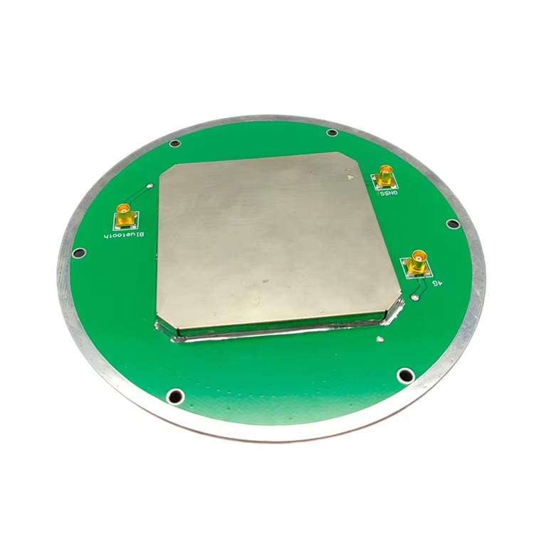
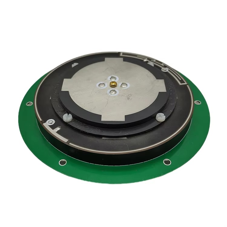
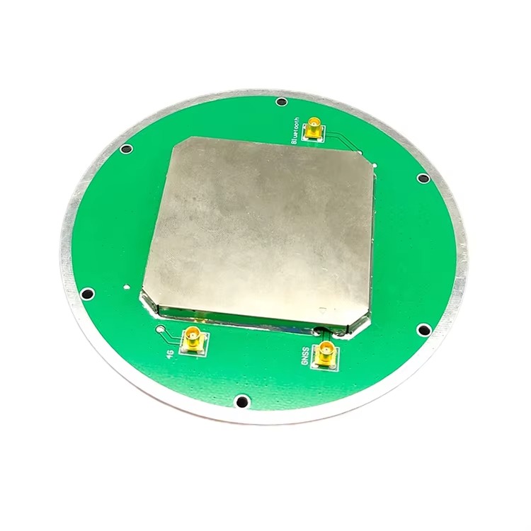
A ceramic patch antenna is a type of microstrip antenna that utilizes a ceramic substrate to achieve a compact and lightweight design. The antenna consists of a metallic patch printed on a ceramic dielectric material, which is then mounted on a ground plane. The ceramic material offers high dielectric constant and low loss tangent, which are essential for achieving efficient radiation and reception of electromagnetic waves at GNSS frequencies (typically around 1.2 GHz for GPS L1 and 1.5 GHz for Galileo E1).
Importance in GNSS RTK Systems
In GNSS RTK systems, achieving high accuracy relies heavily on the quality of the received satellite signals. Any loss or distortion in the signal can degrade the positioning accuracy. Ceramic patch antennas are designed to minimize such losses and provide a stable phase center, which is crucial for maintaining the integrity of the RTK corrections. Additionally, their low-power consumption makes them suitable for battery-operated devices, extending the operational life of portable GNSS RTK receivers.
Market Trends and Developments
The demand for low-power GNSS RTK ceramic patch antennas has been on the rise, driven by the proliferation of IoT devices, drones, and autonomous systems that require precise positioning capabilities. Manufacturers are continuously innovating to improve antenna performance, reduce size, and enhance durability. Advances in materials science and antenna design techniques are enabling the development of antennas that can operate across multiple GNSS frequency bands, further expanding their applicability.
Conclusion of Overview
Low-power GNSS RTK ceramic patch antennas play a vital role in enabling precise positioning and navigation in a wide range of applications. Their compact size, cost-effectiveness, and efficient performance make them an attractive choice for designers and engineers. As technology continues to evolve, these antennas are expected to become even more sophisticated, contributing to the advancement of GNSS RTK systems and their applications.
Introduction
The design and construction of low-power GNSS RTK ceramic patch antennas are critical to their performance and reliability. This section will explore the key considerations in antenna design, including substrate selection, patch geometry, feeding techniques, and ground plane design, as well as the manufacturing processes involved in producing these antennas.
Substrate Selection
The choice of substrate material is paramount in ceramic patch antenna design. The substrate must have a high dielectric constant to reduce the antenna size while maintaining efficient radiation. Additionally, it should exhibit a low loss tangent to minimize signal attenuation. Common ceramic materials used in GNSS antennas include alumina (Al2O3), zirconia (ZrO2), and various composite ceramics. Each material offers a trade-off between dielectric constant, loss tangent, and cost, and the selection depends on the specific application requirements.
Patch Geometry
The geometry of the metallic patch determines the antenna's resonant frequency, bandwidth, and radiation pattern. For GNSS applications, the patch is typically designed to resonate at the center frequency of the desired GNSS band. The patch shape can vary from simple squares and rectangles to more complex geometries like circles and ellipses, depending on the desired radiation characteristics. Advanced design techniques, such as fractal geometry, can be employed to achieve multi-band operation or improve bandwidth efficiency.
Feeding Techniques
The method used to feed electrical signals to the patch is crucial for antenna performance. Common feeding techniques include microstrip line feeding, coaxial probe feeding, and aperture coupling. Microstrip line feeding is simple and cost-effective but may introduce additional losses. Coaxial probe feeding offers better impedance matching but can be more challenging to manufacture. Aperture coupling provides isolation between the feed line and the patch, reducing spurious radiation and improving performance.
Ground Plane Design
The ground plane beneath the patch plays a vital role in determining the antenna's radiation pattern and impedance characteristics. A larger ground plane generally improves radiation efficiency but increases the overall antenna size. Designers must balance these factors to achieve the desired performance while maintaining a compact form factor. Additionally, the ground plane can be shaped or patterned to control the radiation pattern or reduce back radiation.
Manufacturing Processes
The manufacturing of low-power GNSS RTK ceramic patch antennas involves several steps, including substrate preparation, patch printing, assembly, and testing. Substrate preparation involves cutting the ceramic material to the desired size and shape, followed by surface treatment to improve adhesion. The metallic patch is then printed onto the substrate using techniques like screen printing or photolithography. The antenna is assembled by mounting it on a ground plane and connecting the feed line. Finally, the antenna undergoes rigorous testing to ensure it meets the specified performance criteria.
Conclusion of Design and Construction
The design and construction of low-power GNSS RTK ceramic patch antennas require careful consideration of substrate selection, patch geometry, feeding techniques, and ground plane design. By optimizing these parameters, designers can create antennas that offer efficient performance, compact size, and low power consumption. Advances in manufacturing processes continue to improve the quality and consistency of these antennas, making them suitable for a wide range of GNSS RTK applications.
Introduction
Understanding the working principles of low-power GNSS RTK ceramic patch antennas is essential for appreciating their role in GNSS RTK systems. This section will explain how these antennas receive and process satellite signals, the concept of phase center stability, and the importance of antenna calibration in achieving high accuracy.
Signal Reception and Processing
GNSS satellites transmit signals at specific frequencies, carrying information about their position and the time of transmission. When these signals reach the Earth's surface, they are captured by the GNSS antenna. In the case of a ceramic patch antenna, the metallic patch acts as a resonator, converting the incoming electromagnetic waves into electrical currents. These currents are then fed to the GNSS receiver through the feed line, where they are processed to extract the satellite's position and timing information.
Phase Center Stability
The phase center of an antenna is the point from which the electromagnetic waves appear to originate or terminate. In GNSS RTK systems, maintaining a stable phase center is crucial for achieving high accuracy. Any movement or variation in the phase center can introduce errors in the positioning calculations. Ceramic patch antennas are designed to have a stable phase center, even under varying environmental conditions, ensuring consistent performance in GNSS RTK applications.
Antenna Calibration
Antenna calibration is the process of determining the phase center offset and other antenna-related errors, such as group delay variations. This information is then used to correct the GNSS measurements, improving the overall positioning accuracy. Calibration is typically performed in an anechoic chamber using specialized equipment that can accurately measure the antenna's response to satellite signals. For low-power GNSS RTK ceramic patch antennas, calibration is essential to ensure they meet the stringent accuracy requirements of RTK systems.
Multi-Path Mitigation
Multi-path interference occurs when satellite signals reflect off surfaces like buildings or trees before reaching the antenna, causing errors in the positioning calculations. Ceramic patch antennas are designed to minimize multi-path effects by employing techniques like right-hand circular polarization (RHCP) and careful control of the radiation pattern. RHCP ensures that the antenna is more sensitive to directly arriving signals and less sensitive to reflected signals, reducing multi-path interference.
Environmental Considerations
The performance of low-power GNSS RTK ceramic patch antennas can be affected by environmental factors such as temperature, humidity, and vibration. Designers must consider these factors during the antenna design process to ensure reliable operation in various conditions. For example, the use of temperature-stable materials and robust construction techniques can help maintain antenna performance over a wide temperature range.
Conclusion of Working Principles
Low-power GNSS RTK ceramic patch antennas operate by receiving satellite signals, converting them into electrical currents, and feeding them to the GNSS receiver for processing. Maintaining a stable phase center, performing antenna calibration, mitigating multi-path interference, and considering environmental factors are all crucial for achieving high accuracy in GNSS RTK systems. By understanding these working principles, designers and engineers can optimize antenna performance for specific applications.
Introduction
Low-power GNSS RTK ceramic patch antennas offer several advantages over traditional antenna designs, making them a popular choice for many applications. However, they also face certain challenges that must be addressed to ensure reliable performance. This section will explore both the advantages and challenges of these antennas.
Advantages
Compact Size: Ceramic patch antennas are significantly smaller than traditional antenna designs, making them ideal for applications where space is limited, such as portable GNSS receivers and IoT devices.
Low Power Consumption: These antennas are designed to operate with minimal power, extending the battery life of portable devices and reducing energy costs in fixed installations.
Cost-Effective: The use of ceramic materials and advanced manufacturing techniques allows for cost-effective production of these antennas, making them accessible to a wide range of applications.
High Accuracy: By maintaining a stable phase center and minimizing multi-path interference, ceramic patch antennas contribute to the high accuracy of GNSS RTK systems.
Multi-Band Operation: Advances in antenna design enable ceramic patch antennas to operate across multiple GNSS frequency bands, improving flexibility and interoperability.
Challenges
Material Limitations: While ceramic materials offer high dielectric constants and low loss tangents, they can be brittle and susceptible to damage from mechanical stress or thermal shock.
Manufacturing Tolerances: Achieving precise manufacturing tolerances is crucial for maintaining antenna performance. Variations in substrate thickness, patch dimensions, or feeding techniques can introduce errors in the positioning calculations.
Environmental Sensitivity: The performance of ceramic patch antennas can be affected by environmental factors such as temperature, humidity, and vibration. Designers must carefully consider these factors during the antenna design process to ensure reliable operation.
Antenna Calibration Complexity: Accurate antenna calibration is essential for achieving high accuracy in GNSS RTK systems. However, the calibration process can be complex and time-consuming, requiring specialized equipment and expertise.
Signal Obstruction: In urban environments or areas with dense foliage, satellite signals can be obstructed, reducing the availability and accuracy of GNSS positioning. Ceramic patch antennas, like all GNSS antennas, are subject to these limitations.
Mitigation Strategies
To address these challenges, designers and engineers employ various strategies. For example, they may use robust construction techniques to improve the durability of ceramic patch antennas, implement advanced manufacturing processes to achieve precise tolerances, and incorporate environmental sensors to compensate for temperature and humidity variations. Additionally, the use of multi-constellation GNSS receivers and augmentation systems can help improve signal availability and accuracy in challenging environments.
Conclusion of Advantages and Challenges
Low-power GNSS RTK ceramic patch antennas offer several advantages, including compact size, low power consumption, cost-effectiveness, high accuracy, and multi-band operation. However, they also face challenges related to material limitations, manufacturing tolerances, environmental sensitivity, antenna calibration complexity, and signal obstruction. By employing mitigation strategies and continuous innovation, designers and engineers can overcome these challenges and further enhance the performance and reliability of these antennas.
Introduction
Low-power GNSS RTK ceramic patch antennas are used in a wide range of applications that require precise positioning and navigation. This section will explore some of the key applications of these antennas and discuss future trends that are expected to shape their development and adoption.
Key Applications
Automotive Navigation: Ceramic patch antennas are used in automotive navigation systems to provide accurate positioning information for drivers. With the rise of autonomous vehicles, the demand for high-precision GNSS RTK systems is expected to increase, driving the adoption of these antennas.
Agricultural Machinery: Precision agriculture relies on GNSS RTK systems to guide tractors and other machinery with centimeter-level accuracy. Ceramic patch antennas are well-suited for this application due to their compact size and low power consumption.
Surveying and Mapping: Surveyors use GNSS RTK systems to measure land features and create detailed maps. The high accuracy and reliability of ceramic patch antennas make them an ideal choice for this demanding application.
Unmanned Aerial Vehicles (UAVs): UAVs require precise positioning information for navigation, mapping, and inspection tasks. Ceramic patch antennas are used in UAV GNSS receivers to provide accurate and reliable positioning data.
IoT Devices: The proliferation of IoT devices that require location-based services is driving the demand for compact and low-power GNSS antennas. Ceramic patch antennas are well-positioned to meet this demand due to their small size and efficient performance.
Future Trends
Multi-Constellation and Multi-Band Operation: As more GNSS constellations become available, there is a growing need for antennas that can operate across multiple frequency bands. Future ceramic patch antennas are expected to support multiple GNSS constellations, improving positioning availability and accuracy.
Integration with Other Sensors: To further enhance positioning accuracy, ceramic patch antennas may be integrated with other sensors such as inertial measurement units (IMUs) and barometers. This integration can provide redundancy and improve performance in challenging environments.
Advanced Manufacturing Techniques: Advances in manufacturing techniques, such as 3D printing and nanotechnology, may enable the production of ceramic patch antennas with even smaller sizes and improved performance. These techniques could also reduce manufacturing costs, making these antennas more accessible to a wider range of applications.
Increased Use in Consumer Electronics: As consumer electronics devices like smartphones and wearables incorporate more location-based services, the demand for compact and low-power GNSS antennas is expected to increase. Ceramic patch antennas are well-suited for this market due to their small size and efficient performance.
Enhanced Security Features: With the growing concern over GNSS spoofing and jamming, future ceramic patch antennas may incorporate enhanced security features to detect and mitigate these threats. This could include the use of cryptographic techniques and advanced signal processing algorithms.
Conclusion of Applications and Future Trends
Low-power GNSS RTK ceramic patch antennas are used in a wide range of applications that require precise positioning and navigation. Future trends, such as multi-constellation and multi-band operation, integration with other sensors, advanced manufacturing techniques, increased use in consumer electronics, and enhanced security features, are expected to shape the development and adoption of these antennas. By staying abreast of these trends, designers and engineers can create antennas that meet the evolving needs of various industries and applications.
Conclusion
Summary of Key Points
Throughout this series, we have explored the overview, design and construction, working principles, advantages and challenges, applications, and future trends of low-power GNSS RTK ceramic patch antennas. These antennas play a crucial role in enabling precise positioning and navigation in a wide range of applications, from automotive navigation to agricultural machinery and IoT devices.
Importance in Modern Technology
The importance of low-power GNSS RTK ceramic patch antennas in modern technology cannot be overstated. Their compact size, low power consumption, cost-effectiveness, and efficient performance make them an attractive choice for designers and engineers. As technology continues to evolve, these antennas are expected to become even more sophisticated, contributing to the advancement of GNSS RTK systems and their applications.
Contribution to Precision and Efficiency
By providing accurate and reliable positioning information, low-power GNSS RTK ceramic patch antennas contribute to the precision and efficiency of various industries. In automotive navigation, they help drivers navigate unfamiliar roads with confidence. In agriculture, they enable precision farming practices that optimize crop yields and reduce environmental impact. In surveying and mapping, they provide the data needed to create detailed and accurate maps. And in IoT devices, they enable location-based services that enhance user experience and enable new applications.
Future Prospects
Looking ahead, the future prospects for low-power GNSS RTK ceramic patch antennas are bright. With the continued expansion of GNSS constellations, the integration of advanced manufacturing techniques, and the growing demand for location-based services, these antennas are poised to play an even more significant role in modern technology. Designers and engineers will continue to innovate, pushing the boundaries of what is possible and creating antennas that meet the evolving needs of various industries and applications.
Final Thoughts
In conclusion, low-power GNSS RTK ceramic patch antennas are a testament to the power of innovation and engineering. Their compact size, low power consumption, and efficient performance make them an indispensable component of modern GNSS RTK systems. As technology continues to advance, these antennas will remain at the forefront of precision positioning and navigation, contributing to the growth and development of various industries and applications.

 86 0755 2819 9597
Lucy Yang | lucy.y@toxutech.com
Nicole Li | nicole@toxutech.com
Dotty Zhao | sales04@toxutech.com
Global Business Director / Sales Team / Global Operations


 En
En Cn
Cn Korean
 Home >


