

-
Products -PCBA Manufacturing RF Connectors RF Cable Assemblys Embedded Antennas External Antennas Positioning Chips and Modules
RF Connectors

RF Cable Assemblys
Embedded Antennas
External Antennas
Positioning Chips and Modules


 Language


Language


The Global Positioning System (GPS) and other Global Navigation Satellite Systems (GNSS) like GLONASS, Galileo, and BeiDou have evolved from a specialized military technology into a ubiquitous utility underpinning modern civilization. From navigating city streets to synchronizing financial networks, GNSS provides the critical infrastructure of location and time. However, standard, single-frequency GPS receivers, like those in smartphones and car navigation systems, offer accuracy only in the range of 3 to 5 meters under open skies. This level of precision is sufficient for guiding a person to a restaurant but is utterly inadequate for applications requiring centimeter-level accuracy, such as autonomous vehicle guidance, precision agriculture, or land surveying.
This need for high precision gave rise to Real-Time Kinematic (RTK) technology. RTK is a sophisticated technique that uses carrier-phase measurements from GNSS signals to achieve positional accuracy within centimeters. It works by using a single base station receiver at a known, fixed location to calculate the error in the satellite signals and then transmitting these error corrections to one or more rover receivers in the field. By applying these corrections in real-time, the rover can compute its position with extreme accuracy. The entire chain of this high-precision operation is only as strong as its weakest link. One of the most critical, yet often overlooked, components in this chain is the antenna.
The antenna is the gateway between the satellite constellation thousands of kilometers away and the sensitive electronics of the receiver. Its primary function is to efficiently capture the incredibly weak right-hand circularly polarized (RHCP) radio signals broadcast by GNSS satellites. The performance of the antenna directly dictates the quality of the signals passed to the receiver and, consequently, the accuracy and reliability of the final position solution. For decades, high-precision GNSS antennas were large, heavy, and prohibitively expensive, often costing thousands of dollars. They were constructed from machined metal and were the domain of professional surveyors and scientific institutions.
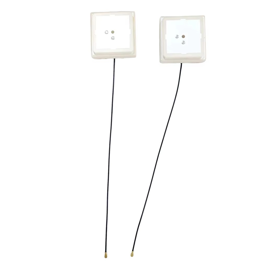
The advent of the low-cost GPS RTK ceramic patch antenna represents a revolutionary democratization of this high-precision technology. This device is a compact, flat, and inexpensive antenna built on a ceramic substrate that is capable of supporting the rigorous demands of RTK and other carrier-phase-based positioning methods. Its development has been driven by advancements in materials science, manufacturing processes, and electronic design, coinciding with the explosive growth of new mass-market applications like consumer drones, robotics, and autonomous machinery.
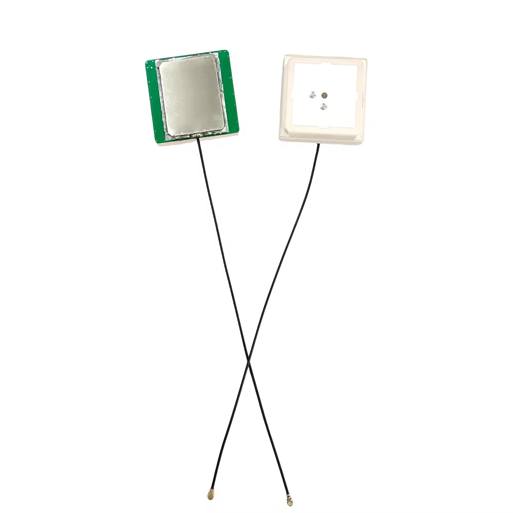
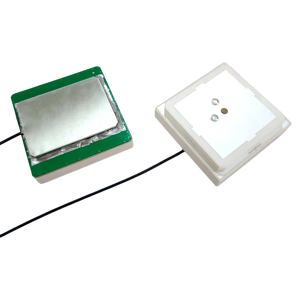
A ceramic patch antenna is a type of microstrip antenna. Its core component is a radiating element, or "patch," typically made of a conductive material like silver or copper, which is printed or etched onto a dielectric substrate—in this case, a specially formulated ceramic material. This patch is suspended over a ground plane, and the entire assembly is usually housed in a protective plastic shell. The ceramic material is chosen for its specific electrical properties that allow the antenna to be both highly efficient and physically small.
The "low-cost" aspect is not merely about price; it signifies a fundamental shift in accessibility. By reducing the cost of a critical RTK component from thousands to tens of dollars, these antennas have broken down the barriers to entry for high-precision positioning. They have enabled a new wave of innovation, allowing startups, university research labs, and hobbyists to experiment with and deploy technologies that were previously the exclusive purview of well-funded corporations or government agencies.
However, this cost reduction does not come without engineering trade-offs. While their performance can be remarkably good, low-cost ceramic antennas generally do not match the ultimate performance of their high-end counterparts in every metric. They may have slightly lower gain, be more susceptible to multipath errors (signals reflected from the ground or buildings), or have a less perfectly defined phase center. The art and science of designing these antennas lie in optimizing these trade-offs to deliver a level of performance that is "good enough" for a vast array of new applications while maintaining a radically lower price point.
In summary, the low-cost GPS RTK ceramic patch antenna is a key enabler of the high-precision positioning revolution. It is a marvel of modern engineering that packages complex electromagnetic principles into a small, affordable, and robust package. By providing a reliable window to the GNSS satellites, it forms the foundational sensor upon which a new generation of autonomous and intelligent systems is being built, transforming industries and pushing the boundaries of what is possible with location technology.
To appreciate the role of a ceramic patch antenna in an RTK system, one must understand the fundamental physics of how it operates and the nature of the signals it is designed to capture. Its working principle is a practical application of electromagnetic theory, tailored to the unique demands of satellite-based positioning.
1. Basic Microstrip Antenna Operation:
A patch antenna is a resonant cavity. The patch conductor and the ground plane form the two walls of this cavity, with the ceramic substrate acting as the dielectric filler. When RF energy is fed to the patch (in transmission mode; reception is the reciprocal process), it excites electromagnetic waves within this cavity. The dimensions of the patch, specifically its length (L), are designed to be approximately half of the wavelength within the dielectric material at the target frequency.
The wavelength in the dielectric (λ_d) is given by λ_d = λ_0 / √εᵣ, where λ_0 is the free-space wavelength and εᵣ is the dielectric constant of the substrate. This is the key to its small size. For a GPS L1 signal (1575.42 MHz, λ_0 ≈ 19 cm), a substrate with εᵣ = 36 would reduce the required patch length to about λ_0 / (2 * √36) = 19cm / 12 = 1.58 cm. This miniaturization is what makes the compact ceramic antenna possible.
The patch radiates from the fringing fields that extend beyond its edges. The radiation pattern is broad, perpendicular to the plane of the patch, making it ideal for receiving signals from satellites across the entire sky.
2. Receiving GNSS Signals:
GNSS signals are incredibly weak by the time they travel over 20,000 km to reach the Earth's surface. They are often described as being "below the noise floor," meaning their power is lower than the inherent thermal noise in the environment and the receiver's electronics. They are spread-spectrum signals, using a technique called Code Division Multiple Access (CDMA), which allows all satellites to broadcast on the same frequency without interference. The receiver uses correlation techniques to de-spread the signal and pull it out of the noise.
The antenna's job is to collect as much of this weak signal power as possible. Its gain is a measure of its effectiveness in doing so in a specific direction. The ceramic patch is designed to have peak gain towards the zenith (straight up) and good gain down to low elevation angles (5-10 degrees above the horizon), maximizing the number of satellites it can "see."
3. The Critical Role in RTK and Carrier-Phase Tracking:
Standard GPS positioning uses the C/A code, which has a wavelength of about 300 meters. Measuring the code phase gives a rough distance measurement, leading to meter-level accuracy.
RTK, however, uses the carrier phase of the signal itself. The L1 carrier wave has a wavelength of only 19 centimeters. The receiver can measure the phase of this carrier wave to a small fraction of a wavelength, potentially enabling millimeter-level precision. However, the problem is that the carrier phase is ambiguous—the receiver can measure the fractional wavelength but doesn't know the integer number of full wavelengths between the satellite and itself (the "integer ambiguity").
The RTK process involves resolving this integer ambiguity. The base station, at a known location, calculates what the carrier phase measurement should be for each satellite. It then sends the difference between this calculated value and its actual measured value to the rover. The rover compares this correction to its own measurements. By processing differences between satellites and between receivers, the integer ambiguities can be resolved mathematically, yielding a ultra-precise vector between the base and the rover.
4. How Antenna Performance Directly Affects RTK:
This is where the antenna's characteristics become paramount:
Phase Center Stability: Any movement of the antenna's electrical phase center, as seen from different satellite angles, directly introduces error into the carrier-phase measurement. If the phase center moves by 2 mm for a satellite low on the horizon compared to one overhead, that 2 mm error will be embedded in the measurement, degrading the solution. A high-quality antenna minimizes this Phase Center Variation (PCV). Low-cost antennas must have their PCV characterized so the receiver firmware can apply corrections, a process called antenna calibration.
Multipath Rejection: A reflected signal takes a longer path to the antenna than the direct line-of-sight signal. This creates an error in the measured distance. Since the antenna is the first point of contact, its ability to reject these reflected signals is crucial. This is achieved through its radiation pattern (low gain toward the horizon and ground) and its polarization purity (rejecting LHCP reflections). A poor antenna will allow more multipath energy into the receiver, making it harder to resolve integer ambiguities and causing "jumps" in the precise position.
Bandwidth and Group Delay: To track signals on multiple frequencies, the antenna must have a flat response across all required bands. Variations in its performance across the band can cause group delay, where different frequency components of the signal arrive at the receiver input at slightly different times. This distorts the signal and can degrade the accuracy of the code and carrier-phase measurements.
In essence, the ceramic patch antenna is not a passive component; it is an active participant in the measurement process. Its physics directly influences the most critical data the RTK engine uses: the timing of the electromagnetic waves arriving from space. A well-designed low-cost antenna provides a stable, clean, and predictable platform for these measurements, enabling the complex mathematics of RTK to converge reliably on a centimeter-accurate solution.
The proliferation of low-cost ceramic patch antennas has been a game-changer, but like any technology born from cost-performance trade-offs, it presents a distinct set of advantages and challenges that engineers and users must navigate.
Advantages:
Dramatic Cost Reduction: This is the most obvious and impactful advantage. Reducing the cost of an RTK-grade antenna from over $1,000 to well under $100 (often $10-$50 in volume) has democratized high-precision positioning. It has enabled its integration into cost-sensitive applications previously unimaginable, from consumer products to large-scale IoT deployments.
Small Form Factor and Low Profile: The use of high-dielectric ceramic materials allows for a very compact design. These antennas are typically only a few centimeters square and a centimeter thick. This small size is essential for integration into modern devices like drones, smartphones, agricultural sensors, and wearable technology, where space is at a premium.
Ruggedness and Reliability: The solid ceramic substrate and plastic housing create a monolithic structure that is highly resistant to vibration, shock, and physical damage. Unlike larger antennas with separate elements, there are no loose parts to break. They are also easily sealed against moisture and dust (e.g., IP67 rating), making them suitable for harsh outdoor and industrial environments.
Ease of Integration and Mass Production: These antennas are designed for surface mounting (SMD) onto a PCB, just like any other electronic component. They can be automatically picked and placed by robots during assembly, drastically reducing manufacturing complexity and cost compared to mounting and wiring a larger external antenna. Their standardized footprint and connectorized options simplify the design-in process for engineers.
Good Performance for the Price: While not matching the ultimate performance of geodetic-grade antennas, modern low-cost ceramics offer surprisingly capable performance. They provide sufficient gain, acceptable axial ratio, and adequate multipath rejection for a wide range of professional and commercial applications where sub-decimeter accuracy is acceptable.
Challenges and Limitations:
Phase Center Variation (PCV): This is the most significant technical challenge. The phase center in a low-cost antenna is less stable than in a premium antenna. Its location can shift several millimeters depending on the elevation and azimuth of the satellite. This variation introduces errors into the carrier-phase measurements that are not easily corrected without a precise, individualized antenna calibration model. While generic models for common antennas exist, they cannot correct for unit-to-unit variations, potentially limiting ultimate accuracy.
Limited Bandwidth and Multi-Frequency Performance: Designing a small, ceramic-based antenna to cover all GNSS bands (L1, L2, L5, E1, E5, B1, B3, etc.) with uniform performance is extremely difficult. Often, performance is optimized for the primary L1 band, with degraded performance (lower gain, higher axial ratio) on secondary bands. This can impact the robustness and convergence time of multi-frequency RTK engines, which rely on signals from multiple bands to quickly resolve integer ambiguities.
Susceptibility to Multipath: Despite design efforts, their small ground plane and inherent design make them more susceptible to multipath signals compared to larger, choke-ring antennas. Multipath from below or from the sides can more easily couple into the antenna, especially when mounted on a vehicle or near structures. This can cause accuracy degradation in challenging urban or canopy environments.
Ground Plane Dependence: The performance of a patch antenna is highly dependent on the size and quality of the ground plane it is mounted on. The user's PCB itself often acts as the ground plane. If this PCB is too small, or if it has cuts and slots, the antenna's radiation pattern can be severely distorted, its gain reduced, and its phase center made even less stable. This places an additional design burden on the system integrator.
Performance Consistency and Quality Control: In the drive for lowest cost, manufacturing tolerances can lead to performance variations from one antenna unit to the next. Slight variations in ceramic composition, printing alignment, or soldering can affect the resonant frequency, impedance matching, and PCV. While high-volume manufacturers test for basic parameters like Return Loss (VSWR), full pattern and phase characterization of every unit is economically impossible, leading to potential performance outliers.
Navigating the Trade-offs:
The key to successfully using these antennas is understanding these trade-offs and designing the system accordingly. For applications where the highest possible accuracy (sub-centimeter) is required, or where operation must occur in severe multipath environments, a more expensive, survey-grade antenna remains the best choice.
However, for the vast majority of new applications—automated guided vehicles (AGVs) in warehouses, consumer mapping drones, precision agriculture sprayers, and machine control—the advantages of low cost, small size, and robustness far outweigh the limitations. System designers can often mitigate these challenges through other means: using multi-frequency receivers to improve robustness, implementing advanced filtering algorithms to suppress multipath, and ensuring a proper ground plane is provided in the product design. The low-cost ceramic patch antenna is therefore not a perfect replacement, but a powerful new tool that has opened up a new design space for innovative and accessible high-precision navigation.
The availability of low-cost, high-precision positioning components has acted as a catalyst, spawning a new ecosystem of applications that were either technically impossible or economically unviable just a decade ago. The ceramic patch antenna is at the core of this transformation, serving as the essential sensor enabling centimeter-aware autonomy.
Current Applications:
Precision Agriculture: This is one of the largest and most established markets. RTK guidance systems on tractors and harvesters enable automated steering with centimeter accuracy, reducing overlap and gaps in planting, spraying, and harvesting. This saves fuel, seeds, fertilizer, and time, boosting farm efficiency and yield. Low-cost antennas are also integrated into "spot-spraying" robots that identify and spray individual weeds, dramatically reducing herbicide use.
Unmanned Aerial Vehicles (Drones): Drones for surveying, mapping, and agricultural spraying rely on RTK for precise positioning. This allows them to fly accurate pre-programmed flight paths, create highly accurate orthomosaics and 3D models without ground control points, and precisely target spray applications. The small size and weight of ceramic antennas are critical for drone payload constraints.
Robotics and Autonomous Guided Vehicles (AGVs): From warehouse logistics robots to last-mile delivery vehicles and lawn mowers, autonomy requires precise knowledge of location. Low-cost RTK provides a global absolute position reference that complements other sensors like LiDAR, cameras, and odometry. It allows robots to navigate complex outdoor and semi-structured indoor environments reliably.
Urban Mobility and Automotive: While full autonomy requires a sensor fusion approach, RTK is being integrated into Advanced Driver-Assistance Systems (ADAS) and prototyping for autonomous vehicles. It provides a highly reliable and absolute positioning layer that is immune to the drift that affects inertial navigation systems (INS) over time. It's also used in vehicle-to-everything (V2X) communication for precise location-aware safety messages.
Construction and Machine Control: Bulldozers, graders, and excavators can be equipped with RTK systems for grade control, allowing them to dig and move earth to precise design specifications without traditional survey stakes. This increases speed, accuracy, and safety on construction sites.
Consumer and Geofencing Applications: Although less common, high-precision GPS is trickling into consumer devices for enhanced photography geotagging, augmented reality (AR) experiences, and strict geofencing for personal drones or security systems.
Future Trends:
Tighter Integration with Inertial Navigation Systems (INS): The future lies in deeply fused RTK/INS solutions. The RTK provides absolute accuracy but can suffer from signal outages (e.g., in tunnels or urban canyons). The INS (IMU + processor) provides a continuous, high-rate position, velocity, and attitude solution but drifts over time. A low-cost, deeply integrated RTK-INS system, often built on a single board, will become the standard positioning engine for autonomy, with the ceramic antenna being a key component on the board.
AI-Enhanced Multipath Mitigation: Advanced algorithms and even AI are being developed to better identify and filter out multipath signals at the receiver level. This will help compensate for one of the inherent weaknesses of low-cost antennas, making them more robust in challenging environments and narrowing the performance gap with premium antennas.
Mass-Market Adoption in Smartphones and IoT: As costs continue to fall and power consumption is minimized, future smartphone generations may incorporate dual-frequency GNSS with RTK-capable antennas for centimeter-accurate location services. This would enable a new wave of hyper-contextual apps for navigation, gaming, and commerce. Similarly, large-scale IoT networks for asset tracking and environmental monitoring will benefit from this precision.
Advancements in Antenna Design and Materials: Research continues into new ceramic compositions and metamaterials that can offer wider bandwidth, better efficiency, and more stable phase characteristics without increasing cost or size. Designs that incorporate built-in filtering to reject cellular and RFI interference will also become more common.
The LEO Satellite Revolution: The emergence of Low Earth Orbit (LEO) satellite constellations (e.g., Starlink, Iridium Next) is beginning to offer alternative Positioning, Navigation, and Timing (PNT) services. Future antennas may evolve into multi-function units capable of receiving signals from both GNSS and LEO constellations, providing unprecedented resilience and availability of precise positioning anywhere on Earth.
The trajectory is clear: the low-cost ceramic patch antenna will continue to improve in performance while its cost decreases further. It will cease to be a standalone component and will instead become an invisible, ubiquitous, and seamlessly integrated sensor, powering the autonomous systems that will define the future of transportation, industry, and daily life.
Conclusion
The development and proliferation of the low-cost GPS RTK ceramic patch antenna represent a seminal moment in the field of positioning technology. It is a powerful testament to how innovations in materials science, manufacturing, and electronic design can converge to dismantle economic barriers and democratize capabilities that were once exclusive to specialized and well-funded enterprises.
This journey from a niche, high-cost component to a commoditized, mass-produced commodity has not merely been about making something cheaper. It has been about enabling a paradigm shift. By providing a reliable and affordable window to the GNSS constellations, this humble antenna has become a fundamental building block for the fourth industrial revolution, underpinning the autonomy and intelligence of machines. It is a key enabler of precision, efficiency, and safety across diverse sectors, from agriculture to logistics to consumer technology.
The core of its success lies in a carefully engineered balance. Manufacturers have skillfully navigated the trade-offs between size, performance, and cost. While it is true that a low-cost ceramic antenna may not match the sub-millimeter phase center stability of a $2,000 geodetic antenna, its performance is more than sufficient for the vast majority of emerging applications that require decimeter to centimeter-level accuracy. The challenges of phase center variation, multipath susceptibility, and bandwidth limitations are real, but they are being actively mitigated through better calibration models, sophisticated receiver algorithms, and intelligent system design.
Looking forward, the role of this antenna is set to become even more integral, yet more invisible. It will evolve from a discrete component to an embedded feature, seamlessly fused with inertial sensors and AI-powered software to create robust and continuous positioning solutions. As it finds its way into billions of devices—from autonomous vehicles and smart city infrastructure to personal gadgets and global IoT networks—it will fade into the background, becoming an unnoticed yet essential utility, much like the microprocessor is today.
In conclusion, the low-cost GPS RTK ceramic patch antenna is far more than a piece of hardware; it is a catalyst for innovation. It has unlocked the potential for machines to understand their place in the world with unprecedented accuracy, setting the stage for a future where autonomy is not a luxury, but a commonplace reality. It stands as a brilliant example of how engineering ingenuity, driven by market demand, can create powerful tools that accelerate progress and reshape our technological landscape.

 86 0755 2819 9597
Lucy Yang | lucy.y@toxutech.com
Nicole Li | nicole@toxutech.com
Dotty Zhao | sales04@toxutech.com
Global Business Director / Sales Team / Global Operations


 En
En Cn
Cn Korean
 Home >


