Combo Antenna Combo Antenna

Language
Built-in RTK GPS Antenna
GNSS Car Antenna
GNSS Car Antenna

GPS & GNSS Antenna

Home >  GPS & GNSS Antenna > 

Low - Profile Mushroom GPS Antenna

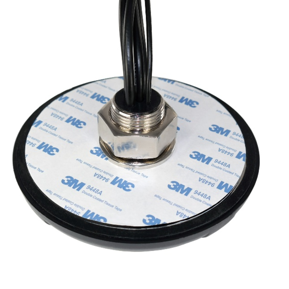
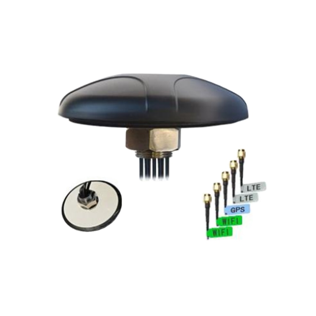
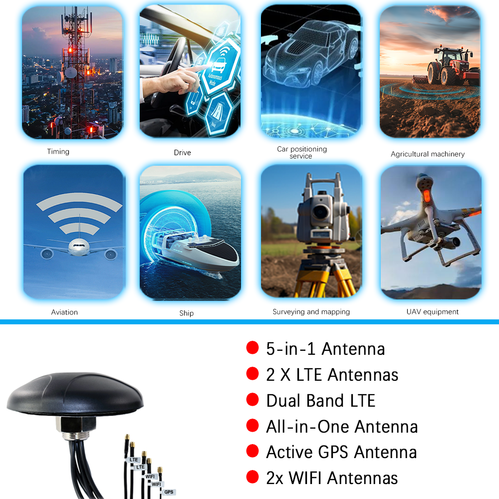
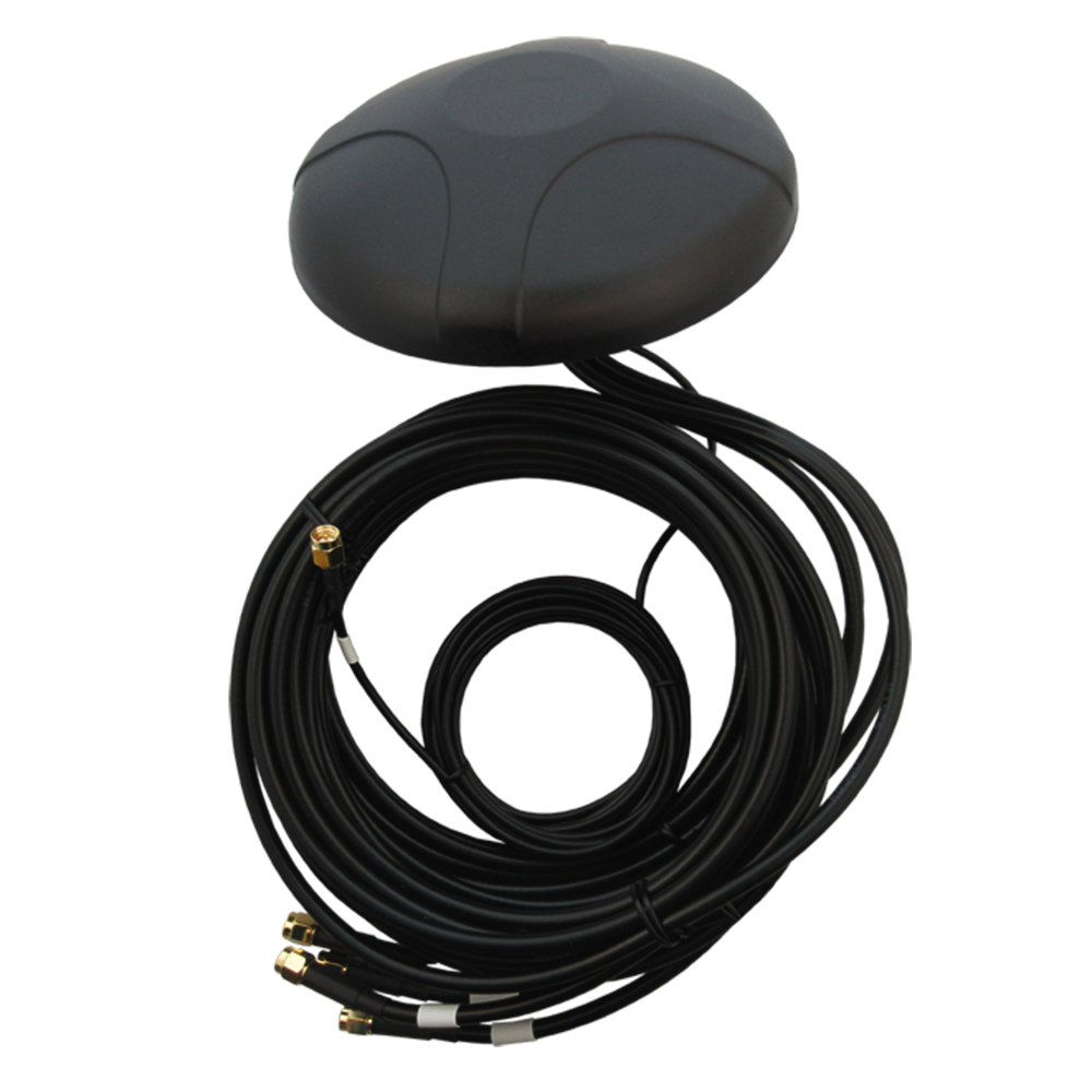
In the realm of Global Positioning System (GPS) technology, the demand for antennas that combine compact form factors with reliable performance has driven significant innovations. Among these, the low - profile mushroom GPS antenna has emerged as a standout solution, addressing critical needs in applications where space constraints, aerodynamics, and installation flexibility are paramount.

Leave a message Contact

Fill in your email address

Or you can continue to download without filling in

Overview

First, it is essential to define what distinguishes a low - profile mushroom GPS antenna. The "low - profile" attribute refers to the antennas minimal vertical height, typically measuring just a few millimeters to a few centimetersfar slimmer than traditional GPS antennas, which often require bulkier enclosures or taller structures to achieve optimal signal reception. The "mushroom" designation stems from its distinctive structural resemblance to a mushroom: a small, rounded or flat radiating element (the "cap") sits atop a short, conductive feed or support structure (the "stem"), all mounted on a ground plane (the "base"). This unique design is not merely aesthetic; it is engineered to balance size reduction with the electrical performance required for GPS signal capture, which operates primarily in the L1 band (1575.42 MHz) for civilian applications, with growing support for other bands like L2 (1227.60 MHz) and L5 (1176.45 MHz) in advanced systems.

The origins of the low - profile mushroom antenna can be traced to advancements in microstrip antenna technology, which revolutionized compact antenna design in the late 20th century. Traditional microstrip antennas, while smaller than their dipole or horn counterparts, still faced limitations in height reduction without sacrificing gain or bandwidth. The mushroom structure addressed this by leveraging a combination of a patch - like radiating element (the cap) and a shorting pin or conductive stem, which modifies the antennas electromagnetic properties to enable lower profiles. Early iterations were primarily used in military and aerospace applications, where space was at a premiumfor example, in unmanned aerial vehicles (UAVs) or satellite payloads. However, as consumer electronics, automotive systems, and IoT (Internet of Things) devices became more compact and GPS - dependent, the low - profile mushroom antenna transitioned into mainstream use.

Today, the significance of low - profile mushroom GPS antennas extends across multiple industries. In the automotive sector, for instance, modern vehicles integrate GPS for navigation, telematics, and advanced driver - assistance systems (ADAS). A low - profile design is critical here: it allows the antenna to be mounted discreetly on the roof, behind the windshield, or even within the vehicles body panels, avoiding the need for bulky external antennas that disrupt aerodynamics, increase wind noise, or are vulnerable to damage. In consumer electronics, smartphones, smartwatches, and handheld navigation devices rely on ultra - low - profile antennas to fit within their slim form factors while maintaining reliable GPS connectivity for location - based services (LBS), such as ride - hailing, fitness tracking, and mapping.

Another key driver of the antennas popularity is its compatibility with multi - band operation. As GPS evolves to include additional frequency bands (e.g., L5 for enhanced accuracy and reliability), low - profile mushroom antennas have been adapted to support these bands through modifications to the caps dimensions, the stems design, and the use of advanced substrate materials. This multi - band capability ensures that the antenna remains relevant as GPS technology advances, catering to both current and future applications.

Furthermore, the low - profile mushroom GPS antenna offers advantages in terms of installation flexibility. Its small size and flat design allow it to be mounted on curved surfaces (e.g., the fuselage of a drone or the hull of a boat) or integrated into printed circuit boards (PCBs) directly, reducing the need for complex mounting hardware. This flexibility is particularly valuable in IoT devices, where antennas must be integrated into a wide range of form factors, from tiny sensors to industrial equipment.

To understand the broader context, it is important to compare low - profile mushroom GPS antennas with other compact GPS antenna types. For example, chip antennas are extremely small but often suffer from lower gain and narrower bandwidth, making them less suitable for applications requiring reliable reception in weak signal environments (e.g., urban canyons or indoor spaces). Helical antennas, while offering good gain, are typically taller and less compatible with low - profile requirements. The low - profile mushroom antenna strikes a balance: it maintains sufficient gain and bandwidth for GPS operation while achieving the slim form factor needed for modern devices.

In summary, the low - profile mushroom GPS antenna represents a convergence of structural innovation and electrical engineering, addressing the growing demand for compact, high - performance GPS solutions. Its unique design, compatibility with multi - band operation, and installation flexibility have made it a critical component in industries ranging from automotive and consumer electronics to aerospace and IoT. As GPS technology continues to advance and devices become even more miniaturized, the role of the low - profile mushroom GPS antenna is set to expand further, driving new innovations in both antenna design and the applications it enables.


Design and Construction

The design and construction of a low - profile mushroom GPS antenna are meticulously engineered to balance three core objectives: minimal vertical height, reliable GPS signal reception (primarily in the L1 band, with optional multi - band support), and mechanical durability for integration into diverse applications. Every componentfrom the radiating cap and conductive stem to the substrate, ground plane, and feed structureplays a critical role in determining the antennas electrical performance, physical dimensions, and operational longevity. Below is a detailed breakdown of each component and the design considerations that guide their selection and integration.

2.1. Radiating Cap: The "Mushroom Cap"

The radiating cap is the primary element responsible for capturing GPS electromagnetic signals and converting them into electrical energy. Its designincluding shape, size, material, and thicknessis tailored to resonate at the target GPS frequency (e.g., 1575.42 MHz for L1) while minimizing height.

2.1.1. Shape and Size

The most common shape for the radiating cap is a circular disk, though square or rectangular caps are sometimes used for multi - band designs. The circular shape is preferred for single - band GPS applications because it offers azimuthal symmetry, ensuring consistent signal reception regardless of the antennas orientation relative to GPS satellites. The diameter of the cap is calculated based on the wavelength (λ) of the target frequency and the dielectric constant (εr) of the substrate beneath it. For a GPS L1 signal, the free - space wavelength is approximately 19 cm (λ = c/f, where c = 3×10^8 m/s and f = 1575.42 MHz). However, the presence of the substrate (which has a higher dielectric constant than air) reduces the effective wavelength, allowing the cap to be much smaller. A typical diameter for an L1 - band circular cap ranges from 10 mm to 15 mm, depending on the substrates εr (higher εr = smaller cap size).

The height of the cap is another critical parameter for achieving a low - profile design. Unlike traditional patch antennas, where the patch thickness is negligible, the mushroom cap may have a small but intentional thickness (often 0.1 mm to 0.5 mm) to enhance mechanical stability and, in some cases, adjust the antennas impedance. Thicker caps can also help broaden the antennas bandwidth, though this must be balanced against the overall height constraint (typically < 5 mm for the entire antenna).

2.1.2. Material Selection

The radiating cap is made from a highly conductive material to minimize signal loss. Copper is the most common choice due to its excellent electrical conductivity (59.6×10^6 S/m), low cost, and ease of fabrication. For applications requiring higher durability (e.g., automotive or aerospace), silver - plated copper or aluminum may be used. Silver offers slightly better conductivity than copper but is more expensive, so it is often reserved for high - performance applications where every decibel of gain matters. The material is typically deposited onto the substrate using techniques like sputtering, electroplating, or screen printing, ensuring a uniform thickness and low contact resistance.

2.2. Conductive Stem: The "Mushroom Stem"

The conductive stem connects the radiating cap to the ground plane, serving two key functions: it provides a low - impedance path for current flow, and it modifies the antennas electromagnetic mode to enable a lower profile. Unlike traditional patch antennas, which rely on a feed line along the substrate surface, the mushroom stem acts as a shorting pin or a vertical feed, depending on the design.

2.2.1. Design Variations: Shorting Pin vs. Feed Stem

There are two primary designs for the conductive stem: the shorting pin and the feed stem. In a shorting pin design, the stem is a solid conductive cylinder (or square post) that connects the center of the cap directly to the ground plane. This creates a "shorted patch" configuration, which reduces the antennas resonant frequency and allows for a smaller cap size. The shorting pin also lowers the antennas profile by eliminating the need for a bulky feed network on the substrate surface.

In a feed stem design, the stem serves as both the mechanical support and the electrical feed. In this case, the stem is not connected directly to the ground plane at its base; instead, it is connected to a feed line (e.g., a coaxial cable or microstrip line) embedded in the substrate. This design offers more flexibility in impedance matching but requires careful engineering to avoid shorting the feed to the ground plane. Some advanced designs combine both shorting pins and feed stems: multiple shorting pins surround a central feed stem, balancing profile reduction with impedance control.

2.2.2. Dimensions and Materials

The diameter of the stem is typically 0.5 mm to 2 mm, depending on the cap size and the desired current capacity. A larger diameter reduces resistance but may increase the stems impact on the antennas radiation pattern. The height of the stem is the primary contributor to the antennas overall profile; it is usually between 1 mm and 3 mm, ensuring the total antenna height (cap + stem + substrate) remains < 5 mm for most applications.

Like the radiating cap, the stem is made from a highly conductive material. Copper is again the most common choice, though brass or stainless steel may be used for applications requiring higher mechanical strength (e.g., industrial IoT devices). The stem is often fabricated as a single piece with the cap (e.g., via stamping or 3D printing) to minimize contact resistance, which can degrade signal quality.

2.3. Substrate: The "Mushroom Base Support"

The substrate is a dielectric material that separates the radiating cap from the ground plane, providing mechanical support and influencing the antennas electrical performance. Its dielectric constant (εr), loss tangent (tanδ), and thickness are critical parameters that must be carefully selected.

2.3.1. Dielectric Constant (εr)

The dielectric constant determines how the substrate interacts with electromagnetic waves, affecting the antennas resonant frequency and size. For low - profile mushroom GPS antennas, substrates with a moderate to high εr (typically 2.2 to 10) are preferred. A higher εr reduces the effective wavelength of the GPS signal, allowing the radiating cap to be smallerkey for miniaturization. Common substrate materials include:

FR4: A glass - reinforced epoxy resin with εr 4.4 (at 1 GHz) and tanδ ≈ 0.02. It is low - cost and widely used in consumer electronics but has higher loss than other materials.

Rogers 4003C: A ceramic - filled PTFE material with εr 3.55 and tanδ ≈ 0.0027. It offers lower loss than FR4, making it suitable for high - performance applications like automotive ADAS.

Alumina (AlO): A ceramic material with εr 9.8 and tanδ ≈ 0.0001. It has extremely low loss but is more expensive and brittle, used primarily in aerospace or military applications.

2.3.2. Thickness and Mechanical Properties

The substrate thickness is typically between 0.5 mm and 2 mm. A thicker substrate can increase the antennas bandwidth but may also increase its overall profile. For low - profile designs, thinner substrates are preferred, though they require careful impedance matching to avoid signal reflections. The substrate must also have sufficient mechanical strength to support the radiating cap and stem, especially in applications with vibration (e.g., vehicles or drones). Materials like Rogers 4003C or alumina offer good rigidity, while FR4 is suitable for less demanding environments.

2.4. Ground Plane

The ground plane is a conductive layer that acts as a reflector, directing the antennas radiation pattern upward toward GPS satellites (which orbit at ~20,000 km altitude) and minimizing radiation downward. It also provides a reference for the antennas impedance and reduces interference from nearby electronic components.

2.4.1. Size and Shape

The ground plane should be larger than the radiating cap to ensure optimal performance. A general rule of thumb is that the ground plane diameter (for circular designs) or side length (for square designs) should be at least 1.5 times the cap diameter. For an L1 - band antenna with a 12 mm cap, this translates to a ground plane size of ~18 mm. However, in applications where space is extremely limited (e.g., smartwatches), the ground plane may be reduced to just slightly larger than the cap, though this can result in a slight loss of gain.

The shape of the ground plane is often matched to the antennas application. For example, automotive antennas may use a rectangular ground plane to fit within roof panels, while drone antennas may use a circular ground plane for symmetry. In some cases, the ground plane is integrated into the devices PCB, using the PCBs copper layers to save space.

2.4.2. Material and Fabrication

Like the radiating cap and stem, the ground plane is made from a highly conductive materialusually copper, due to its conductivity and cost - effectiveness. It is typically fabricated as a thin layer (0.035 mm to 0.1 mm) on the bottom of the substrate, using the same techniques as the radiating cap (sputtering, electroplating, etc.). For applications requiring corrosion resistance (e.g., marine or outdoor IoT devices), the ground plane may be coated with a thin layer of nickel or gold.

2.5. Feed Structure

The feed structure delivers the electrical signal from the radiating cap to the devices GPS receiver, and vice versa (for active antennas, though most low - profile mushroom GPS antennas are passive). The design of the feed structure is critical for impedance matchingensuring that the antennas impedance (typically 50 Ω, to match most GPS receivers) is aligned with the feed lines impedance to minimize signal reflection and maximize power transfer.

2.5.1. Coaxial Feed vs. Microstrip Feed

The two most common feed structures for low - profile mushroom GPS antennas are coaxial feeds and microstrip feeds.

Coaxial Feed: A coaxial cable is used, with the inner conductor connected to the radiating cap (via the stem, in feed stem designs) and the outer conductor connected to the ground plane. Coaxial feeds offer good shielding against interference and are easy to integrate into devices with external antennas. However, the cables diameter can add to the antennas profile, so thin coaxial cables (e.g., 0.81 mm diameter) are preferred.

Microstrip Feed: A microstrip line (a thin copper trace on the substrate) connects the stem to the receiver. This feed structure is ideal for PCB - integrated antennas, as it lies flat on the substrate and does not add to the vertical profile. Microstrip feeds require careful design to match the antennas impedance; this is often achieved by tapering the trace width or adding a matching network (e.g., a stub or capacitor).

2.5.2. Impedance Matching

Impedance mismatches between the antenna and feed line can cause significant signal loss, so matching is a key step in the design process. For low - profile mushroom antennas, matching is often achieved through a combination of:

Stem Position: Adjusting the position of the feed stem relative to the caps center (off - center feeding) can tune the antennas impedance. For a circular cap, moving the stem toward the edge increases the impedance, while moving it toward the center decreases it.

Matching Networks: Lumped elements (capacitors, inductors) or distributed elements (microstrip stubs) are added to the feed line to adjust the impedance. For example, a series capacitor can compensate for inductive reactance, while a shunt inductor can compensate for capacitive reactance.

Substrate Tuning: Changing the substrates εr or thickness can also adjust the antennas impedance, though this is often a last resort due to the impact on other parameters (e.g., cap size).

2.6. Protective Enclosure (Optional)

In many applications, the low - profile mushroom GPS antenna is enclosed in a protective housing to shield it from environmental factors like moisture, dust, and physical impact. The enclosure material must be non - conductive and have a low dielectric constant to avoid interfering with GPS signals. Common materials include:

Plastics: Polycarbonate or ABS plastic, which are lightweight, durable, and have εr 2.5.

Ceramics: Alumina or zirconia, which offer higher durability (for harsh environments) but are more expensive.

The enclosures thickness is minimized (typically 0.5 mm to 1 mm) to avoid attenuating GPS signals, which are relatively weak (often < -150 dBm at the antenna).

In conclusion, the design and construction of a low - profile mushroom GPS antenna involve a delicate balance of electrical and mechanical engineering. Each componentthe radiating cap, conductive stem, substrate, ground plane, feed structure, and optional enclosureis optimized to achieve a minimal profile while maintaining the gain, bandwidth, and impedance matching required for reliable GPS reception. The choice of materials and dimensions depends on the applications specific needs, from cost - sensitive consumer electronics (using FR4 and copper) to high - performance aerospace systems (using alumina and silver - plated copper). As devices continue to miniaturize, the design of low - profile mushroom GPS antennas will evolve further, with innovations in materials and fabrication techniques further pushing the boundaries of miniaturization and performance.


Working Principles

To fully grasp the functionality of a low - profile mushroom GPS antenna, it is essential to delve into its working principles, which revolve around the interaction between electromagnetic (EM) waves from GPS satellites and the antennas structural components. Unlike active antennas that rely on amplifiers to boost signals, low - profile mushroom GPS antennas are typically passive, meaning they operate solely through the conversion of incoming EM energy into electrical signals without external power. This section breaks down the key stages of the antennas operation: EM wave reception by the radiating cap, energy conversion and current generation, signal propagation through the feed structure, and the role of the ground plane in optimizing radiation patternsall while explaining how the mushrooms unique design enables efficient performance in a compact form.

3.1. Electromagnetic Wave Reception by the Radiating Cap

GPS satellites orbit the Earth in medium Earth orbit (MEO), approximately 20,200 km above the surface, and continuously transmit EM signals in the L - band frequency range (e.g., 1575.42 MHz for L1). These signals travel through the atmosphere (ionosphere and troposphere) and reach the Earths surface, where they encounter the low - profile mushroom GPS antenna. The radiating cap, as the antennas primary receiving element, is engineered to interact with these EM waves through a phenomenon known as resonance.

Resonance occurs when the natural frequency of the radiating cap matches the frequency of the incoming GPS signal. For the L1 band, this means the caps dimensions (diameter, thickness) and the substrates dielectric constant (εr) are precisely tuned so that the cap oscillates in sync with the EM waves electric field. When the EM wave strikes the cap, its alternating electric field exerts a force on the free electrons in the caps conductive material (e.g., copper). This force causes the electrons to oscillate back and forth at the same frequency as the EM wave1575.42 MHz for L1 signals.

The circular shape of the cap plays a critical role in this process by providing azimuthal symmetry. GPS satellites are distributed evenly across six orbital planes, so signals can arrive from any horizontal direction (azimuth angle). A circular cap ensures that the antennas ability to receive signals is consistent regardless of the satellites position in the sky, eliminating directional "dead zones" that might occur with non - symmetric designs (e.g., rectangular patches in some microstrip antennas). This symmetry is especially important in mobile applications like smartphones or drones, where the antennas orientation relative to satellites is constantly changing.

The caps thickness also influences reception efficiency. While traditional patch antennas have negligible thickness, the mushroom caps intentional thickness (0.1 mm0.5 mm) increases the volume of conductive material available for electron oscillation. This larger electron pool enhances the caps ability to capture EM energy, improving the antennas power capture efficiencya key metric for GPS applications, where signals are extremely weak (typically -130 dBm to -150 dBm at the antenna, equivalent to a few picowatts of power).

3.2. Energy Conversion and Current Generation

The oscillation of electrons in the radiating cap is not just a physical phenomenonit directly translates to the generation of an electrical current. This process, known as energy conversion, is the core of the antennas functionality: it transforms the EM waves energy into usable electrical energy that can be processed by the GPS receiver.

To understand this conversion, it helps to visualize the EM waves structure. A GPS signal consists of two perpendicular fields: an electric field (E - field) and a magnetic field (H - field), both oscillating at the signals frequency and propagating in the same direction (toward the antenna). The E - field is responsible for driving electron motion in the cap. As the E - field alternates (positive to negative), it pulls electrons in one direction and then the opposite, creating an alternating current (AC) in the cap.

The conductive stem plays a pivotal role in channeling this current. In a feed stem design, the stem acts as a vertical conduit, transferring the AC current from the cap to the feed structure (e.g., microstrip line or coaxial cable). In a shorting pin design, the stem connects the cap to the ground plane, creating a closed circuit that enhances current flow. In advanced designs with multiple shorting pins, the pins distribute the current evenly across the cap, reducing signal loss and improving impedance matching.

The substrate also influences current generation by modifying the EM waves propagation speed. As mentioned earlier, the substrates dielectric constant (εr) is higher than that of air, which slows down the EM wave as it passes through the substrate. This slowing effect reduces the waves wavelength, allowing the cap to be smaller (as calculated by λeff = λ0 / √εr, where λeff is the effective wavelength and λ0 is the free - space wavelength). A smaller cap means the electron oscillation is more concentrated, increasing the current density (amps per unit area) in the cap and stem. Higher current density translates to a stronger electrical signal, which is critical for overcoming noise in the GPS receiver.

3.3. Signal Propagation and Impedance Matching

Once the AC current is generated in the cap and stem, it must be propagated to the GPS receiver with minimal loss. This is where the feed structure and impedance matching come into play. Impedance (Z), measured in ohms (Ω), is a measure of how much a component opposes the flow of AC current. For maximum power transfer from the antenna to the receiver, the antennas impedance must match the receivers input impedance (typically 50 Ω for most GPS modules). A mismatch would cause a portion of the signal to be reflected back to the antenna, rather than transmitted to the receiverresulting in signal loss and degraded performance.

3.3.1. Role of the Feed Structure

The feed structure (coaxial or microstrip) acts as a bridge between the stem and the receiver, guiding the AC current while maintaining impedance consistency.

Coaxial Feed: In this design, the coaxial cables inner conductor is connected to the feed stem, and the outer conductor is connected to the ground plane. The coaxial cables impedance is fixed (e.g., 50 Ω), so the antennas impedance (determined by the cap, stem, and substrate) must be tuned to match this value. The cables shielding (outer conductor) also prevents external interference from coupling into the signal, which is crucial in noisy environments (e.g., near automotive electronics or smartphone components).

Microstrip Feed: A microstrip linea thin copper trace on the substrateconnects the stem to the receiver. The traces width and length are designed to achieve 50 Ω impedance. For example, a microstrip line on an FR4 substrate (εr = 4.4) with a thickness of 1.6 mm would require a trace width of approximately 3 mm to achieve 50 Ω impedance. The microstrip feeds flat design keeps the antennas profile low, making it ideal for PCB - integrated applications like smartwatches.

3.3.2. Tuning Techniques for Impedance Matching

As discussed in the Design and Construction section, several techniques are used to match the antennas impedance to the feed line:

Off - Center Feeding: For a circular cap, moving the feed stem away from the center increases the antennas impedance. This is because the caps current distribution changeselectrons have a longer path to travel from the stem to the caps edge, increasing resistance. By adjusting the stems position (e.g., 2 mm from the center for a 12 mm cap), engineers can tune the impedance to 50 Ω.

Matching Networks: Lumped elements (capacitors, inductors) or distributed elements (microstrip stubs) are added to the feed line to correct impedance mismatches. For example, if the antennas impedance is 30 Ω (capacitive), a series inductor can be added to increase the impedance to 50 Ω. Similarly, a microstrip stub (a short, open - circuited section of the feed line) can be used to cancel out reactive components (capacitance or inductance) in the antennas impedance.

Substrate Adjustments: Changing the substrates εr or thickness can shift the antennas impedance. For instance, increasing the substrates εr reduces the caps size, which increases the current density and lowers the impedance. This technique is often used as a final tuning step after adjusting the stem position and adding matching networks.

3.4. Ground Planes Role in Radiation Pattern Optimization

The ground plane is not just a mechanical supportit is a critical component that shapes the antennas radiation pattern, which describes how the antenna radiates (or receives) EM energy in space. For GPS antennas, the ideal radiation pattern is hemisphericalmeaning the antenna receives signals primarily from the upper half - space (toward the sky), where GPS satellites are located, and minimizes reception from the lower half - space (toward the ground), where interference from buildings, terrain, or electronic devices is common.

The ground plane achieves this by acting as a reflector for EM waves. When the radiating cap generates an EM field, a portion of this field travels downward toward the ground plane. The ground planes conductive material reflects this downward - traveling field upward, combining it with the upward - traveling field from the cap. This constructive interference enhances the antennas gain in the upper half - space.

The ground planes size directly impacts the radiation patterns directionality. A larger ground plane (e.g., 1.5 times the cap diameter) creates a more focused hemispherical pattern, with higher gain (typically 2 dBi to 4 dBi for L1 - band mushroom antennas). Gain is a measure of the antennas ability to concentrate energy in a specific directionhigher gain means the antenna can receive weaker signals from distant satellites. However, if the ground plane is too small (e.g., only slightly larger than the cap), the reflected field is weaker, and the radiation pattern becomes more omnidirectional (receiving signals from all directions), which increases interference and reduces gain.

The ground plane also reduces surface wave losses. Surface waves are EM waves that travel along the surface of the substrate, rather than radiating into space. These waves do not contribute to signal reception and can cause energy loss. The ground plane absorbs surface waves, converting their energy into heat (though this loss is minimal with low - loss substrates like Rogers 4003C). By eliminating surface waves, the ground plane ensures that most of the antennas energy is used for receiving GPS signals, improving efficiency.

3.5. Multi - Band Operation Principles (for Advanced Designs)

While many low - profile mushroom GPS antennas are designed for single - band (L1) operation, advanced models support multi - band reception (e.g., L1 + L5) to enhance accuracy and reliability. Multi - band operation relies on modifying the antennas structure to resonate at multiple frequencies simultaneously.

One common approach is to use a stacked cap design: two or more radiating caps are layered vertically (separated by thin dielectric spacers) on a single stem. Each cap is tuned to a different GPS bandfor example, a larger cap (15 mm diameter) for L1 (1575.42 MHz) and a smaller cap (12 mm diameter) for L5 (1176.45 MHz). The dielectric spacer between the caps (e.g., a 0.1 mm layer of Teflon, εr = 2.1) prevents mutual coupling between the caps, ensuring each resonates independently.

Another technique is to use a shaped cap (e.g., a circular cap with a notched edge or a square cap with rounded corners). The shape introduces multiple resonant modes, allowing the cap to resonate at two or more frequencies. For example, a square cap with a side length of 14 mm can resonate at L1 (1575.42 MHz) in its fundamental mode and at L5 (1176.45 MHz) in a higher - order mode. The stems position is then adjusted to optimize impedance matching for both bands.

In multi - band designs, the feed structure and ground plane are also optimized. The feed line may include a multi - band matching network (e.g., two separate stubs for L1 and L5) to ensure impedance matching at each frequency. The ground plane is sized to support the largest cap, ensuring consistent radiation patterns across all bands.

3.6. Summary of Working Principles

In summary, the low - profile mushroom GPS antenna operates through a sequence of interconnected processes:

Reception: The radiating cap, tuned to GPS frequencies via resonance, captures incoming EM waves from satellites.

Energy Conversion: The EM waves electric field drives electron oscillation in the cap, generating an AC current.

Current Propagation: The conductive stem channels the AC current to the feed structure (coaxial or microstrip).

Impedance Matching: The feed structure and matching networks ensure maximum power transfer to the receiver by aligning the antennas impedance with the receivers input impedance.

Radiation Pattern Optimization: The ground plane reflects downward - traveling EM fields upward, creating a hemispherical radiation pattern ideal for GPS reception.

For multi - band designs, additional modifications (stacked caps, shaped caps) enable resonance at multiple frequencies, enhancing performance in challenging environments. This combination of processesenabled by the mushrooms unique low - profile structureallows the antenna to deliver reliable GPS reception in a compact form factor, making it suitable for the most space - constrained applications.


Advantages and Challenges

The low - profile mushroom GPS antennas design and working principles give rise to a set of distinct advantages that have made it a preferred choice in diverse industries, from consumer electronics to aerospace. However, it also faces unique challenges related to its compact size, environmental resilience, and performance in demanding conditions. This section explores these advantages and challenges in detail, providing context for why the antenna is well - suited to certain applications while requiring careful engineering to overcome limitations.

4.1. Key Advantages

4.1.1. Ultra - Low Profile for Space - Constrained Applications

The most defining advantage of the low - profile mushroom GPS antenna is its minimal vertical height, typically < 5 mm for the entire assembly (cap + stem + substrate + ground plane). This makes it ideal for devices where space is at a premiumapplications where traditional GPS antennas (e.g., helical or patch antennas with heights of 10 mm20 mm) would be too bulky.

In consumer electronics, for example, modern smartphones have thicknesses of just 7 mm10 mm. A low - profile mushroom antenna can be integrated into the phones PCB, either behind the display or near the top edge, without adding to the devices overall thickness. Similarly, smartwatcheswith case heights of 10 mm or lessrely on ultra - low - profile antennas to fit within their compact enclosures while maintaining GPS functionality for fitness tracking (e.g., distance monitoring during runs) or location sharing.

In the automotive industry, the low profile enables discreet installation. Unlike bulky external "shark fin" antennas (which can be 30 mm50 mm tall), mushroom antennas can be mounted under the roof liner, behind the windshield, or even within the rearview mirror housing. This not only improves the vehicles aerodynamics (reducing wind resistance and fuel consumption) but also eliminates the risk of antenna damage from vandalism or low - hanging obstacles (e.g., garage ceilings). For electric vehicles (EVs), where aerodynamics directly impact range, this advantage is particularly valuable.

In aerospace and UAVs, the low profile is critical for maintaining the vehicles structural integrity and aerodynamic performance. A UAVs fuselage or wing may have limited space for antennas, and a tall antenna could disrupt airflow or increase drag. The mushroom antennas slim design allows it to be embedded in the UAVs body, ensuring reliable GPS reception for navigation and waypoint tracking without compromising flight efficiency.

4.1.2. Balanced Gain and Bandwidth for Reliable GPS Reception

Despite its small size, the low - profile mushroom GPS antenna delivers sufficient gain and bandwidth for reliable GPS operationaddressing a key limitation of other compact antenna types (e.g., chip antennas).

Gain for L1 - band mushroom antennas typically ranges from 2 dBi to 4 dBi. While this is lower than the gain of larger antennas (e.g., 5 dBi7 dBi for helical antennas), it is more than adequate for most GPS applications. GPS signals are designed to be received by low - gain antennas, as satellites transmit with sufficient power to overcome atmospheric attenuation and antenna losses. The mushroom antennas gain is concentrated in the upper half - space (due to the ground plane), ensuring that most of the received energy comes from GPS satellites, not from ground - based interference.

Bandwidththe range of frequencies over which the antenna maintains acceptable performance (e.g., impedance < 2:1 VSWR, or Voltage Standing Wave Ratio)is another key strength. For L1 - band operation, the mushroom antenna typically offers a bandwidth of 10 MHz20 MHz, which covers the entire L1 band (1575.42 MHz ± 1.023 MHz) and provides margin for frequency drift due to temperature changes or manufacturing tolerances. For multi - band designs (e.g., L1 + L5), bandwidth can be extended to cover both bands, with each band having its own 10 MHz20 MHz bandwidth. This ensures that the antenna can receive signals from GPS satellites even if the signals frequency varies slightly (e.g., due to Doppler shift from satellite motion).

This balance of gain and bandwidth makes the mushroom antenna reliable in challenging signal environments, such as urban canyons (where buildings reflect GPS signals) or suburban areas (where tree foliage attenuates signals). In these environments, the antennas ability to capture weak signals (thanks to its gain) and maintain performance across a range of frequencies (thanks to its bandwidth) ensures that the GPS receiver can maintain a lock on satellites.

4.1.3. Azimuthal Symmetry for Omnidirectional Reception

As discussed in the Working Principles section, the circular radiating cap provides azimuthal symmetrymeaning the antennas reception is consistent regardless of the satellites azimuth angle (horizontal direction).This is a critical advantage in mobile applications where the antennas orientation is not fixed. For example, when a user carries a smartphone in their pocket, the phone can rotate freelychanging the antennas azimuth relative to GPS satellites. A mushroom antennas azimuthal symmetry ensures that signal reception remains consistent, regardless of whether the phone is facing north, south, east, or west. Without this symmetry, the antenna might experience "dropouts" in reception when rotated, leading to inaccurate location data or lost GPS locks.

In drones, which often maneuver rapidly and change orientation during flight, azimuthal symmetry is equally important. A drones GPS antenna must receive signals from satellites in all horizontal directions to maintain stable navigation. The mushroom antennas circular cap ensures that even as the drone rolls, pitches, or yaws, it can still capture signals from satellites in any azimuth, preventing navigation errors that could lead to crashes or mission failure.

For automotive applications, azimuthal symmetry is beneficial when the vehicle is moving in different directions (e.g., turning corners or reversing). The antenna can receive signals from satellites ahead, behind, or to the sides of the vehicle, ensuring continuous GPS coverage for navigation and telematics (e.g., real - time tracking for fleet management).

4.1.4. Cost - Effectiveness and Ease of Mass Production

Low - profile mushroom GPS antennas are highly cost - effective to manufacture, making them suitable for high - volume applications like consumer electronics and automotive production. This cost advantage stems from several factors related to their design and fabrication:

First, the antennas components are simple and use low - cost materials. The radiating cap and ground plane are typically made from copper, which is abundant and affordable. The substrate can be made from FR4a common, low - cost PCB materialfor consumer applications, or higher - performance materials like Rogers 4003C for more demanding use cases (though these are still less expensive than materials used in specialized antennas like phased arrays).

Second, the fabrication process is compatible with standard PCB manufacturing techniques. The radiating cap and ground plane can be deposited onto the substrate using sputtering, electroplating, or screen printingprocesses that are already widely used in PCB production. This eliminates the need for specialized manufacturing equipment, reducing capital costs for manufacturers. For example, a smartphone manufacturer can integrate the mushroom antenna into the devices main PCB during the standard PCB assembly process, rather than requiring a separate production line for the antenna.

Third, the antennas design is highly reproducible. The dimensions of the cap, stem, and substrate can be precisely controlled using computer - aided design (CAD) software, and manufacturing tolerances are easy to maintain (e.g., ±0.1 mm for cap diameter). This ensures that each antenna performs consistently, reducing the need for expensive testing and quality control checks. In high - volume production (e.g., millions of smartphones per year), this reproducibility is critical for minimizing defects and keeping costs low.

Compared to other compact antenna types, the cost advantage is significant. For example, chip antennas require specialized ceramic materials and precision machining, making them more expensive than mushroom antennas. Helical antennas, which have a more complex 3D structure, require manual assembly in some cases, increasing labor costs. The mushroom antennas combination of low - cost materials, standard manufacturing processes, and high reproducibility makes it the most cost - effective choice for many high - volume applications.

4.1.5. Compatibility with Integration into Multi - Function Antennas

In modern devices, there is a growing trend toward multi - function antennasantennas that support multiple wireless technologies (e.g., GPS, Wi - Fi, Bluetooth, 5G) in a single package. Low - profile mushroom GPS antennas are highly compatible with this integration, thanks to their compact size and low interference with other antenna elements.

The mushroom antennas small footprint means it can be placed alongside other antenna elements (e.g., a Wi - Fi patch antenna or a 5G dipole antenna) on a single PCB without causing significant interference. The ground plane of the mushroom antenna also acts as a shield, preventing the GPS signal from coupling into other antenna elements and vice versa. For example, in a smartphone, the mushroom GPS antenna can be placed near the Wi - Fi/Bluetooth antenna on the top edge of the PCB. The GPS antennas ground plane isolates its signal from the Wi - Fi/Bluetooth signal, ensuring that both technologies operate independently without degradation.

This compatibility is critical for devices with limited space, where integrating separate antennas for each technology would be impractical. For example, a smartwatch may need to support GPS (for location tracking), Bluetooth (for connecting to a smartphone), and Wi - Fi (for data syncing). A multi - function antenna that includes a mushroom GPS element can combine all three technologies into a single, compact package, saving space and reducing the devices overall size.

4.2. Key Challenges

4.2.1. Signal Attenuation in Extreme Environments

While low - profile mushroom GPS antennas perform well in typical environments, they are susceptible to signal attenuation in extreme conditionssuch as dense urban canyons, indoor spaces, or areas with heavy foliage. This attenuation is a result of the antennas relatively low gain (2 dBi4 dBi) compared to larger antennas like helical or external patch antennas.

In dense urban canyons, tall buildings block and reflect GPS signals. The mushroom antennas low gain means it has less ability to capture weak reflected signals, leading to reduced signal strength and potential GPS lock loss. For example, a smartphone user walking in a downtown area with skyscrapers may experience intermittent GPS reception, as the mushroom antenna struggles to capture signals that have been attenuated by building walls.

Indoor environments are even more challenging. GPS signals are attenuated by building materials like concrete, steel, and glasslosing up to 20 dB or more of their strength by the time they reach the interior of a building. The mushroom antennas low gain is often insufficient to capture these weak indoor signals, making it unsuitable for indoor GPS applications (e.g., indoor navigation in malls or warehouses). In such cases, supplementary technologies like indoor positioning systems (IPS) using Wi - Fi or Bluetooth beacons are required, adding complexity and cost to the device.

Heavy foliage (e.g., dense forests or jungles) also attenuates GPS signals. Tree leaves and branches absorb and scatter the signals, reducing their strength. The mushroom antennas low gain makes it difficult to receive these scattered signals, limiting its use in outdoor applications like forestry or jungle exploration. In these cases, larger antennas with higher gain (e.g., helical antennas) are often preferred, despite their bulkier size.

4.2.2. Sensitivity to Environmental Factors

Low - profile mushroom GPS antennas are sensitive to environmental factors like temperature, moisture, and vibrationfactors that can degrade their performance over time.

Temperature changes can cause the antennas components to expand or contract, altering the dimensions of the radiating cap, stem, and substrate. This dimensional change shifts the antennas resonant frequency, leading to impedance mismatch and reduced signal reception. For example, in automotive applications, the antenna may be exposed to temperatures ranging from -40°C (in cold climates) to 85°C (in hot climates). At high temperatures, the substrate (e.g., FR4) may expand, increasing the caps diameter and lowering the resonant frequency. If the resonant frequency shifts too far from the GPS L1 band (1575.42 MHz), the antenna will no longer efficiently capture signals, leading to GPS lock loss.

Moisture is another significant threat. If water or humidity penetrates the antennas enclosure (if present), it can short - circuit the conductive components (cap, stem, ground plane) or alter the substrates dielectric constant. For example, in outdoor IoT devices like weather sensors, the mushroom antenna may be exposed to rain or high humidity. Water absorption by the substrate increases its dielectric constant, which shifts the antennas resonant frequency and reduces its gain. Over time, this can lead to permanent damage to the antenna if moisture is not properly sealed out.

Vibration, common in automotive and aerospace applications, can also degrade the antennas performance. Continuous vibration can loosen the connection between the stem and the feed structure, leading to increased contact resistance and signal loss. In extreme cases, vibration can cause the stem to break or the cap to detach from the substrate, rendering the antenna inoperable. For example, in a commercial truck that travels on rough roads, the mushroom antenna mounted on the dashboard may experience constant vibration, leading to premature failure if not properly secured.

4.2.3. Limited Gain for Long - Range or Weak - Signal Applications

While the mushroom antennas gain (2 dBi4 dBi) is sufficient for most standard GPS applications, it is limited for use cases requiring long - range reception or operation in extremely weak signal environments.

One such application is precision agriculture, where GPS - enabled equipment (e.g., autonomous tractors) requires centimeter - level accuracy. This level of accuracy often relies on differential GPS (DGPS) or real - time kinematic (RTK) GPS, which use signals from base stations to correct GPS errors. The weak signals from these base stations (which may be tens of kilometers away) require an antenna with higher gain to capture reliably. The mushroom antennas low gain may not be sufficient to receive these weak DGPS/RTK signals, leading to reduced accuracy or loss of correction data.

Another application is aerospace, where satellites or high - altitude UAVs (HAPs) require GPS reception at extreme distances. Satellites in low Earth orbit (LEO) may be thousands of kilometers from GPS satellites, and the GPS signals they receive are extremely weak. The mushroom antennas low gain is insufficient to capture these weak signals, requiring larger, higher - gain antennas like phased arrays or parabolic reflectors.

Even in some terrestrial applications, like marine navigation, the mushroom antennas limited gain can be a problem. In open ocean, GPS signals are relatively strong, but in coastal areas with fog, rain, or heavy cloud cover, signals can be attenuated. A higher - gain antenna would be better able to capture these weak signals, ensuring reliable navigation. The mushroom antennas low gain may struggle in these conditions, leading to navigation errors.

4.2.4. Design Complexity for Multi - Band and High - Performance Versions

While single - band (L1) low - profile mushroom GPS antennas are relatively simple to design, multi - band and high - performance versions (e.g., L1 + L5, high - gain designs) require significantly more complex engineering, increasing development time and cost.

Multi - band designs, which support multiple GPS bands (e.g., L1 and L5) to enhance accuracy, require careful optimization of the radiating cap, stem, and feed structure. For example, a stacked cap design requires precise spacing between the caps to prevent mutual coupling, and each cap must be tuned to its respective frequency. The feed structure must include a multi - band matching network to ensure impedance matching at each frequency, which adds complexity to the design. In some cases, the use of higher - performance materials (e.g., Rogers 4003C instead of FR4) is required to maintain bandwidth and gain across multiple bands, increasing material costs.

High - gain designs, which aim to increase the antennas gain beyond the standard 2 dBi4 dBi range, also face design challenges. One approach to increasing gain is to use an array of mushroom antennas (a "mushroom array"), where multiple mushroom elements are arranged in a grid. However, this increases the antennas footprint, which contradicts the low - profile advantage. Another approach is to use a larger ground plane to focus the radiation pattern, but this also increases the antennas size. Balancing gain, size, and profile is a significant engineering challenge, and high - gain mushroom antennas often require extensive simulation and testing (using tools like ANSYS HFSS or CST Microwave Studio) to optimize performance, increasing development time and cost.

Compared to single - band designs, multi - band and high - performance mushroom antennas are more expensive to develop and manufacture, making them less suitable for cost - sensitive applications. For example, a consumer smartphone may use a single - band mushroom antenna to keep costs low, while a high - end automotive ADAS system may require a multi - band, high - gain versionadding to the systems overall cost.


Applications and Future Trends

5.1. Current Applications

The low - profile mushroom GPS antennas unique combination of small size, reliable performance, and cost - effectiveness has made it a staple in a wide range of industries. Below are its key current applications, highlighting how it addresses specific needs in each sector.

5.1.1. Consumer Electronics

Consumer electronics is the largest market for low - profile mushroom GPS antennas, driven by the demand for compact, multi - function devices like smartphones, smartwatches, and handheld navigation devices.

Smartphones: Modern smartphones rely on GPS for location - based services (LBS) such as mapping (Google Maps, Apple Maps), ride - hailing (Uber, Lyft), food delivery, and fitness tracking. The low - profile mushroom antenna is integrated into the phones PCB, typically near the top edge or behind the display, to avoid adding to the devices thickness. For example, Apples iPhone uses a low - profile GPS antenna (likely a mushroom or similar microstrip design) to support GPS, GLONASS, Galileo, and BeiDou, enabling accurate location tracking for apps like Apple Fitness+ (which monitors outdoor runs) and Find My iPhone. The antennas azimuthal symmetry ensures consistent reception even when the phone is in the users pocket or hand, and its cost - effectiveness makes it suitable for high - volume production.

Smartwatches and Wearables: Smartwatches (e.g., Apple Watch, Samsung Galaxy Watch) and other wearables (e.g., fitness trackers like Fitbit Charge) use GPS to track outdoor activities such as running, cycling, and hiking. The ultra - low profile of the mushroom antenna is critical here, as wearables must be lightweight and comfortable to wear. The antenna is often integrated into the watchs case or strap, with a small PCB serving as the ground plane. For example, the Apple Watch Ultra uses a low - profile GPS antenna to support precision location tracking for outdoor adventures, including backcountry hiking and ocean kayaking. The antennas compact size allows it to fit within the watchs 14.4 mm thick case, while its gain (3 dBi) is sufficient to receive GPS signals even in remote areas.

Handheld Navigation Devices: Handheld GPS devices used for hiking, camping, and geocaching also use low - profile mushroom antennas. These devices require reliable GPS reception in outdoor environments but must be compact and lightweight for portability. The mushroom antennas low profile allows the device to be slim and easy to carry, while its bandwidth ensures it can receive signals from multiple GNSS systems (GPS, GLONASS, Galileo) for improved accuracy. For example, Garmins eTrex series of handheld GPS devices uses a low - profile antenna to support multi - GNSS reception, enabling users to navigate in remote areas with limited satellite visibility.

5.1.2. Automotive Industry

The automotive industry relies on low - profile mushroom GPS antennas for navigation, telematics, and advanced driver - assistance systems (ADAS), where discreet installation and aerodynamic performance are key.

In - Vehicle Navigation: Most modern vehicles come equipped with built - in navigation systems that use GPS to provide turn - by - turn directions. The low - profile mushroom antenna is mounted discreetly inside the vehicletypically under the roof liner, behind the windshield, or within the rearview mirrorto avoid disrupting the vehicles exterior design. For example, Tesla vehicles use a low - profile GPS antenna integrated into the rearview mirror housing to support the cars navigation system and Autopilot features. The antennas low profile ensures it does not affect the vehicles aerodynamics, which is critical for maximizing electric vehicle (EV) range.

Telematics and Fleet Management: Fleet operators use GPS - enabled telematics systems to track vehicle location, monitor driver behavior (e.g., speed, idling time), and optimize routes. The low - profile mushroom antenna is ideal for this application because it can be installed quickly and discreetly on any vehicle (cars, trucks, vans) without requiring external mounting. For example, Verizon Connects telematics devices use a low - profile GPS antenna to provide real - time tracking for fleet managers, enabling them to reduce fuel costs and improve delivery efficiency. The antennas compatibility with multi - GNSS systems ensures reliable tracking even in urban areas with tall buildings.

Advanced Driver - Assistance Systems (ADAS): ADAS features like adaptive cruise control, lane - keeping assist, and automatic emergency braking rely on precise GPS positioning to function safely. The low - profile mushroom antenna provides the accurate location data needed for these systems, with multi - band support (e.g., L1 + L5) enhancing accuracy and reliability. For example, Mercedes - Benzs Drive Pilot system (a Level 3 autonomous driving system) uses a multi - band low - profile GPS antenna to provide centimeter - level positioning, enabling the car to navigate highways autonomously. The antennas compact size allows it to be integrated into the vehicles roof, while its high bandwidth ensures it can receive signals from multiple GPS bands to correct for ionospheric delays.

5.1.3. Aerospace and Unmanned Aerial Vehicles (UAVs)

In aerospace and UAVs, the low - profile mushroom GPS antennas small size and lightweight design make it suitable for applications where space and weight are critical constraints.

UAVs for Commercial and Consumer Use: Consumer drones (e.g., DJI Mavic series) and commercial UAVs (used for aerial photography, agriculture, and infrastructure inspection) rely on GPS for navigation, waypoint tracking, and return - to - home (RTH) functionality. The low - profile mushroom antenna is integrated into the drones fuselage or wing, where its small size and lightweight design do not affect flight performance. For example, the DJI Mavic 3 uses a low - profile GPS antenna to support precise hovering and waypoint navigation, enabling the drone to capture stable aerial footage. The antennas azimuthal symmetry ensures it can receive signals from satellites in all directions, even as the drone maneuvers.

Aerospace Satellites and High - Altitude Platforms (HAPs): Small satellites (e.g., CubeSats) and HAPs (e.g., high - altitude balloons) use low - profile mushroom GPS antennas for orbit determination and navigation. These platforms have strict size and weight constraints, and the mushroom antennas low profile and lightweight nature (typically weighing < 1 gram) make it an ideal choice. For example, CubeSatssmall satellites with dimensions as small as 10 cm × 10 cm × 10 cmrely on compact GPS antennas to determine their orbit and maintain attitude. A low - profile mushroom antenna can be integrated into the CubeSats exterior panel, where it occupies minimal space and adds negligible weight. The antennas ability to receive signals from multiple GNSS systems (GPS, GLONASS) ensures accurate orbit determination, even in low Earth orbit (LEO) where satellite visibility can change rapidly.

HAPs, such as high - altitude balloons used for atmospheric research or communication relay, also benefit from the mushroom antennas design. These platforms operate at altitudes of 20 km30 km, where weight and aerodynamics are critical. The low - profile antenna can be mounted on the balloons payload module, receiving GPS signals to track the platforms position and trajectory. This data is essential for guiding the balloon to specific locations (e.g., a research area) and retrieving the payload safely.

5.1.4. IoT and Industrial Automation

The Internet of Things (IoT) and industrial automation sectors are increasingly adopting low - profile mushroom GPS antennas for asset tracking, remote monitoring, and precision controlapplications where compact size and low power consumption are key.

    Asset Tracking: Companies use GPS - enabled IoT devices to track the location of valuable assets, such as shipping containers, construction equipment, and medical supplies. The low - profile mushroom antenna is integrated into small, battery - powered tracking devices, allowing them to be attached discreetly to assets. For example, a shipping container tracking device equipped with a mushroom antenna can be mounted inside the container, where it receives GPS signals to provide real - time location data. This helps logistics companies optimize shipping routes, prevent theft, and reduce delivery delays. The antennas low power consumption (a key feature of passive designs) extends the tracking devices battery life, which is critical for assets that are in transit for weeks or months.

    Remote Monitoring: In industrial settings, remote monitoring systems use GPS to track the location of sensors and equipment in remote areas (e.g., oil fields, wind farms). For example, a sensor deployed in a wind farm to monitor turbine performance may use a low - profile mushroom antenna to transmit its location along with sensor data (e.g., wind speed, turbine temperature). This allows operators to quickly locate and maintain faulty sensors, minimizing downtime. The antennas compact size enables it to be integrated into the sensors small enclosure, while its reliability ensures consistent GPS reception in harsh outdoor environments.

    Precision Control: Industrial automation systems, such as automated guided vehicles (AGVs) in warehouses, use GPS for precision navigation. AGVs rely on accurate location data to move safely through warehouse aisles, avoiding obstacles and delivering goods to the correct location. The low - profile mushroom antenna is mounted on the AGVs body, where its azimuthal symmetry ensures consistent GPS reception even as the vehicle turns or reverses. For example, an AGV in an e - commerce warehouse may use a mushroom antenna to receive GPS signals, enabling it to navigate between storage racks with centimeter - level accuracy. This improves warehouse efficiency and reduces the risk of collisions.

5.2. Future Trends

As technology advances and application requirements evolve, several key trends are expected to shape the future of low - profile mushroom GPS antennas. These trends focus on addressing current challenges (e.g., limited gain, environmental sensitivity) and expanding the antennas capabilities to support emerging technologies.

5.2.1. Integration with Advanced Materials for Enhanced Performance

One of the most promising trends is the use of advanced materials to improve the performance and durability of low - profile mushroom GPS antennas. Researchers and manufacturers are exploring new materials to address key limitations, such as signal attenuation, environmental sensitivity, and limited gain.

    Low - Loss, High - Dielectric Constant Materials: New ceramic - polymer composites are being developed to replace traditional substrates like FR4. These composites offer a higher dielectric constant (εr > 10) and lower loss tangent (tanδ < 0.001), allowing for even smaller antenna sizes while maintaining high efficiency. For example, a composite material with εr = 15 could reduce the diameter of an L1 - band radiating cap by 30% compared to FR4, making the antenna suitable for ultra - compact devices like smart glasses or tiny IoT sensors.

    Flexible and Stretchable Materials: The demand for flexible electronics (e.g., foldable smartphones, wearable health monitors) is driving the development of flexible low - profile mushroom GPS antennas. These antennas use flexible substrates (e.g., polyimide, graphene - based films) and conductive materials (e.g., silver nanowires, conductive polymers) that can bend or stretch without degrading performance. For example, a flexible mushroom antenna integrated into a foldable smartphone could maintain reliable GPS reception even when the phone is folded or unfolded. This expands the antennas use in wearable and flexible devices, where traditional rigid antennas would fail.

    Environmentally Resistant Coatings: To address environmental sensitivity, new protective coatings are being developed to shield the antenna from moisture, temperature extremes, and corrosion. For example, a hydrophobic coating (e.g., a fluoropolymer) applied to the radiating cap and substrate can prevent water absorption, reducing the risk of resonant frequency shifts and short - circuits. Similarly, a thermal barrier coating can insulate the antenna from extreme temperatures, ensuring stable performance in automotive and aerospace applications. These coatings add minimal thickness to the antenna (typically < 0.1 mm), preserving its low - profile advantage.

5.2.2. Multi - Band and Multi - GNSS Support for Improved Accuracy

As GPS technology evolves to include new frequency bands (e.g., L5, L6) and other GNSS systems (e.g., BeiDou - 3, Galileo Second Generation) expand their coverage, future low - profile mushroom GPS antennas will increasingly support multi - band and multi - GNSS operation. This trend aims to enhance positioning accuracy, reliability, and resilience in challenging environments.

    Multi - Band Operation: The L5 band (1176.45 MHz) is gaining popularity for its higher accuracy and resistance to interference compared to the traditional L1 band. Future mushroom antennas will be designed to support both L1 and L5 bands (and potentially L6, a new band under development for automotive safety applications) using advanced designs like stacked caps or shaped caps. For example, a stacked cap design with two radiating capsone tuned to L1 and the other to L5can be integrated into a single low - profile antenna. This allows the antenna to receive signals from both bands, enabling the GPS receiver to correct for ionospheric delays and improve positioning accuracy to the centimeter level. This is particularly important for applications like autonomous driving and precision agriculture, where high accuracy is critical.

    Multi - GNSS Support: In addition to GPS, future mushroom antennas will support other GNSS systems like BeiDou - 3 (China), Galileo (Europe), and GLONASS (Russia). This multi - GNSS capability increases the number of available satellites, improving signal availability and reliability in environments with limited visibility (e.g., urban canyons, dense forests). For example, a multi - GNSS mushroom antenna in a smartphone could receive signals from GPS, BeiDou, and Galileo, ensuring a GPS lock even when only a few satellites are visible. To support multi - GNSS operation, antennas will be designed to cover the frequency bands used by each system (e.g., BeiDous B1 band at 1561.098 MHz, Galileos E1 band at 1575.42 MHz). This requires careful optimization of the radiating cap and feed structure to maintain performance across multiple bands.

5.2.3. Miniaturization for Ultra - Compact Devices

The trend toward ultra - compact devicessuch as smart glasses, tiny IoT sensors, and implantable medical devicesis driving the need for even smaller low - profile mushroom GPS antennas. Manufacturers are exploring new design techniques and materials to reduce the antennas size while maintaining performance.

    Sub - Millimeter Profile Designs: Researchers are developing mushroom antennas with vertical profiles of < 1 mm, making them suitable for ultra - thin devices like smart glasses or flexible displays. This is achieved by using ultra - thin substrates (e.g., 0.1 mm thick polyimide) and miniaturized radiating caps (e.g., 5 mm diameter for L1 band) made from high - conductivity materials like graphene. Graphenes excellent electrical conductivity allows for smaller cap sizes, as it can efficiently capture and transmit EM signals even in thin layers.

    3D Printing for Customized Miniaturization: 3D printing technology is enabling the fabrication of customized, miniaturized mushroom antennas with complex geometries. Unlike traditional manufacturing techniques (e.g., sputtering, screen printing), 3D printing allows for precise control over the antennas shape and dimensions, making it easier to optimize for size and performance. For example, a 3D - printed mushroom antenna could have a tapered stem or a curved cap, which can reduce size while improving impedance matching. This technology is particularly useful for low - volume, high - customization applications like medical devices, where antennas must fit into unique form factors.

5.2.4. Integration with AI and Adaptive Systems for Dynamic Performance Optimization

The integration of low - profile mushroom GPS antennas with artificial intelligence (AI) and adaptive systems is a emerging trend that aims to dynamically optimize antenna performance based on environmental conditions. This addresses current challenges like signal attenuation and interference, making the antenna more resilient in demanding environments.

    AI - Driven Impedance Matching: AI algorithms can be used to dynamically adjust the antennas impedance matching network in real - time, based on changes in the environment (e.g., temperature, interference). For example, an AI system could monitor the antennas VSWR (a measure of impedance mismatch) and adjust a variable capacitor in the feed structure to maintain optimal matching. This ensures maximum power transfer to the receiver, even as the antennas resonant frequency shifts due to temperature changes or moisture absorption.

    Adaptive Beamforming: Future mushroom antennas may incorporate adaptive beamforming technology, which uses an array of mushroom elements and AI algorithms to focus the antennas radiation pattern toward GPS satellites. This increases gain in the direction of the satellites and reduces interference from other directions (e.g., ground - based signals). For example, in an urban canyon, the AI system could detect the direction of the strongest GPS signals and adjust the beamforming array to focus on those satellites, improving signal strength and reducing dropouts. While traditional beamforming arrays are bulky, advances in miniaturization (e.g., using micro - electromechanical systems, MEMS) are making it possible to integrate adaptive beamforming into low - profile designs.

    Machine Learning for Interference Mitigation: Machine learning algorithms can be trained to recognize and filter out interference from other wireless technologies (e.g., 5G, Wi - Fi) that operate in the same frequency range as GPS. For example, a machine learning model could analyze the incoming signal to distinguish between GPS signals and 5G interference, then adjust the antennas filtering to reject the interference. This improves the antennas signal - to - noise ratio, making it more reliable in dense urban environments where interference is common.

5.2.5. Convergence with 5G and IoT for Smart Ecosystems

The convergence of low - profile mushroom GPS antennas with 5G and IoT technologies is expected to create smart ecosystems where devices can seamlessly share location and connectivity data. This trend expands the antennas role beyond simple positioning to enable more advanced applications.

    5G - Enabled Location Services: 5G networks offer low latency and high data rates, which can enhance the performance of GPS - based location services. For example, a smartphone equipped with a 5G modem and a low - profile mushroom GPS antenna could use 5G to transmit real - time location data to a cloud - based navigation system, enabling dynamic route optimization based on live traffic updates. The antennas multi - band capability ensures it can receive both GPS and 5G signals (which operate in adjacent frequency bands) without interference, thanks to advanced filtering and shielding.

    IoT Sensor Networks with Integrated GPS: Future IoT sensor networks will integrate low - profile mushroom GPS antennas to enable precise location - tagged data collection. For example, a network of environmental sensors deployed in a city could use GPS to tag each sensors location along with data like air quality, temperature, and traffic flow. This location - tagged data can be used to create detailed, real - time maps of urban conditions, helping city planners make informed decisions about infrastructure and public services. The antennas compact size and low power consumption make it ideal for large - scale sensor deployments, where thousands of sensors may be deployed across a city.

 Conclusion

The low - profile mushroom GPS antenna has established itself as a versatile and critical component in modern navigation and positioning systems, thanks to its unique combination of compact size, reliable performance, cost - effectiveness, and compatibility with diverse applications. Throughout this exploration, we have examined the antennas design and constructionfrom the radiating cap and conductive stem to the substrate and ground planeeach component optimized to balance low - profile requirements with electrical performance. We have also delved into its working principles, which rely on resonance, energy conversion, and impedance matching to efficiently capture and transmit GPS signals, as well as its advantages and challenges, which shape its suitability for specific use cases.

In terms of applications, the low - profile mushroom GPS antenna has become indispensable in consumer electronics (smartphones, smartwatches), automotive systems (navigation, ADAS), aerospace and UAVs (drone navigation, CubeSat orbit determination), and IoT/industrial automation (asset tracking, AGV control). Its ability to fit into compact enclosures, maintain consistent reception across orientations, and integrate with multi - function antennas has made it a preferred choice for high - volume, space - constrained applications.

However, the antenna faces notable challenges, including signal attenuation in extreme environments (urban canyons, indoors), sensitivity to temperature and moisture, limited gain for weak - signal applications, and design complexity for multi - band versions. These challenges have driven ongoing research and development, leading to promising future trendssuch as the use of advanced materials (flexible composites, low - loss ceramics), multi - band/multi - GNSS support, ultra - miniaturization via 3D printing, integration with AI for adaptive performance, and convergence with 5G and IoT.

Looking ahead, the low - profile mushroom GPS antenna is poised to play an even more significant role in emerging technologies. As autonomous driving, smart cities, and ultra - compact IoT devices become more prevalent, the demand for antennas that combine small size, high accuracy, and resilience will continue to grow. The trends outlined in this analysisparticularly the integration of advanced materials and AIwill address current limitations, enabling the antenna to deliver higher performance in challenging environments.

In conclusion, the low - profile mushroom GPS antenna represents a remarkable fusion of electrical engineering and material science, addressing the evolving needs of modern technology. Its journey from specialized aerospace applications to everyday consumer devices is a testament to its versatility and adaptability. As research and innovation continue, this antenna will remain a key enabler of precise, reliable, and compact positioning solutions, shaping the future of navigation and connectivity in an increasingly interconnected world.


Low - Profile Mushroom GPS Antenna

Have questions?

Shenzhen Tongxun Precision Technology Co., Ltd. Technical Consultants are here to assist you!

Low - Profile Mushroom GPS Antenna18665803017 (Macro)

Low - Profile Mushroom GPS Antennasales@toxutech.com

Leave a message

Leave a Message

Your Name *

Email *

Tel

Content *

GPS Active GPS Antenna GNSS RTK Antenna
GNSS RTK Antenna