

-
Products -PCBA Manufacturing RF Connectors RF Cable Assemblys Embedded Antennas External Antennas Positioning Chips and Modules
RF Connectors

RF Cable Assemblys
Embedded Antennas
External Antennas
Positioning Chips and Modules


 Language


Language


The Global Navigation Satellite System (GNSS) has revolutionized the way we determine position, navigate, and gather geospatial data. From guiding agricultural machinery to enabling autonomous vehicles, its applications are vast and growing. However, at the most demanding end of the precision spectrum lies the field of surveying, geodesy, and scientific monitoring. Here, accuracy requirements are not measured in meters, but in millimeters. Achieving this extraordinary level of precision is not just about processing signals from satellites; it is fundamentally about capturing those signals with the highest possible fidelity at the very first stage of the system—the antenna. This is the domain of the Low-Noise Surveying GNSS Antenna, a highly specialized instrument that is far more than a simple piece of metal.
The Global Navigation Satellite System (GNSS) has revolutionized the way we determine position, navigate, and gather geospatial data. From guiding agricultural machinery to enabling autonomous vehicles, its applications are vast and growing. However, at the most demanding end of the precision spectrum lies the field of surveying, geodesy, and scientific monitoring. Here, accuracy requirements are not measured in meters, but in millimeters. Achieving this extraordinary level of precision is not just about processing signals from satellites; it is fundamentally about capturing those signals with the highest possible fidelity at the very first stage of the system—the antenna. This is the domain of the Low-Noise Surveying GNSS Antenna, a highly specialized instrument that is far more than a simple piece of metal.
A low-noise surveying GNSS antenna is the critical gateway between the satellite constellations orbiting Earth and the high-precision GNSS receiver. Its primary function is to efficiently collect the incredibly weak, right-hand circularly polarized (RHCP) microwave signals broadcast by GNSS satellites (such as GPS, GLONASS, Galileo, and BeiDou) while simultaneously rejecting unwanted signals, noise, and interference. The term "low-noise" is not merely a marketing label; it is a quantitative descriptor of its most crucial characteristic: a low noise figure. In essence, this means the antenna itself adds minimal electronic noise to the desired signal, preserving the signal-to-noise ratio (SNR) which is paramount for precise carrier-phase measurements.
The difference between a standard GNSS antenna (like those found on smartphones or car dashboards) and a surveying-grade antenna is profound. Consumer antennas are designed for cost-effective, robust signal acquisition for basic positioning. They are omnidirectional, susceptible to multipath (signals bouncing off buildings and the ground), and have poor noise performance. A surveying antenna, in contrast, is a precision-engineered component. It is designed with several key goals:
1. High Gain for Satellite Signals: To preferentially receive signals from above the horizon (where satellites are) and weaken signals from low elevations, which are more prone to atmospheric delays and multipath.
2. Exceptional Phase Center Stability: Perhaps its most critical attribute. The electrical point from which signals are received (the phase center) must remain physically and temporally invariant. Any movement or variation of this point due to changes in signal direction, frequency, or environment introduces errors that directly translate into positional errors. Surveying antennas are meticulously designed to have a stable and well-calibrated phase center.
3. Advanced Multipath Mitigation: Through specialized ground planes and choke ring structures, these antennas are engineered to reject signals reflected from the ground and surrounding objects, a primary source of error in high-precision applications.
4. Low Noise Amplification: An integrated Low-Noise Amplifier (LNA) is crucial. It boosts the extremely weak satellite signals (which are often buried in background noise) to a level suitable for transmission through the cable to the receiver, without significantly degrading the SNR.
5. Multi-Frequency Support: Modern surveying requires tracking signals on multiple frequencies (e.g., L1, L2, L5) to correct for ionospheric delay, a major error source. The antenna must perform optimally across all these bands.
In summary, the low-noise surveying GNSS antenna is the unsung hero of high-precision positioning. It is the first and most vital line of defense against errors, setting the ultimate performance ceiling for the entire system. Without its specialized capabilities, achieving centimeter or millimeter-level accuracy would be impossible.
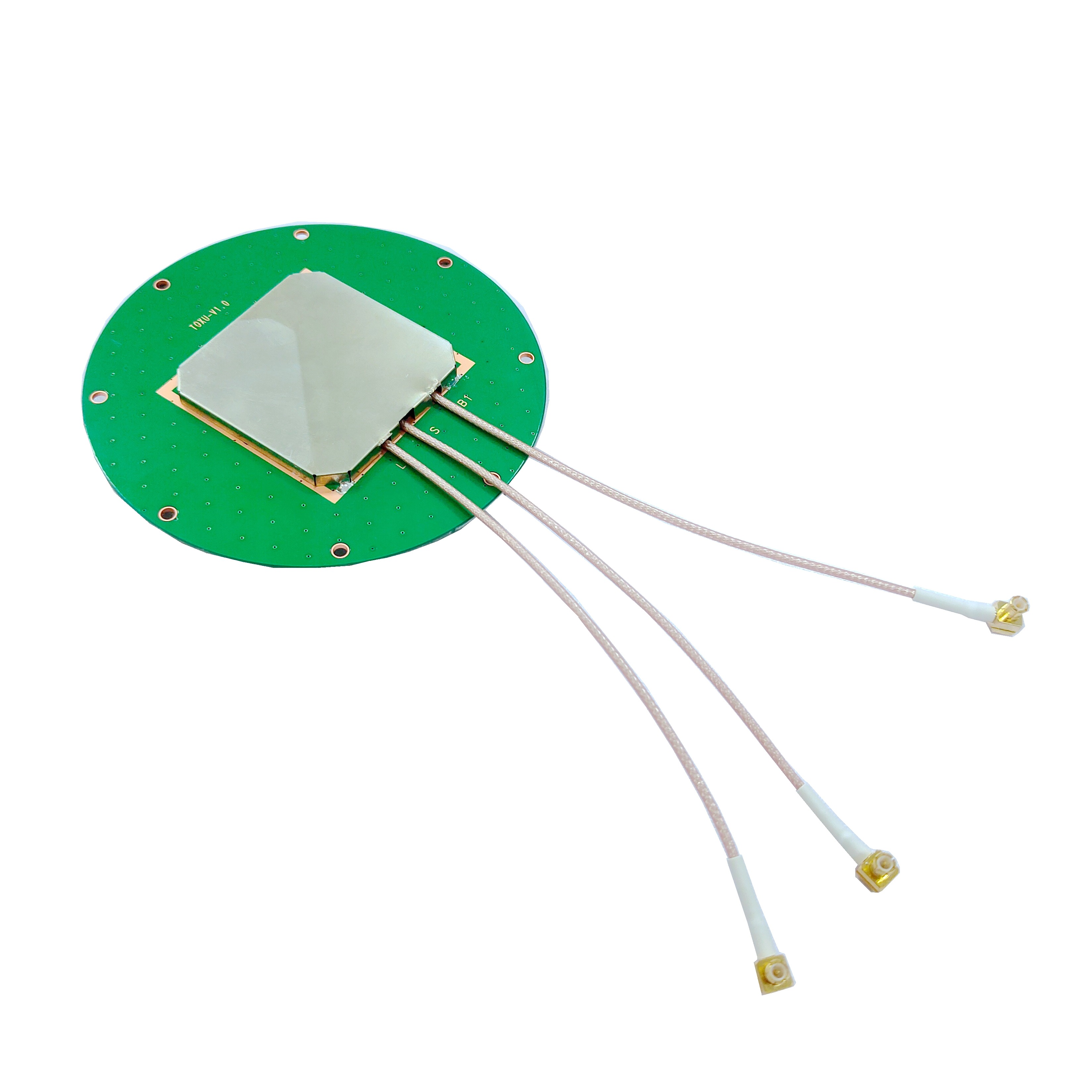
The exceptional performance of a low-noise surveying GNSS antenna is not accidental; it is the result of deliberate and sophisticated design choices and precision manufacturing. Its construction is a complex interplay of radiating elements, ground planes, advanced materials, and integrated electronics.
1. The Radiating Element:
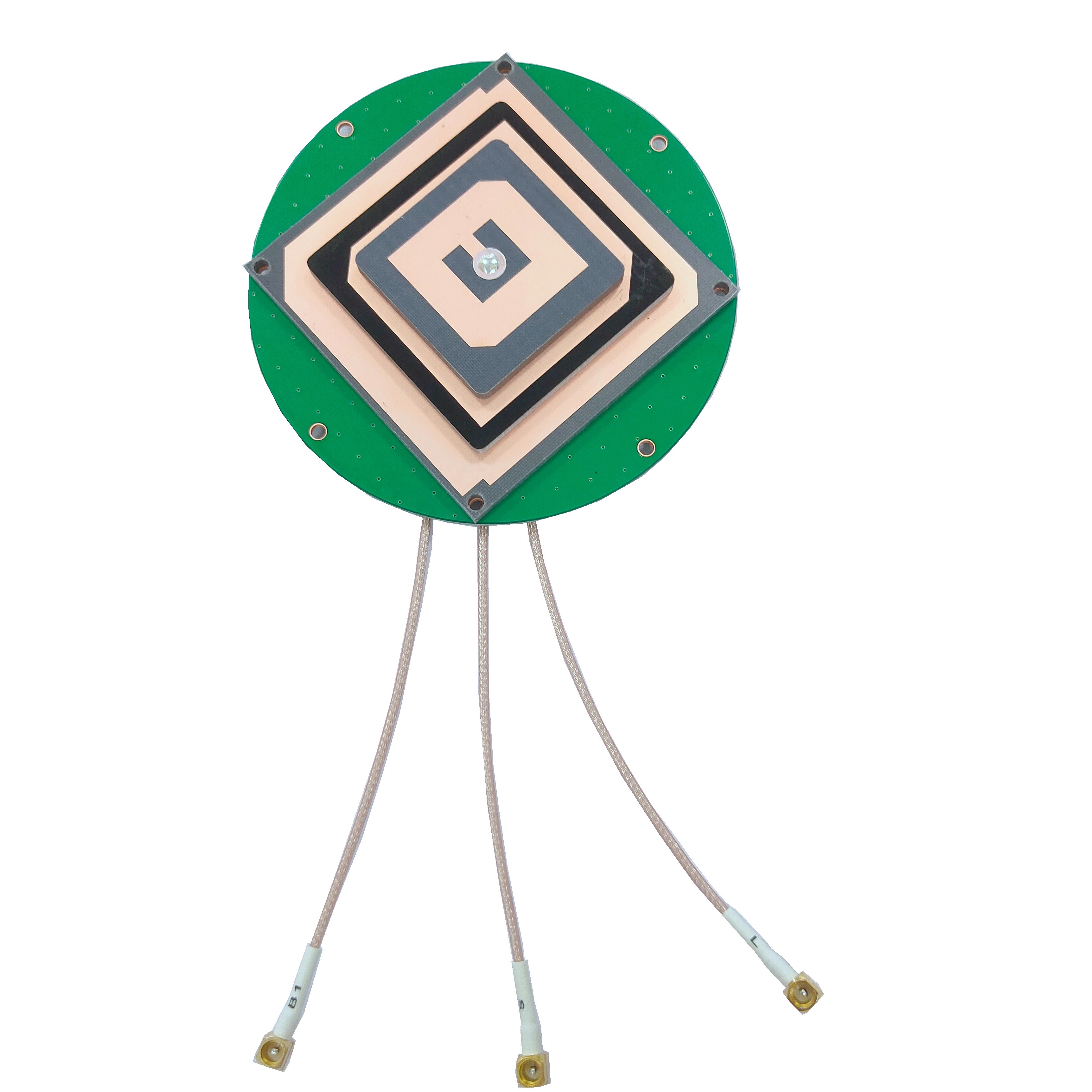
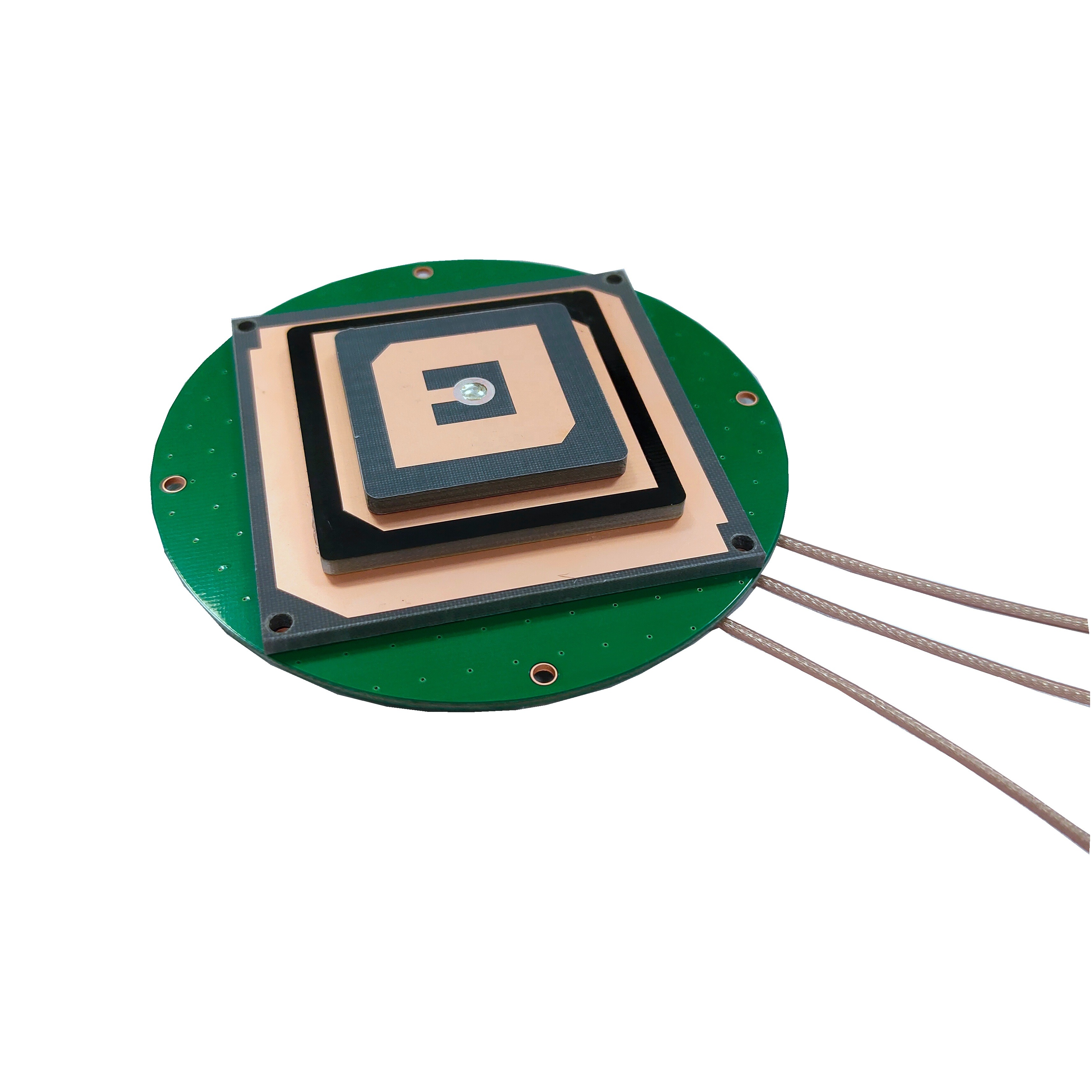
At the heart of the antenna is the element responsible for converting electromagnetic waves into electrical currents. The most common type used is a patch antenna, typically circular or square, etched onto a dielectric substrate. This design is favored for its low profile, mechanical robustness, and ability to produce the required RHCP radiation pattern. More advanced designs may use a spiral or helical element. The material, thickness, and shape of the patch are meticulously calculated to resonate at the specific GNSS frequencies (e.g., ~1575 MHz for L1, ~1227 MHz for L2) with high efficiency.
2. The Ground Plane and Choke Ring:
This is the primary feature that distinguishes a surveying antenna from a consumer one. The radiating element is mounted over a ground plane, a conductive surface that shapes the antenna's radiation pattern. A simple, flat ground plane creates a good upward-looking pattern but is insufficient for multipath rejection.
To achieve superior performance, most high-end antennas incorporate a choke ring. This is a series of concentric, corrugated metal rings surrounding the radiating element. The depth and spacing of these rings are designed to be approximately a quarter-wavelength at the target frequency. This creates a high-impedance surface that effectively "chokes" or suppresses surface currents induced by horizontally polarized waves—the polarization typical of signals reflected from the ground (multipath). The choke ring creates a deep null in the antenna's gain pattern at the horizon and below, dramatically reducing the reception of reflected signals while preserving gain for direct signals from above.
3. The Radome:
The entire assembly is protected by a outer cover called a radome. This is not just a plastic shell; it is an engineered component made from materials like polycarbonate or ceramic-loaded plastics that are specifically chosen for their radio frequency (RF) transparency. The radome must have minimal signal attenuation and a dielectric constant that does not detune the antenna's carefully optimized performance. It also provides environmental protection against water, dust, and UV radiation.
4. The Low-Noise Amplifier (LNA):
Integrated directly into the antenna housing is a critical electronic component: the LNA. Its job is to amplify the faint satellite signals (on the order of -130 dBm) before they are sent down the coaxial cable to the receiver. This is vital because all cables have inherent signal loss (attenuation), which would otherwise make the signals too weak to be useful by the time they reach the receiver. The LNA must have:
Very Low Noise Figure: Typically between 1-3 dB, meaning it adds almost no inherent noise of its own.
High Gain: Usually 25-40 dB, to overcome cable loss.
Linear Operation: It must handle strong out-of-band signals without overloading or creating intermodulation products that could interfere with GNSS reception.
5. Filtering:
Often, bandpass filters are integrated before or after the LNA to reject powerful out-of-band interference from sources like cellular networks (4G/5G), radio, and TV transmitters. This prevents the LNA or the receiver from being desensitized by these strong signals.
6. Phase Center Calibration:
After manufacture, high-precision antennas undergo rigorous testing in an anechoic chamber. Their phase center variation (PCV) is measured across different elevation angles and azimuths. This data is used to create an antenna model file that can be applied during post-processing in software like RTKLIB or in the receiver itself to correct for these known biases, ensuring the phase center is treated as a stable, known point.
The operation of a low-noise surveying GNSS antenna can be understood through the principles of electromagnetic wave reception, frequency selectivity, and noise management.
1. Capturing Right-Hand Circular Polarization (RHCP):
GNSS satellites transmit signals that are right-hand circularly polarized. This means the electric field of the radio wave rotates clockwise as it propagates through space. The antenna's radiating element (e.g., the patch) is designed with specific feed points that excite two orthogonal modes with a 90-degree phase shift between them. This creates a rotating electromagnetic field within the antenna that perfectly matches the incoming RHCP wave, allowing for efficient energy transfer. This design also provides a natural rejection of left-hand circularly polarized (LHCP) waves, which are typically generated by reflections, thus providing a first layer of multipath mitigation.
2. Shaping the Radiation Pattern:
The antenna does not receive signals from all directions equally. Its radiation pattern is intentionally shaped to have high gain at elevations above 5-10 degrees (where satellites are and atmospheric effects are more manageable) and very low gain at and below the horizon. This is achieved through the combination of the radiating element and the ground plane/choke ring assembly. The choke rings work by creating a high-impedance barrier that suppresses surface waves. When a reflected signal (which arrives at a low angle of incidence) tries to induce a current on the ground plane, the choke rings present a very high impedance, effectively blocking the current flow and preventing the antenna from receiving that signal. This pattern is often described as a "hemisphere of gain," focused on the sky.
3. Signal Amplification and Noise Management:
The core of the "low-noise" operation lies in the immediate amplification of the captured signal. The received signal power is extraordinarily weak, often comparable to or below the thermal noise floor (the background noise present in all electronic systems). The integrated LNA amplifies both the desired signal and the ever-present noise. However, because the LNA has a very low noise figure, it adds a minimal amount of additional noise itself. The key metric is the Signal-to-Noise Ratio (SNR). A good LNA preserves the SNR; it amplifies the signal and the incoming noise equally, without significantly degrading the ratio. This amplified signal is then strong enough to be sent through a long cable (which will attenuate both signal and noise) to the receiver, while still maintaining a usable SNR level at the receiver's input.
4. Multi-Frequency Operation:
Modern antennas are designed to be wideband or have multiple resonances to operate across all GNSS frequencies (L1, L2, L5, etc.). This is often achieved using a single radiating element with techniques like stacked patches, where one patch is tuned to a higher frequency (e.g., L1) and is placed above a larger patch tuned to a lower frequency (e.g., L2). This allows one physical antenna to efficiently capture signals across a broad spectrum, enabling advanced error-correction techniques like ionospheric-free positioning.
In essence, the antenna works as a highly selective filter: it spatially filters out multipath via its radiation pattern, frequency filters out out-of-band interference, polarization filters out LHCP reflections, and electronically preserves the SNR through low-noise amplification, delivering a clean, strong signal to the receiver for precise code and, most importantly, carrier-phase measurement.
Advantages:
1. Unmatched Accuracy and Precision: The primary advantage is the enabling of centimeter-to-millimeter level positioning. This is directly due to the stable phase center, which allows for ultra-precise carrier-phase measurements, and the superior multipath rejection, which eliminates a major error source.
2. High Reliability in Difficult Environments: The combination of multipath rejection and a strong LNA makes these antennas highly reliable in challenging environments like urban canyons, areas with heavy foliage, and near reflective surfaces, where consumer-grade systems would fail.
3. Improved Survey Efficiency: By providing cleaner signals and reducing errors from the outset, these antennas reduce the time needed for a surveyor to achieve a fixed, ambiguity-resolved solution. This translates into faster setup times and higher productivity in the field.
4. Support for Advanced Techniques: They are essential for sophisticated GNSS techniques like Real-Time Kinematic (RTK) and Precise Point Positioning (PPP), which are the backbone of modern high-precision applications.
5. Long Baseline Capability: For geodetic networks where reference stations are hundreds of kilometers apart, the phase center stability and low noise performance are non-negotiable for maintaining accuracy over long baselines.
Challenges:
1. Cost: The use of specialized materials (e.g., ceramic substrates, precision-machined choke rings), complex design, rigorous testing, and calibration make these antennas significantly more expensive than their consumer counterparts, often costing thousands of dollars.
2. Size and Weight: The inclusion of a large ground plane or choke ring structure increases the physical size and weight of the antenna. This can be a drawback for applications where portability and low SWaP (Size, Weight, and Power) are critical, such as on drones or wearable equipment.
3. Power Requirements: The integrated LNA requires a power source, which is typically supplied from the receiver through the coaxial cable (phantom power). This adds a power draw to the system.
4. Calibration Dependency: To achieve their stated accuracy, these antennas require accurate antenna phase center variation (PCV) models to be applied in the processing software. Using an incorrect or outdated model can introduce systematic errors.
5. Susceptibility to Interference: While they have filters, extremely strong nearby transmitters can still overload the LNA, causing desensitization or complete loss of lock. The antenna itself cannot distinguish between a legitimate GNSS signal and a malicious jamming signal.
6. Design Complexity for Multi-Constellation/Multi-Frequency: As new signals and constellations are added, designing a single antenna that performs optimally across all required bands (from ~1150 MHz to 1600 MHz) without becoming excessively large or complex is an ongoing engineering challenge.
Applications:
The applications for low-noise surveying GNSS antennas extend far beyond traditional land surveying:
Precision Agriculture: Guiding autonomous tractors for planting, spraying, and harvesting with centimeter accuracy to optimize yield and reduce waste.
Construction and Machine Control: Providing precise positioning for bulldozers, graders, and excavators for grade checking and autonomous earthmoving.
Geodesy and Scientific Monitoring: Monitoring crustal deformation for earthquake and volcano studies, measuring tidal and glacial movement, and contributing to the International Terrestrial Reference Frame (ITRF).
Unmanned Aerial Vehicles (UAVs): Enabling precise navigation and photogrammetry for 3D mapping, infrastructure inspection, and agricultural monitoring.
Autonomous Vehicles: Serving as a primary sensor for localization in self-driving cars, trucks, and marine vessels, often fused with IMUs and other sensors.
Precision Landing Systems: Guiding aircraft for automated landings and drone delivery systems.
Deformation Monitoring: Monitoring the structural health of dams, bridges, skyscrapers, and offshore platforms for minute movements indicating potential failure.
Future Trends:
1. Miniaturization: A major trend is developing high-performance antennas without large choke rings. This involves using Artificial Magnetic Conductor (AMC) surfaces, metasurfaces, and other metamaterials to create compact, low-profile antennas with multipath rejection capabilities rivaling traditional choke rings for SWaP-constrained platforms like drones and consumer devices.
2. Multi-Frequency, Multi-Constellation Ready: Antennas will continue to evolve to cover all current and future signals from GPS (L1C, L2C, L5), Galileo (E1, E5a, E5b, E6), BeiDou (B1, B2, B3), and GLONASS (L1, L2, L3), including the high-precision commercial and safety-of-life services on these bands.
3. Integrated Inertial Measurement Units (IMUs): We will see more antennas with built-in IMUs (accelerometers and gyroscopes) to provide a tightly coupled navigation solution that remains accurate even during GNSS signal outages (e.g., in tunnels or under trees).
4. Anti-Jamming and Anti-Spoofing Integration: Integrating adaptive nulling capabilities directly into the antenna array to electronically steer nulls towards jammers or spoofers, protecting the GNSS system from intentional interference, a growing concern for critical infrastructure.
5. AI-Enhanced Calibration and Operation: Using machine learning to create more dynamic and accurate real-time phase center and multipath correction models that adapt to the immediate environment of the antenna.
6. Cost Reduction: Advances in manufacturing, such as 3D printing of radomes and ground planes, and new design techniques will aim to bring high-precision performance down to a price point accessible for mass-market applications.
Conclusion
The low-noise surveying GNSS antenna is a masterpiece of electromagnetic engineering that sits at the very foundation of modern high-precision positioning. It is a critical differentiator that transforms the ubiquitous capability of GNSS from a meter-level utility into a millimeter-level measurement science. Its sophisticated design, encompassing specialized radiating elements, multipath-mitigating ground planes, ultra-low-noise electronics, and rigorous calibration, is dedicated to a single purpose: capturing the faint whispers of satellite signals with utmost purity and integrity.
While challenges of cost, size, and complexity remain, the relentless drive for higher accuracy in increasingly compact and demanding applications ensures that antenna technology will continue to evolve. The future points towards smarter, smaller, and more integrated systems that will further embed centimeter-accurate positioning into the fabric of our technological world, from the autonomous machines that will build our cities and grow our food to the scientific instruments that monitor the changing dynamics of our planet. In the quest for precision, the antenna will always be the first and most crucial gatekeeper.

 86 0755 2819 9597
Lucy Yang | lucy.y@toxutech.com
Nicole Li | nicole@toxutech.com
Dotty Zhao | sales04@toxutech.com
Global Business Director / Sales Team / Global Operations


 En
En Cn
Cn Korean
 Home >


