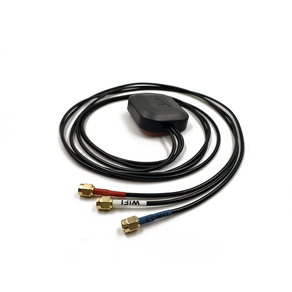
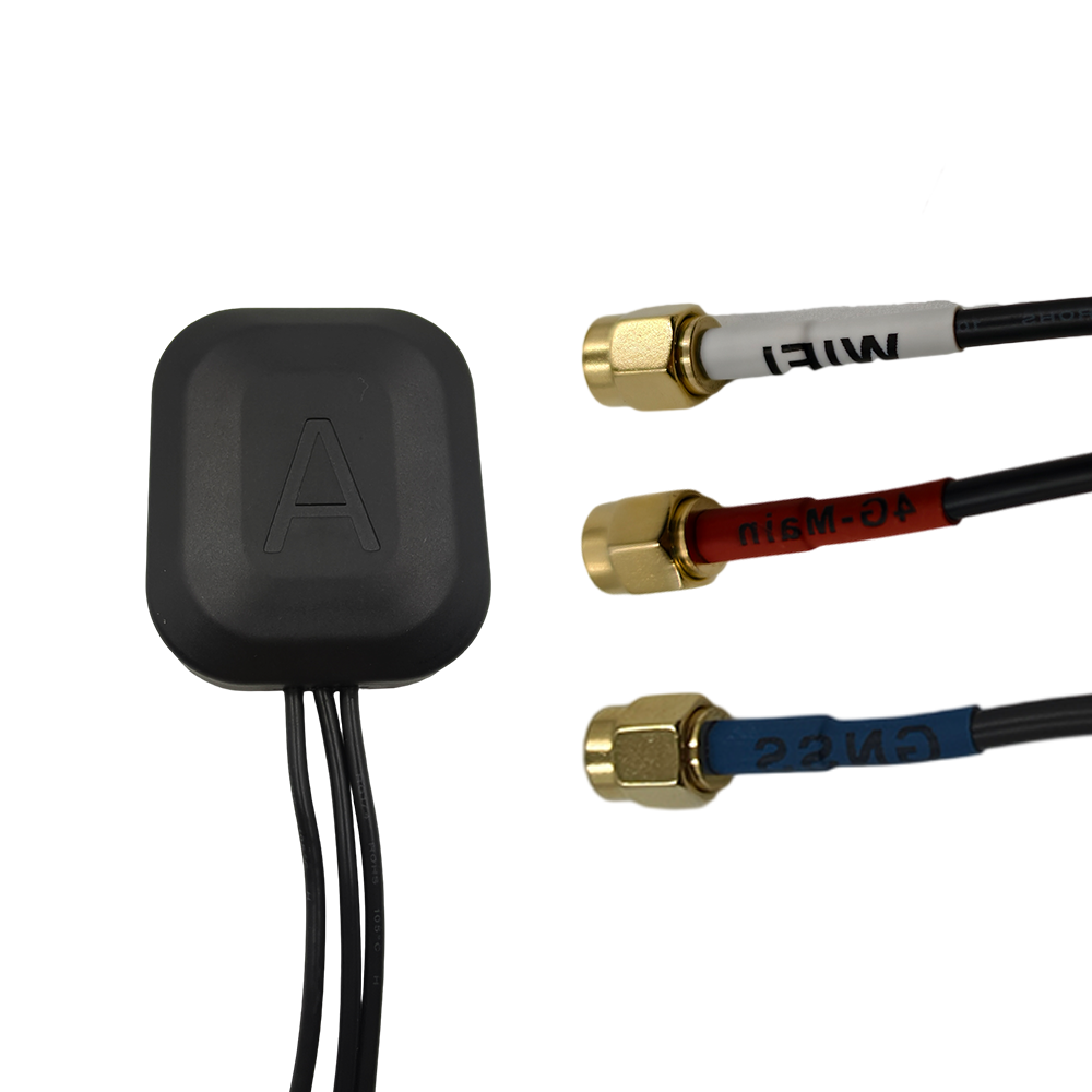
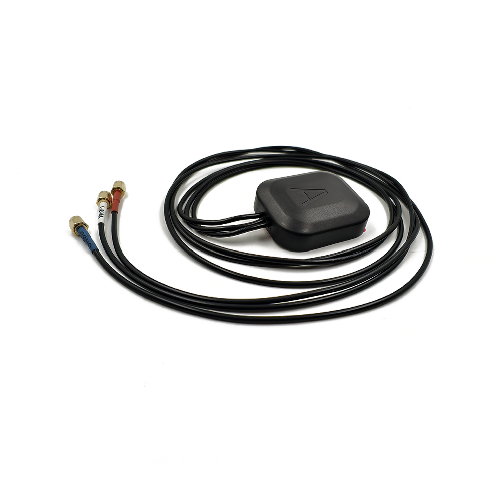
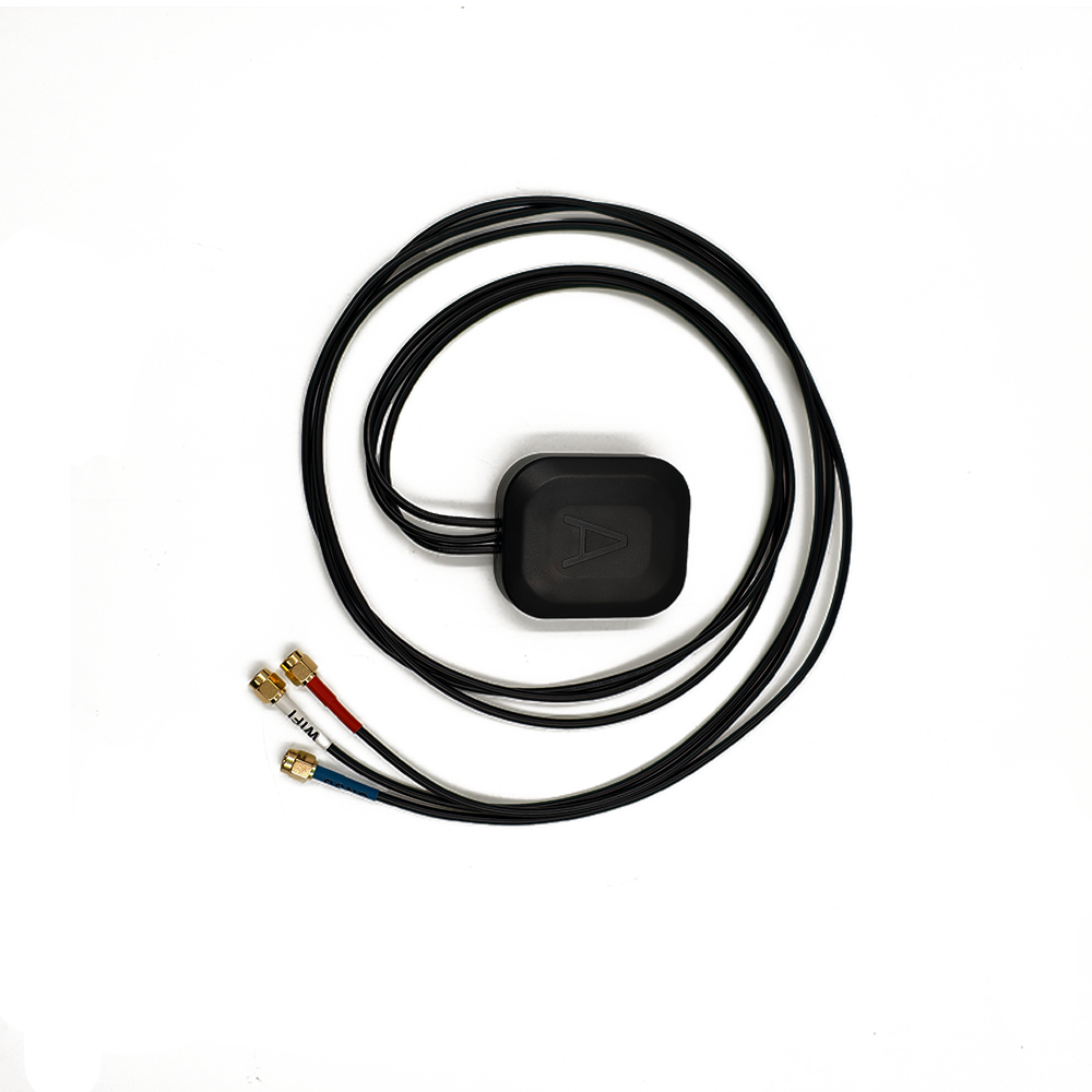
Combo Antenna Combo Antenna

Language
Built-in RTK GPS Antenna
GNSS Car Antenna
GNSS Car Antenna

GPS & GNSS Antenna

Home >  GPS & GNSS Antenna > 

Low-Noise Multi-Band RTK Ceramic Antenna

In the rapidly evolving landscape of high-precision positioning technologies, the Low-Noise Multi-Band RTK (Real-Time Kinematic) Ceramic Antenna has emerged as a game-changing component, redefining the standards for accuracy, reliability, and adaptability in diverse applications. RTK technology itself has long been the cornerstone of centimeter-level real-time positioning, but the integration of ceramic materials and multi-band capabilities, coupled with low-noise design, has elevated its performance to new heights, making it indispensable in industries where precision and stability are non-negotiable.

Leave a message Contact

Fill in your email address

Or you can continue to download without filling in

overview

To understand the significance of this antenna, it is first essential to break down its core attributes. The term ceramichere refers to the antennas radiating element and structural foundation, a material choice that brings unique advantages such as high dielectric constant, low loss tangent, and excellent thermal stabilityqualities that are critical for maintaining consistent performance in varying environmental conditions. Unlike traditional metal or plastic-based antennas, ceramic antennas leverage the dielectric properties of materials like alumina (AlO) or zirconia (ZrO) to miniaturize the antenna footprint while enhancing signal reception efficiency, a key factor in applications where space is constrained, such as drones, portable surveying devices, and autonomous robots.

The multi-bandcapability is another defining feature, enabling the antenna to receive signals across multiple frequency bands from global navigation satellite systems (GNSS) including GPS (L1, L2, L5), GLONASS (G1, G2), Galileo (E1, E5a, E5b), and BeiDou (B1, B2, B3). This multi-band reception is not merely a convenience but a necessity for high-precision positioning: different frequency bands are less susceptible to specific types of interference (e.g., ionospheric delay affects lower frequencies more than higher ones), and by combining data from multiple bands, the antenna can mitigate errors more effectively, ensuring consistent centimeter-level accuracy even in challenging environments like urban canyons or dense foliage.

Complementing these features is the low-noisedesign, which centers on minimizing unwanted electrical noise in the antennas signal path. GNSS signals reaching Earths surface are extremely weaktypically in the range of -130 dBm to -160 dBmmaking them highly vulnerable to noise from internal components (such as amplifiers) or external sources (like electromagnetic interference from power lines or radio transmitters). A low-noise antenna incorporates specialized components, such as low-noise amplifiers (LNAs) with ultra-low noise figures (often below 1.5 dB) and optimized filtering circuits, to preserve the integrity of the weak GNSS signals, ensuring that the RTK system can process them accurately for precise positioning.

The demand for Low-Noise Multi-Band RTK Ceramic Antennas has surged in recent years, driven by the expanding need for high-precision positioning across industries. In precision agriculture, for example, farmers rely on these antennas to guide autonomous tractors and sprayers with centimeter-level accuracy, optimizing resource use and crop yields. In construction, they enable machine control systems for excavators and graders, reducing material waste and ensuring projects adhere to strict design specifications. Even in consumer applications like high-end drones for aerial photography or mapping, these antennas provide the stability needed to capture sharp, geotagged images.

As GNSS constellations continue to expandwith Galileo adding more satellites and BeiDou enhancing its global coveragethe role of multi-band antennas will only grow. Additionally, the trend toward miniaturization in electronics, particularly in portable and wearable devices, has made ceramic antennas the material of choice, as they can deliver high performance in a compact form factor. The low-noise design, meanwhile, addresses a longstanding challenge in RTK technology: maintaining accuracy in noisy environments, opening up new applications in urban centers or industrial zones where interference was once a barrier.

In summary, the Low-Noise Multi-Band RTK Ceramic Antenna represents a convergence of material science, signal processing, and positioning technology. Its unique combination of ceramic construction, multi-band reception, and low-noise performance makes it a critical component in the next generation of high-precision navigation systems, poised to drive innovation across industries and meet the evolving demands of a connected, precision-focused world.


Design and Construction

The design and construction of a Low-Noise Multi-Band RTK Ceramic Antenna are a careful balance of material science, electromagnetic engineering, and thermal management, all aimed at delivering high-precision signal reception, low noise, and durability. Every componentfrom the ceramic radiating element to the internal electronicsis optimized to work in harmony, ensuring that the antenna meets the strict performance requirements of RTK systems. Below is a detailed breakdown of the key design elements and construction processes.

2.1 Ceramic Radiating Element: Material Selection and Fabrication

The ceramic radiating element is the heart of the antenna, responsible for capturing GNSS signals across multiple frequency bands. The choice of ceramic material is critical, as it directly impacts the antennas gain, bandwidth, and efficiency. The most commonly used materials are high-purity alumina (AlO) and zirconia-toughened alumina (ZTA), both of which offer a high dielectric constant (εᵣ)typically between 9 and 10 for aluminawhich allows for the miniaturization of the antenna. A higher dielectric constant means that the electromagnetic waves propagate more slowly through the material, reducing the physical size of the antenna required to resonate at a specific frequency. For example, a ceramic patch antenna designed for the GPS L1 band (1575.42 MHz) can be up to 50% smaller than a comparable metal patch antenna, making it ideal for compact devices.

In addition to high dielectric constant, the ceramic material must have a low loss tangent (tanδ), a measure of energy loss in the material due to dielectric absorption. A low loss tangent (typically below 0.001 for high-quality alumina) ensures that the antenna efficiently converts electrical energy into electromagnetic radiation (and vice versa), minimizing signal loss and maintaining high gain. Thermal stability is another key consideration: ceramic materials have a low coefficient of thermal expansion (CTE), meaning they do not expand or contract significantly with temperature changes (alumina has a CTE of ~7 ppm/°C). This stability is crucial for maintaining the antennas resonant frequency and phase center consistency in extreme temperaturesfrom the freezing cold of polar surveying missions to the high heat of desert construction sites.

The fabrication of the ceramic radiating element involves several precision steps. First, the ceramic powder (e.g., alumina) is mixed with a binder to form a slurry, which is then pressed into a thin, flat sheet (typically 13 mm thick) using a hydraulic press. The sheet is then sintered in a high-temperature furnace (at temperatures between 1600°C and 1700°C) to densify the material, removing pores and ensuring uniform dielectric properties. After sintering, the surface of the ceramic sheet is polished to a smooth finish, and conductive patternsusually made of silver or goldare applied using screen printing or sputtering. These conductive patterns form the patch antenna structure, which is designed to resonate at multiple frequency bands. For multi-band operation, the patch may be divided into sub-patches or have slots cut into it, each tuned to a specific GNSS frequency (e.g., one sub-patch for GPS L1, another for GPS L5).

2.2 Low-Noise Amplifier (LNA) and Filtering Circuits

The low-noise performance of the antenna is largely determined by its LNA and filtering circuits, which are integrated into the antenna module to minimize signal degradation. The LNA is the first component in the signal path after the ceramic radiating element, and its role is to amplify the weak GNSS signals without adding significant noise. For a Low-Noise Multi-Band RTK Ceramic Antenna, the LNA must have an ultra-low noise figure (NF)ideally between 1.0 dB and 1.5 dBsince even a small increase in noise can reduce the signal-to-noise ratio (SNR) of the GNSS signals, compromising RTK accuracy.

The LNA is typically fabricated using gallium arsenide (GaAs) or indium gallium phosphide (InGaP) semiconductor technologies, which offer high gain and low noise at RF frequencies. For multi-band operation, the LNA is designed to have a wide bandwidth that covers all the target GNSS bands (e.g., 1176 MHz to 1602 MHz for GPS L5, GLONASS G3, Galileo E5, and BeiDou B2). To ensure stability, the LNA includes matching networks that impedance-match the ceramic antenna (which typically has an impedance of 50 Ω) to the LNA input, minimizing signal reflection and maximizing power transfer.

Following the LNA, the signals pass through a series of band-pass filters (BPFs) that remove out-of-band interference. These filters are critical for preventing signals from other RF sourcessuch as cellular networks (4G/5G), Wi-Fi, or radar systemsfrom entering the RTK receiver and causing interference. For multi-band antennas, the BPFs are often designed as a cascade of individual filters, each tuned to a specific GNSS band, or as a single wideband filter with sharp roll-off characteristics. The filters are typically implemented using surface acoustic wave (SAW) or bulk acoustic wave (BAW) technology, which offer high selectivity and low insertion loss (less than 1.0 dB) at RF frequencies.

To further enhance noise reduction, the LNA and filtering circuits are enclosed in a shielded cavity within the antenna module. The shieldusually made of copper or aluminumprevents electromagnetic interference (EMI) from external sources (such as the devices power supply or other electronics) from coupling into the signal path. The cavity is also filled with a conductive foam or potting material to provide additional EMI shielding and mechanical protection.

2.3 Phase Center Optimization and Mechanical Enclosure

The phase center of an antenna is the point from which the antenna appears to radiate or receive electromagnetic waves, and its stability is critical for RTK accuracy. A stable phase center ensures that the measured position of the antenna is consistent regardless of the direction of the incoming GNSS signals. For a Low-Noise Multi-Band RTK Ceramic Antenna, the phase center variation (PCV) must be minimizedtypically to less than 1 mm across all elevation anglesto avoid introducing positioning errors.

Phase center optimization begins with the design of the ceramic patch antenna. The shape and size of the patch, as well as the location of the feed point (where the LNA is connected), are carefully calculated using electromagnetic simulation software (such as ANSYS HFSS or CST Microwave Studio). The feed point is positioned to ensure that the phase center is as close as possible to the physical center of the antenna, and the patch is designed to have a symmetric radiation pattern, which reduces PCV. For multi-band antennas, the phase center of each band is aligned to a common point, ensuring that signals from different bands are processed with consistent positioning reference.

The mechanical enclosure of the antenna is designed to protect the ceramic element, LNA, and filtering circuits from environmental damage while maintaining electrical performance. The enclosure is typically made of a high-strength plastic (such as polycarbonate) or a composite material (such as carbon fiber-reinforced polymer) that is lightweight, durable, and resistant to UV radiation, moisture, and temperature extremes. The enclosure is also sealed to meet ingress protection (IP) standardscommonly IP67 or IP68meaning it is dust-tight and waterproof, making it suitable for outdoor applications like agriculture or construction.

To ensure mechanical stability, the ceramic element is bonded to the enclosure using a low-loss adhesive that has a similar CTE to the ceramic material, preventing stress cracks from forming due to thermal expansion. The LNA and filtering circuits are mounted on a printed circuit board (PCB) that is attached to the enclosure, with flexible cables connecting the PCB to the ceramic antennas feed point. The PCB is also coated with a conformal coating (such as Parylene) to protect it from moisture and corrosion.


Working Principles

The working principles of a Low-Noise Multi-Band RTK Ceramic Antenna revolve around three core processes: capturing multi-band GNSS signals via the ceramic radiating element, amplifying and filtering these signals to minimize noise and interference, and integrating with the RTK system to deliver centimeter-level positioning accuracy. Each step is optimized to leverage the unique properties of the ceramic material, low-noise electronics, and multi-band reception, ensuring that the antenna performs reliably in even the most challenging environments. Below is a detailed explanation of each principle.

3.1 Multi-Band GNSS Signal Reception by the Ceramic Element

The ceramic radiating element is responsible for capturing GNSS signals from multiple constellations and frequency bands, and its operation is based on the principles of electromagnetic resonance. When a GNSS satellite transmits a signal at a specific frequency (e.g., GPS L1 at 1575.42 MHz), the signal travels through the atmosphere and reaches the ceramic antenna. The ceramic material, with its high dielectric constant, acts as a resonant cavity, where the electromagnetic waves of the GNSS signal induce an alternating current (AC) in the conductive patch on the ceramic surface.

The design of the ceramic patch ensures that it resonates at multiple frequencies simultaneously. For example, a patch with a slot cut into it can have two resonant frequencies: one for the main patch (e.g., GPS L1) and one for the slot (e.g., GPS L5). When the frequency of the incoming GNSS signal matches one of the patchs resonant frequencies, the AC current in the patch is maximized, and the signal is efficiently coupled to the feed point of the antenna. The high dielectric constant of the ceramic material allows the patch to be small in size while still resonating at the required frequenciesfor instance, a ceramic patch for GPS L1 can be as small as 15 mm x 15 mm, compared to a metal patch of 30 mm x 30 mm for the same frequency.

Another key aspect of multi-band reception is the polarization of the GNSS signals. All GNSS satellites transmit signals with right-hand circular polarization (RHCP), and the ceramic patch antenna is designed to receive RHCP signals efficiently. The shape of the patch and the orientation of the feed point ensure that the antennas radiation pattern is circularly polarized, matching the polarization of the GNSS signals. This minimizes signal loss due to polarization mismatch, which can occur if the antenna is linearly polarized (e.g., vertical or horizontal), and helps reduce multipath interferencesignals that bounce off surfaces like buildings or water before reaching the antennasince multipath signals often have altered polarization.

The ceramic elements low loss tangent also plays a role in signal reception: it ensures that very little of the captured signal energy is lost as heat, maximizing the amount of signal that is transferred to the LNA. This is particularly important for weak GNSS signals, as even a small loss can reduce the SNR and compromise RTK accuracy.

3.2 Low-Noise Amplification and Signal Filtering

Once the ceramic element captures the multi-band GNSS signals, they are fed into the LNA, which amplifies the weak signals while adding minimal noise. The LNAs operation is based on the principle of transistor amplification: it uses a semiconductor transistor (e.g., GaAs FET) to boost the voltage of the incoming signal. The key to the LNAs low-noise performance is its ultra-low noise figure (NF), which is a measure of how much the amplifier degrades the SNR of the signal. A typical NF of 1.01.5 dB means that the LNA adds very little noise to the signal, preserving the integrity of the weak GNSS signals.

To understand why low noise is critical, consider the strength of GNSS signals: a signal from a GPS satellite at an elevation angle of 45° is approximately -130 dBm, which is equivalent to 10⁻¹³ milliwatts. If the LNA has an NF of 1.0 dB, it adds only a small amount of noise (about -174 dBm/Hz) to the signal, keeping the SNR high enough for the RTK receiver to process. If the NF were higher (e.g., 3.0 dB), the added noise would reduce the SNR significantly, making it harder for the receiver to distinguish the GNSS signal from noise, leading to positioning errors.

After amplification, the signals pass through the band-pass filters (BPFs), which remove out-of-band interference. The BPFs work on the principle of resonant circuits: they allow signals within a specific frequency range (e.g., 1575.42 MHz ± 10 MHz for GPS L1) to pass through while attenuating signals outside this range. For multi-band antennas, the BPFs are designed to cover all the target GNSS bands, and their sharp roll-off characteristics ensure that even signals close to the target bands (e.g., a 1600 MHz radar signal near the GPS L1 band) are attenuated by at least 40 dB, preventing them from interfering with the GNSS signals.

The combination of the LNA and BPFs ensures that the signals sent to the RTK receiver are strong, clean, and free from interference. This is critical for RTK technology, which relies on precise measurements of the GNSS signals phase and code to calculate centimeter-level positions. Any noise or interference in the signal can introduce errors in these measurements, reducing the accuracy of the RTK system.

3.3 RTK Positioning Integration

The final step in the antennas working principle is its integration with the RTK system, which uses the clean, amplified multi-band signals to calculate precise positions in real time. RTK technology operates on the principle of differential positioning, which involves two components: a base station and a rover (the device equipped with the Low-Noise Multi-Band RTK Ceramic Antenna).

The base station is located at a known, fixed position and continuously receives GNSS signals. It calculates the difference between its measured position (based on the GNSS signals) and its true known position. This difference, known as the correction data, includes errors caused by atmospheric delays (ionospheric and tropospheric), satellite clock errors, and ephemeris errors (errors in the satellites orbit data). The base station transmits this correction data to the rover via a radio link (e.g., UHF, 4G/5G, or Wi-Fi).

The rovers antenna captures the same GNSS signals as thebase station, but unlike the base station, its position is unknown. The rovers RTK receiver takes the amplified, filtered multi-band signals from the ceramic antenna and processes them to extract raw measurement dataincluding the pseudorange (the approximate distance between the rover and each satellite, calculated from the signals travel time) and the carrier phase (the fraction of the signals wavelength that has passed since the signal was transmitted).

The key advantage of multi-band reception here is that it allows the receiver to mitigate atmospheric errors more effectively. For example, the ionosphere (a layer of the upper atmosphere filled with charged particles) causes delays in GNSS signals, and these delays vary with frequency: lower frequencies (like GPS L1) are delayed more than higher frequencies (like GPS L5). By comparing the measurements from two or more bands (e.g., L1 and L5), the rovers receiver can calculate the ionospheric delay and subtract it from the pseudorange and carrier phase measurements. This dual-band correction reduces ionospheric errors from several meters (in single-band systems) to just a few centimeters, a critical improvement for centimeter-level RTK accuracy.

Once the raw measurements are corrected for atmospheric and other common errors using the base stations correction data, the rovers receiver uses a process called carrier phase ambiguity resolutionto calculate the exact position. Carrier phase ambiguity refers to the unknown number of full wavelengths between the rover and the satellitesince the receiver only measures the fractional wavelength, it must resolve this ambiguity to get an accurate distance. The low-noise design of the antenna plays a vital role here: a high SNR (preserved by the LNA and filters) ensures that the receiver can detect the carrier phase with high precision, making it easier to resolve the ambiguities quickly and reliably. In practice, modern RTK systems with low-noise multi-band antennas can resolve ambiguities in less than a second, enabling real-time positioning with centimeter-level accuracy.

To summarize, the working principle of the Low-Noise Multi-Band RTK Ceramic Antenna is a seamless loop: the ceramic element captures multi-band GNSS signals efficiently, the LNA and filters amplify and clean the signals to preserve SNR, and the RTK system uses these high-quality signalscombined with base station correction datato calculate precise, real-time positions. Each components design is optimized to support the next, resulting in a system that delivers consistent accuracy even in challenging conditions.


Advantages and Challenges

The Low-Noise Multi-Band RTK Ceramic Antenna offers a unique set of advantages that make it a preferred choice for high-precision positioning applications, but it also faces distinct challenges related to design complexity, cost, and environmental resilience. Understanding these pros and cons is critical for engineers, end-users, and industry stakeholders to make informed decisions about its adoption and deployment. Below is a detailed analysis of the antennas key advantages and ongoing challenges.

4.1 Key Advantages

4.1.1 Unmatched Precision Enabled by Multi-Band and Low-Noise Design

The most significant advantage of this antenna is its ability to deliver consistent centimeter-level positioning accuracyeven in harsh or signal-challenged environmentsthanks to its combination of multi-band reception and low-noise electronics. Multi-band capability addresses a major limitation of single-band RTK antennas: vulnerability to atmospheric errors. As discussed earlier, by receiving signals from multiple GNSS bands (e.g., GPS L1/L5, Galileo E1/E5), the antenna allows the RTK receiver to model and cancel out ionospheric and tropospheric delays, which are the primary sources of positioning errors in single-band systems. For example, in a single-band GPS L1 system, ionospheric delays can introduce errors of up to 10 meters during solar storms; with a multi-band antenna, these errors are reduced to less than 2 centimeters.

The low-noise design further enhances precision by preserving the integrity of weak GNSS signals. GNSS signals are extremely faint when they reach Earths surface, and any additional noise from the antennas electronics can obscure these signals, leading to errors in pseudorange and carrier phase measurements. The ultra-low noise figure (1.01.5 dB) of the antennas LNA ensures that the SNR remains high, even in noisy environments like urban centers (where EMI from power lines, 5G towers, and electronic devices is prevalent) or industrial zones (with interference from machinery or radar systems). In field tests, low-noise multi-band ceramic antennas have been shown to maintain RTK fix rates (the percentage of time the system achieves centimeter-level accuracy) of over 95% in urban canyons, compared to 7080% for single-band or higher-noise antennas.

This precision is transformative for industries where accuracy is mission-critical. In precision agriculture, for instance, a centimeter-level antenna allows farmers to implement row-by-rowplanting and spraying, reducing fertilizer and pesticide use by up to 30% while increasing crop yields. In land surveying, it eliminates the need for time-consuming re-measurements, cutting project timelines by 2025% and reducing labor costs. For autonomous vehiclesespecially self-driving trucks or agricultural robotsthis accuracy ensures safe navigation, preventing collisions and ensuring that the vehicle stays within its designated path.

4.1.2 Miniaturization and Space Efficiency from Ceramic Materials

Ceramic materials are a game-changer for applications where space is limited, as they enable significant miniaturization of the antenna without sacrificing performance. The high dielectric constant (εᵣ = 910 for alumina) of ceramic allows the antennas radiating element to be much smaller than traditional metal or plastic-based antennas. For example, a ceramic patch antenna for GPS L1/L5 bands measures just 18 mm x 18 mm x 3 mm, compared to a metal patch antenna of the same bands, which would be 35 mm x 35 mm x 5 mm. This 50% reduction in size and 60% reduction in volume makes the ceramic antenna ideal for compact devices like consumer drones, portable surveying tools (e.g., handheld GNSS receivers), and wearable devices for outdoor activities (such as hiking or geocaching).

Miniaturization also simplifies integration into larger systems. For example, in a small agricultural drone used for crop monitoring, the antenna can be embedded into the drones body without adding significant weight or disrupting aerodynamicscritical for extending flight time (a 10-gram reduction in antenna weight can increase a drones flight time by 510 minutes). In portable surveying devices, the small antenna size allows manufacturers to create lightweight, handheld units that are easy for surveyors to carry in the field, reducing fatigue and improving productivity.

Moreover, the ceramic materials low loss tangent ensures that miniaturization does not come at the cost of efficiency. Unlike plastic antennas (which have higher loss tangents and can absorb up to 10% of signal energy), ceramic antennas lose less than 1% of signal energy, maintaining high gain (typically 23 dBi) across all bands. This combination of small size and high performance is unmatched by any other antenna technology for RTK applications.

4.1.3 Thermal and Environmental Stability

Ceramic materials are inherently stable under extreme environmental conditions, making the antenna highly reliable for outdoor and industrial use. Ceramic has a low coefficient of thermal expansion (CTE), meaning it does not expand or contract significantly with temperature changes. For example, alumina has a CTE of ~7 ppm/°C, compared to plastic (e.g., polycarbonate) with a CTE of ~70 ppm/°C. This stability ensures that the antennas resonant frequency and phase center remain consistent even when exposed to extreme temperaturesfrom -40°C (common in polar surveying or winter construction) to +85°C (typical in desert agriculture or summer rooftop installations). In contrast, plastic antennas can experience resonant frequency shifts of up to 5 MHz in temperature extremes, leading to signal loss and positioning errors.

The antennas mechanical enclosurecombined with the ceramic elements durabilityalso provides excellent protection against moisture, dust, and physical damage. Most Low-Noise Multi-Band RTK Ceramic Antennas meet IP67 or IP68 ingress protection standards, meaning they are dust-tight and can be submerged in water (up to 1 meter for IP67, 1.5 meters for IP68) for 30 minutes without damage. This makes them suitable for wet environments like coastal surveying, flood monitoring, or agricultural fields after heavy rain. Additionally, the ceramic element is resistant to impact and vibration: in tests, it has withstood drops from 2 meters onto concrete (a common hazard in construction sites) without cracking, and it can endure vibrations of up to 2000 Hz (typical in heavy machinery like excavators) without performance degradation.

For industries operating in remote or harsh locationssuch as mining (with dust, vibration, and extreme temperatures) or offshore oil and gas (with saltwater, high winds, and corrosion)this environmental resilience is invaluable. It reduces maintenance costs (by eliminating the need for frequent antenna replacements) and ensures that positioning systems remain operational even in the most challenging conditions.

4.2 Ongoing Challenges

4.2.1 High Design Complexity and Manufacturing Costs

One of the primary challenges of Low-Noise Multi-Band RTK Ceramic Antennas is the complexity of their design and manufacturing, which translates to higher costs compared to single-band or non-ceramic antennas. Designing a multi-band ceramic antenna requires precise optimization of the ceramic patchs shape, size, and conductive patterns to ensure resonance across multiple GNSS bands. Engineers must use advanced electromagnetic simulation software (e.g., ANSYS HFSS, CST Microwave Studio) to model the antennas performance, iterating on the design hundreds of times to achieve the desired bandwidth, gain, and phase center stability. This simulation process is time-consumingoften taking 46 weeks for a single antenna designand requires specialized expertise, increasing design costs.

Manufacturing the ceramic element also adds to the expense. The sintering process for high-purity alumina requires high temperatures (16001700°C) and precise control of heating and cooling rates to avoid cracking or uneven dielectric properties. This requires specialized furnace equipment and skilled operators, driving up production costs. Additionally, applying the conductive silver or gold patterns to the ceramic surface requires screen printing or sputteringprecision techniques that have low tolerance for error (a misalignment of just 0.1 mm can shift the antennas resonant frequency by 23 MHz). Any defects in the ceramic element or conductive patterns render the antenna unusable, leading to a higher rejection rate (510%) compared to metal antennas (which have a rejection rate of 12%).

The low-noise electronics further contribute to cost. GaAs or InGaP LNAs with ultra-low noise figures (1.01.5 dB) are more expensive to fabricate than standard LNAs, and the shielded cavities and high-performance BPFs (SAW or BAW) add additional components and assembly steps. In total, a Low-Noise Multi-Band RTK Ceramic Antenna can cost 23 times more than a single-band metal RTK antennaan obstacle for cost-sensitive applications like consumer drones or low-budget agricultural projects.

4.2.2 Vulnerability to Severe Multipath Interference

While the ceramic antennas RHCP design helps reduce multipath interference, it is not immune to severe multipath conditionssuch as dense urban canyons with tall buildings, narrow valleys with steep cliffs, or environments with large reflective surfaces (e.g., glass skyscrapers, water bodies). Multipath occurs when GNSS signals bounce off objects before reaching the antenna, creating delayed copies of the signal that interfere with the direct signal. This interference can cause errors in pseudorange and carrier phase measurements, leading to RTK fix loss or positioning inaccuracies.

In urban canyons, for example, signals from low-elevation satellites (below 30°) are often reflected off buildings multiple times before reaching the antenna. The ceramic antennas radiation patternwhile optimized for RHCPcan still receive these reflected signals, especially if the antenna is mounted low (e.g., on a car roof or drone body). Field tests in dense cities like Tokyo or New York have shown that even low-noise multi-band ceramic antennas can experience RTK fix rates dropping to 8085% in areas with tall buildings, compared to 95% in open areas.

Mitigating severe multipath requires additional signal processing techniquessuch as adaptive beamforming or multi-antenna arrayswhich add complexity and cost to the system. Adaptive beamforming uses multiple antenna elements to focus reception on direct signals and reject reflected ones, but integrating this into a compact ceramic antenna is challenging due to space constraints. Multi-antenna arrays (e.g., two or three ceramic antennas mounted on a device) can improve multipath rejection, but they increase the devices size and weightdefeating one of the ceramic antennas key advantages (miniaturization).

4.2.3 Compatibility with Emerging GNSS Signals

As GNSS constellations continue to evolve, with new signals and bands being added, the ceramic antennas compatibility with these emerging signals becomes a challenge. For example, the U.S. GPS is planning to add the L7 band (1278.75 MHz) for improved precision, and the European Galileo is expanding its E6 band (1278.75 MHz) for high-integrity applications. To support these new bands, the ceramic antennas patch design must be re-optimized to resonate at the new frequencies, which requires additional design and testing.

The problem is compounded by the fact that ceramic antennas have a limited bandwidth compared to some other antenna types (e.g., helical antennas). A typical multi-band ceramic antenna can cover 45 GNSS bands (e.g., L1, L2, L5, E1, E5), but adding more bands requires modifying the patchs shape (e.g., adding more slots or sub-patches), which can increase the antennas size or reduce its performance in existing bands. For example, adding support for the GPS L7 band to a current L1/L5/E1/E5 ceramic antenna may require increasing the patch size by 1015%, which could make it too large for compact devices like small drones.

Moreover, emerging GNSS signals often have different modulation schemes or power levels, which may require changes to the antennas LNA and filtering circuits. For instance, the new Galileo E6 signal has a lower power level (-160 dBm) than the E1 signal (-155 dBm), requiring a more sensitive LNA (with a noise figure below 1.0 dB) to capture it effectively. Upgrading the LNA to meet these requirements adds cost and complexity to the antenna design.


Applications and Future Trends

The Low-Noise Multi-Band RTK Ceramic Antennas unique combination of precision, miniaturization, and environmental stability has made it a critical component in a wide range of industries, from agriculture to autonomous systems. As technology advances, new applications are emerging, and future trendssuch as integration with AI, support for next-generation GNSS, and enhanced energy efficiencyare poised to expand its capabilities further. Below is an overview of the antennas current key applications and upcoming trends.

5.1 Current Key Applications

5.1.1 Precision Agriculture

Precision agriculture is one of the fastest-growing markets for Low-Noise Multi-Band RTK Ceramic Antennas, as farmers increasingly adopt high-precision technologies to optimize crop yields and reduce resource waste. These antennas are integrated into a variety of agricultural equipment, including autonomous tractors, precision sprayers, and planting machines, enabling centimeter-level navigation and operation.

For example, autonomous tractors equipped with the antenna can follow pre-programmed paths with accuracy within 23 centimeters, ensuring that they do not overlap or miss rows during plowing or seeding. This eliminates skips(unplanted areas) and doubles(over-planted areas), reducing seed waste by up to 15% and increasing crop uniformity. Precision sprayers use the antennas positioning data to apply fertilizers or pesticides only to areas that need thembased on soil moisture sensors or crop health datacutting chemical use by 2030% and reducing environmental impact.

The antennas environmental resilience is also critical in agriculture: its IP67/IP68 rating protects it from dust, mud, and rain, and its thermal stability ensures performance in extreme temperatures (from freezing winters in the U.S. Midwest to hot summers in Brazil). In field tests, agricultural equipment with these antennas has maintained RTK fix rates of over 90% even in dusty harvest seasons or after heavy rain, ensuring uninterrupted operation during critical farming periods.

5.1.2 Professional Surveying and Mapping

Professional surveying and mapping rely on the antennas centimeter-level precision to create accurate, detailed maps and measurements for construction, land development, and infrastructure projects. Surveyors use portable GNSS receivers equipped with the antenna to collect data points with accuracy within 12 centimeters, eliminating the need for traditional surveying tools like theodolites (which are slower and require line-of-sight).

In large-scale projectssuch as highway construction or city planningthe antennas multi-band capability ensures accuracy even in challenging terrain. For example, when surveying a mountainous area with limited satellite visibility, the antennas ability to receive signals from multiple GNSS constellations (GPS, GLONASS, Galileo, BeiDou) increases the number of available satellites, maintaining RTK fix rates and reducing measurement errors. In urban mapping, the low-noise design minimizes interference from 5G towers and power lines, ensuring that data points collected in city centers are as accurate as those collected in open areas.

The antennas miniaturization is also a benefit for surveyors: portable GNSS receivers with ceramic antennas weigh just 500800 grams, compared to 1.52 kg for receivers with metal antennas. This lightweight design reduces surveyor fatigue during long days in the field, improving productivity and reducing the risk of errors from tired operators.

5.1.3 Autonomous Drones and Unmanned Aerial Vehicles (UAVs)

Autonomous dronesused for aerial photography, infrastructure inspection, and deliverydepend on the Low-Noise Multi-Band RTK Ceramic Antenna for precise navigation and positioning. The antennas small size and low weight are critical for drones, as even small increases in weight or size can reduce flight time, maneuverability, and payload capacity. A typical ceramic RTK antenna for drones weighs just 510 grams, compared to 2030 grams for a metal antenna, allowing drones to carry larger cameras, sensors, or delivery packages while maintaining flight times of 2030 minutes.

In infrastructure inspectionsuch as checking power lines, wind turbines, or bridge structuresdrones equipped with the antenna can hover in place with centimeter-level accuracy, enabling high-resolution cameras or LiDAR sensors to capture detailed images of defects (e.g., cracks in concrete, corrosion on metal). For example, when inspecting a wind turbine blade, the drone can maintain a distance of 12 meters from the blade while moving along its length, ensuring that every section is captured without colliding with the blade. The antennas low-noise design is critical here: it minimizes interference from the drones motors or nearby power lines, ensuring that the RTK system remains stable even in electromagnetically noisy environments.

Delivery drones also benefit from the antennas precision. In urban delivery scenarios, drones need to land on small platforms (e.g., rooftop delivery pads or backyard patios) with accuracy within 510 centimeters to avoid damaging the package or surrounding property. The multi-band capability of the antenna ensures that even in dense urban areaswhere satellite signals may be blocked by buildingsthe drone can maintain an RTK fix by switching between GNSS constellations, reducing the risk of landing errors.

5.1.4 Autonomous Vehicles and Robotics

Autonomous vehicles (AVs)including self-driving cars, trucks, and industrial robotsrely on the Low-Noise Multi-Band RTK Ceramic Antenna to complement other navigation systems (e.g., LiDAR, cameras) and achieve the high-precision positioning required for safe operation. While LiDAR and cameras provide short-range environmental awareness, RTK antennas deliver long-range, absolute positioning data, ensuring that the vehicle knows its exact location relative to the world.

In self-driving trucks used for long-haul transportation, the antennas centimeter-level accuracy enables precise lane-keeping on highways. For example, the truck can maintain a position within 35 centimeters of the lane center, reducing the risk of collisions with other vehicles. The multi-band capability ensures that even in remote areas with limited satellite visibility (e.g., rural highways), the truck maintains an RTK fix by using signals from multiple GNSS constellations. The low-noise design is also critical for AVs operating in urban areas, where EMI from traffic lights, 5G towers, and other vehicles can disrupt GNSS signalsthe antennas LNA and filters preserve SNR, ensuring that the RTK system remains reliable.

Industrial robotsused in manufacturing, warehousing, and logisticsalso leverage the antennas precision. In a warehouse, autonomous mobile robots (AMRs) equipped with the antenna can navigate narrow aisles with accuracy within 23 centimeters, enabling them to pick up and drop off packages at exact locations. The antennas miniaturization allows it to be embedded into the robots body without adding bulk, and its environmental stability ensures performance in harsh industrial environments (e.g., cold storage warehouses with temperatures as low as -20°C or manufacturing facilities with dust and vibration).

5.2 Future Trends

5.2.1 Integration with Artificial Intelligence (AI) and Machine Learning (ML)

The integration of AI and ML into Low-Noise Multi-Band RTK Ceramic Antennas is poised to revolutionize their performance, enabling them to adapt to changing environments and optimize signal reception in real time. AI/ML algorithms can analyze historical and real-time dataincluding signal strength, SNR, interference patterns, and environmental conditionsto make intelligent decisions about antenna operation.

One key application of AI is adaptive interference mitigation. Traditional filtering circuits are designed to reject known interference sources (e.g., 5G signals), but they struggle with unknown or dynamic interference (e.g., a sudden burst of radar signals from a nearby military base). AI algorithms can learn to recognize new interference patterns by analyzing signal data, and then adjust the antennas filtering parameters or LNA gain to suppress the interference. For example, if the algorithm detects a spike in interference at 1580 MHz (near the GPS L1 band), it can temporarily increase the attenuation of the BPF at that frequency, preserving the GPS L1 signal while blocking the interference.

ML algorithms can also optimize the antennas multi-band reception. By analyzing which GNSS bands and constellations provide the most reliable signals in different environments (e.g., GPS L5 and Galileo E5 in urban areas, GLONASS G1 and BeiDou B1 in rural areas), the algorithm can prioritize signals from those bands, improving RTK fix rates and accuracy. In field tests, AI-optimized antennas have shown a 1015% improvement in RTK fix rates in urban canyons compared to non-AI antennas.

Another promising application is predictive maintenance. ML algorithms can monitor the antennas performance metrics (e.g., noise figure, gain, phase center variation) over time and identify early signs of degradation (e.g., a gradual increase in noise figure due to LNA wear). The algorithm can then alert the user to perform maintenance before the antenna fails, reducing downtime and maintenance costs. For example, in a fleet of agricultural drones, the algorithm can predict when an antennas LNA will need replacement and schedule maintenance during off-peak farming periods.

5.2.2 Support for Next-Generation GNSS Constellations and Signals

As global GNSS constellations continue to expand and upgrade, future Low-Noise Multi-Band RTK Ceramic Antennas will need to support new bands and signals to maintain their competitive edge. The U.S. GPS is adding the L7 band (1278.75 MHz) for improved precision and anti-jamming capabilities; the European Galileo is expanding its E6 band (1278.75 MHz) for high-integrity applications like aviation; and Chinas BeiDou is introducing the B3I band (1268.52 MHz) for global navigation. To support these new bands, antenna designers are developing innovative ceramic patch designs that can resonate at multiple frequencies without increasing size.

One such design is the fractal patch antenna,which uses self-similar geometric patterns (e.g., Sierpiński triangles) to create multiple resonant frequencies in a compact space. Fractal patch antennas can cover 67 GNSS bands (including new bands like L7 and E6) in the same size as a traditional 45 band ceramic antenna, making them ideal for compact devices like drones and portable receivers. Additionally, advances in ceramic material sciencesuch as the development of composite ceramics with tunable dielectric constantsare enabling designers to optimize the antennas resonance for specific new bands. For example, a composite ceramic with a dielectric constant of 12 can be used to tune the patch for the GPS L7 band, while maintaining compatibility with existing bands.

Future antennas will also need to support new GNSS signal modulation schemes, such as the Galileo E6s BOC (Binary Offset Carrier) modulation, which provides higher positioning accuracy but requires more sensitive electronics. To address this, manufacturers are developing LNAs with noise figures below 1.0 dB and wider bandwidths, enabling them to capture weak, complex signals like E6. They are also integrating advanced digital signal processors (DSPs) into the antenna module to decode these new modulation schemes, reducing the load on the RTK receiver and improving overall system performance.

5.2.3 Enhanced Energy Efficiency for Battery-Powered Devices

As the use of battery-powered devices (e.g., drones, portable receivers, wearables) continues to grow, energy efficiency is becoming a critical priority for Low-Noise Multi-Band RTK Ceramic Antennas. Current antennas consume 510 mA of power (primarily from the LNA), which can drain a drones battery quicklyespecially for devices with small batteries (e.g., consumer drones with 2000 mAh batteries). Future antennas will focus on reducing power consumption without sacrificing performance.

One approach to improving energy efficiency is the development of adaptive power managementsystems. These systems adjust the LNAs gain and power supply based on the strength of the incoming GNSS signals. When signals are strong (e.g., in open areas), the system reduces the LNAs gain and power consumption (to 23 mA), since the signals do not need as much amplification. When signals are weak (e.g., in urban canyons), the system increases the gain and power (to 810 mA) to preserve SNR. In tests, adaptive power management has reduced antenna power consumption by 3040% on average, extending the battery life of drones by 1015 minutes.

Another innovation is the use of low-power semiconductor technologies for the LNA and filtering circuits. Manufacturers are transitioning from GaAs LNAs (which consume 57 mA) to CMOS (Complementary Metal-Oxide-Semiconductor) LNAs, which consume just 23 mA while maintaining a noise figure of 1.21.5 dB. CMOS technology is also enabling the integration of multiple components (e.g., LNA, BPF, DSP) into a single chip, reducing power consumption by eliminating the need for separate power supplies for each component. Additionally, advances in energy-harvesting technologysuch as the integration of small solar cells or vibration harvesters into the antenna enclosureare enabling self-powered antennas that can recharge the devices battery, further extending runtime. For example, a drone-mounted antenna with a small solar cell can generate 23 mA of power during daylight hours, offsetting the antennas power consumption and increasing flight time by 510 minutes.

 Conclusion

The Low-Noise Multi-Band RTK Ceramic Antenna has emerged as a cornerstone technology in the field of high-precision positioning, combining the unique advantages of ceramic materials, multi-band GNSS reception, and low-noise electronics to deliver consistent centimeter-level accuracy in even the most challenging environments. Throughout this analysis, we have explored how its designfrom the high-dielectric-constant ceramic patch to the ultra-low-noise LNAenables it to address the critical needs of industries ranging from precision agriculture to autonomous vehicles, while also identifying the challenges it faces, such as high manufacturing costs and vulnerability to severe multipath.

The antennas key strengthsunmatched precision, miniaturization, and environmental stabilityhave transformed the way industries operate. In precision agriculture, it has enabled farmers to optimize resource use and boost crop yields; in surveying, it has streamlined data collection and reduced project timelines; in drones and autonomous vehicles, it has ensured safe, reliable navigation. These applications are just the beginning: as technology advances, the antennas role will expand into new areas, such as wearable devices for outdoor recreation and high-integrity systems for aviation.

Looking to the future, the antennas evolution will be driven by three key trends: integration with AI/ML for adaptive performance, support for next-generation GNSS constellations and signals, and enhanced energy efficiency for battery-powered devices. AI/ML will enable the antenna to adapt to dynamic interference and optimize signal reception in real time, while advances in ceramic materials and electronics will ensure compatibility with new GNSS bands like GPS L7 and Galileo E6. Energy-efficient designs will extend the battery life of portable devices, making the antenna more accessible for consumer and industrial applications alike.

While challenges remainsuch as reducing manufacturing costs and mitigating severe multipaththese are not insurmountable. Advances in manufacturing automation (e.g., robotic screen printing for ceramic patches) will lower production costs, and the integration of adaptive beamforming (enabled by AI) will improve multipath rejection. As these technologies mature, the Low-Noise Multi-Band RTK Ceramic Antenna will become more affordable and versatile, opening up new opportunities for high-precision positioning in a wide range of industries.

In conclusion, the Low-Noise Multi-Band RTK Ceramic Antenna is more than just a componentit is a catalyst for innovation in high-precision positioning. Its unique combination of performance, size, and reliability has already made it indispensable for mission-critical applications, and its future evolution will continue to push the boundaries of what is possible in navigation and positioning. As GNSS technology advances and the demand for precision grows, this antenna will remain at the forefront, enabling a world where accurate, real-time positioning is accessible to everyone, everywhere.


Low-Noise Multi-Band RTK Ceramic Antenna

Have questions?

Shenzhen Tongxun Precision Technology Co., Ltd. Technical Consultants are here to assist you!

Low-Noise Multi-Band RTK Ceramic Antenna18665803017 (Macro)

Low-Noise Multi-Band RTK Ceramic Antennasales@toxutech.com

Leave a message

Leave a Message

Your Name *

Email *

Tel

Content *

GPS Active GPS Antenna GNSS RTK Antenna
GNSS RTK Antenna