

-
Products -PCBA Manufacturing RF Connectors RF Cable Assemblys Embedded Antennas External Antennas Positioning Chips and Modules
RF Connectors

RF Cable Assemblys
Embedded Antennas
External Antennas
Positioning Chips and Modules


 Language


Language


The relentless pursuit of precision in global navigation has entered a new era, marked by the proliferation of satellite signals and a corresponding leap in the capabilities of the hardware designed to receive them. At the forefront of this evolution is the L1/L2/L5 multi-band RTK ceramic antenna, a component that represents the current pinnacle of consumer-accessible GNSS technology.
This antenna is not merely an incremental improvement but a fundamental architectural shift, engineered to harness the full potential of modernized Global Navigation Satellite Systems (GNSS) including GPS, Galileo, BeiDou, and others. It is the key that unlocks unprecedented levels of accuracy, reliability, and robustness for Real-Time Kinematic (RTK) applications, transforming challenging environments into domains of precise positional certainty.
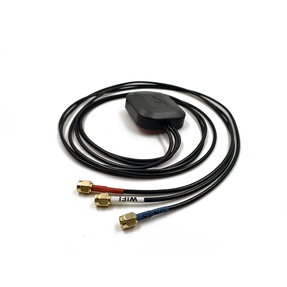
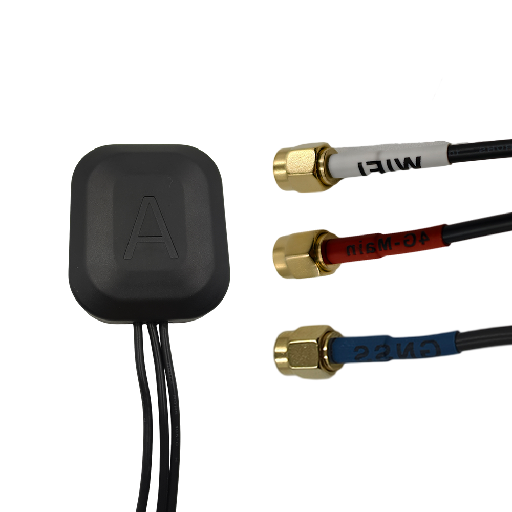
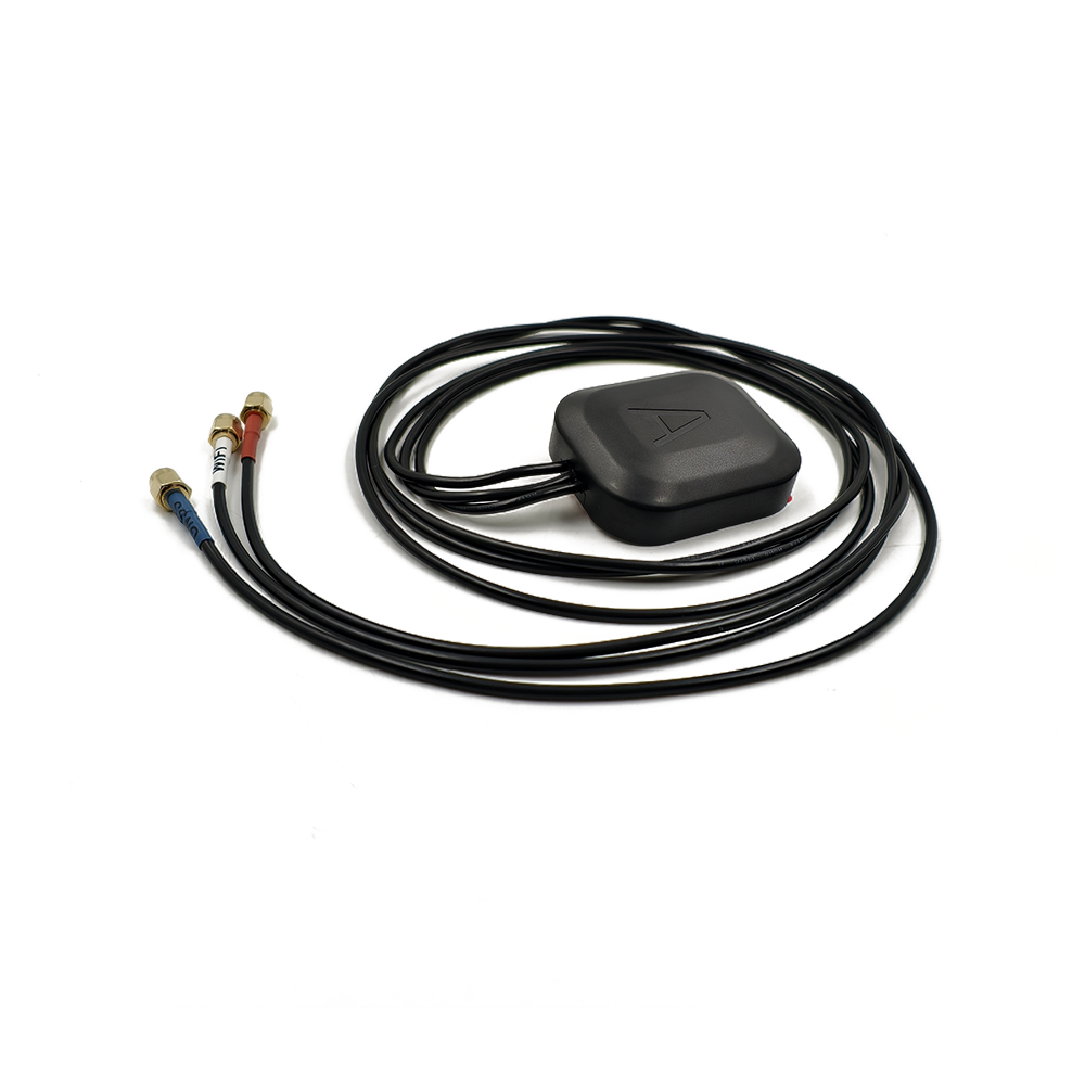
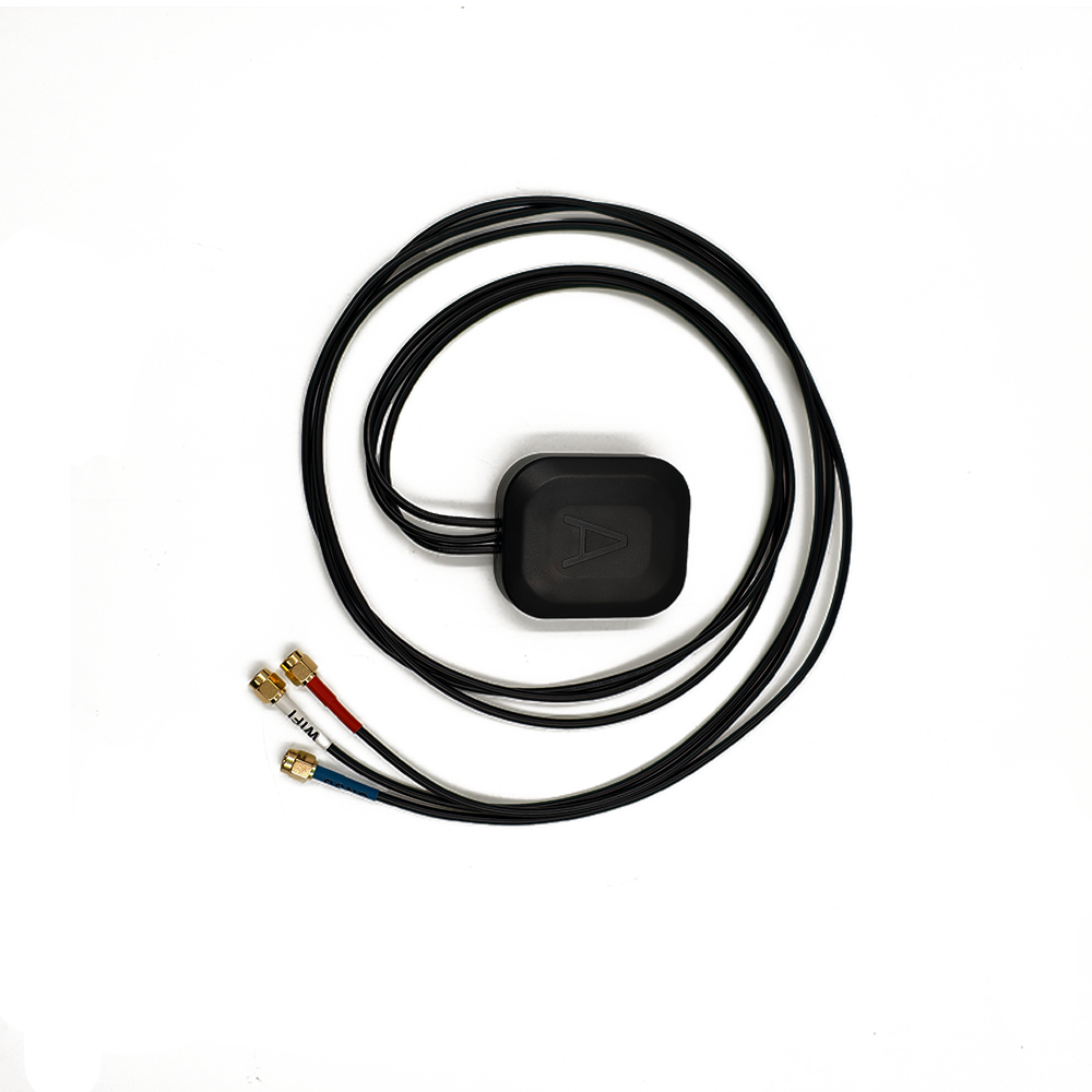
An L1/L2/L5 multi-band RTK ceramic antenna is a specialized type of passive patch antenna designed to receive three critical frequency bands utilized by GNSS constellations: the legacy L1 band (centered around 1575.42 MHz), the L2 band (1227.60 MHz), and the modernized L5 band (1176.45 MHz). The "RTK" designation signifies that its primary purpose is to support centimeter-level positioning by providing the high-fidelity carrier-phase measurements required by the RTK algorithm. The use of a "ceramic" substrate with a high dielectric constant is the enabling technology that allows this advanced functionality to be packaged into a compact, surface-mount form factor, making it suitable for integration into a wide range of equipment, from survey rovers and drones to agricultural machinery and autonomous vehicles.
The driving imperative behind the development of this multi-band technology is the limitation of single-band (L1-only) and even dual-band (L1/L2) systems. While L1/L2 RTK is highly capable, the introduction of the L5 band (and its equivalents: Galileo E5a and BeiDou B2a) offers a paradigm shift in performance. Each band carries unique information and possesses distinct characteristics. The L1 band is the workhorse, available on all satellites. The L2 band, often used for military purposes but now available with open codes, provides a second frequency that is crucial for ionospheric delay calculation. The L5 band, however, is a civil signal designed from the ground up for "safety-of-life" applications. It features a higher power, a wider bandwidth, and an advanced modulation scheme that makes it more robust against interference, multipath, and signal degradation.
The primary role of this triple-band antenna is to act as a superior data collection point for the RTK engine. By simultaneously receiving signals on L1, L2, and L5, it provides the receiver with a rich and diverse dataset. This allows the RTK algorithm to perform several critical functions with far greater speed and confidence:
Ionospheric Error Mitigation: The ionosphere delays GNSS signals by an amount inversely proportional to the square of the frequency. By comparing the measured phase delays on three different frequencies (L1, L2, L5), the receiver can model and eliminate this major source of error with much higher precision than is possible with just two frequencies.
Faster and More Robust Integer Ambiguity Resolution: The additional, cleaner measurements from the L5 band provide more equations for the complex mathematical process of resolving the integer number of carrier waves between the satellite and receiver. This results in a significantly reduced "time-to-first-fix" (TTFF) and a much lower probability of an incorrect fix or a loss of fix in challenging signal environments.
Enhanced Multipath Resistance: The wider bandwidth of the L5 signal inherently provides better resistance to multipath—the phenomenon where a signal arrives at the antenna via a reflected path, causing positioning errors. The antenna's design further suppresses multipath through its radiation pattern and phase center stability.
In essence, the L1/L2/L5 multi-band RTK ceramic antenna is a gateway to next-generation precision. It moves beyond simply receiving more signals to receiving better signals and leveraging the synergistic relationships between them. It is the hardware foundation that allows advanced algorithms to perform at their best, ensuring that centimeter-level accuracy is not just achievable but is consistently reliable, rapid, and resilient in the face of the real-world errors that have traditionally plagued high-precision GNSS.
The design and construction of an L1/L2/L5 multi-band RTK ceramic antenna is a feat of electromagnetic engineering that balances the conflicting demands of multi-frequency operation, extreme phase stability, and compact miniaturization. It is a multi-layered, precision instrument where every material, dimension, and geometric feature is meticulously optimized to achieve unparalleled performance across three distinct frequency bands.
1. The Ceramic Substrate: The Foundation for Miniaturization
The core of the antenna is a block of specialized ceramic material, which is the key to its small size. This is not a generic ceramic but a proprietary formulation engineered for specific RF properties:
High Dielectric Constant (εr): Typically ranging from 20 to 40, the high εr reduces the wavelength within the material (λ_d = λ_0 / √εr). This allows the physical dimensions of the radiating patches to be a fraction of the free-space wavelength, enabling a multi-band antenna to fit into a compact footprint, often as small as 25x25mm.
Low Loss Tangent (tan δ): The material must have extremely low electromagnetic loss (tan δ < 0.002) to ensure high radiation efficiency. Any energy dissipated as heat within the ceramic is energy not radiated, directly reducing the antenna's gain and performance.
Temperature Stability: The dielectric constant must remain stable over a wide operating temperature range (e.g., -40°C to +85°C). Thermal drift would shift the resonant frequencies and, more critically, alter the antenna's phase center, introducing unacceptable errors into the RTK solution.
2. The Radiating Element: The Stacked Patch Architecture
The most common and effective design for a triple-band antenna is the stacked patch or multi-layer patch configuration. This involves multiple radiating elements vertically stacked and electromagnetically coupled.
Top Layer (L5 Band Patch): The uppermost parasitic patch is typically the largest and is tuned to resonate at the lowest frequency band, L5 (1176.45 MHz). As a parasitic element, it is not directly fed but is excited by electromagnetic coupling from the layer beneath.
Middle Layer (L2 Band Patch): A smaller patch is located below the L5 patch and is tuned to the L2 band (1227.60 MHz). In some designs, this layer may also be a parasitic element.
Bottom Layer (L1 Band Patch): The primary driven patch is on the lowest layer and is tuned to the highest frequency, L1 (1575.42 MHz). This patch is directly connected to the antenna's feed point.
This stacked approach allows for independent optimization of the performance for each band. The coupling between the layers is carefully modeled to ensure efficient operation across all three frequencies without undesirable interaction that could detune the antenna or degrade its radiation pattern.
3. Achieving Circular Polarization and Phase Center Stability
GNSS signals are Right-Hand Circularly Polarized (RHCP). A single feed point would create linear polarization. To achieve CP, the antenna's geometry must be perturbed to excite two orthogonal modes with a 90-degree phase difference. This is often accomplished through techniques like:
Dual Feed with Hybrid Coupler: A high-performance method where the patch is fed at two points via a 90-degree hybrid coupler circuit. This ensures perfect amplitude and phase balance, resulting in a very pure circular polarization and a low, stable Axial Ratio across all three bands. This method is complex but offers the best phase center stability.
Single Feed with Perturbations: For cost-sensitive designs, a single feed with strategically placed slots or notches can be used, though this can compromise phase stability and axial ratio performance compared to the dual-feed approach.
Phase Center Stability is the single most critical characteristic of an RTK antenna. The antenna's design—its symmetry, layer alignment, and feed mechanism—is laser-focused on minimizing Phase Center Variation (PCV), the movement of the electrical phase center with satellite elevation and azimuth. A stable phase center ensures that measurement errors are not introduced by the antenna itself.
4. The Ground Plane
A solid, continuous ground plane is located beneath the ceramic stack. It serves to direct the radiation pattern upward, provide a stable electrical reference, and is instrumental in achieving a low axial ratio and consistent performance. The size of the ground plane, both on the antenna itself and on the host PCB, influences the antenna's gain and pattern.
5. Integration and Calibration
The entire assembly is housed in a protective enclosure with an RF-transparent lid. However, the antenna's performance is co-designed with the host printed circuit board (PCB). A strict keep-out area free of ground and components must be maintained directly beneath the antenna to prevent detuning.
Finally, each antenna design undergoes rigorous calibration in an anechoic chamber. Its precise Phase Center Variation (PCV) is measured for all three bands (L1, L2, L5) and for all angles of arrival. This PCV data is provided to the user and applied within the RTK processing software, mathematically correcting for the antenna's inherent imperfections and enabling the highest possible accuracy.
The construction of an L1/L2/L5 antenna is thus a complex interplay of advanced materials, multi-physics electromagnetic simulation, and precision manufacturing, all aimed at creating a single, compact component that delivers three perfectly tuned and stable windows to the GNSS constellations.
The operation of an L1/L2/L5 multi-band RTK ceramic antenna is a sophisticated process of selective resonance, signal purification, and data enrichment. Its working principles are dedicated to capturing the carrier phase of GNSS signals across three frequencies with such purity and stability that the downstream RTK engine is empowered to perform at the absolute limits of its capability, achieving rapid, reliable, and resilient centimeter-level positioning.
Fundamental Resonance and Multi-Band Operation
At its core, each layer of the stacked patch antenna functions as a resonant cavity. The dimensions of the L1, L2, and L5 patches are precisely calculated to be electrically half-wavelength long within the high-dielectric ceramic material at their respective frequencies. When the electromagnetic energy from a satellite signal matches one of these frequencies, it excites a strong standing wave on the corresponding patch. The stacked configuration is carefully designed so that these resonances are distinct yet efficiently coupled. The L1-driven patch excites the L2 parasitic patch, which in turn excites the L5 parasitic patch, allowing a single feed point to efficiently transfer energy across all three bands. This design ensures that the antenna presents a well-matched impedance (close to 50 ohms) at each of the three target frequencies, maximizing power transfer from the antenna to the receiver.
The Crucial Role of Triple-Frequency Data in RTK
The antenna's primary function is to provide the raw, high-quality phase measurements for the RTK algorithm. The availability of three frequencies transforms this process:
Advanced Ionospheric Delay Estimation: The ionosphere is a dispersive medium, meaning it delays signals based on their frequency. The delay is proportional to 1/f². A dual-frequency (L1/L2) system can calculate and remove about 99% of the ionospheric error. However, the residual error, especially during periods of high ionospheric activity, can still be significant enough to delay or disrupt the integer ambiguity resolution. Adding a third frequency (L5) provides a redundant and independent measurement of the same delay. This allows the receiver to model the ionosphere with even greater precision, effectively eliminating this error source and leading to a more stable and reliable RTK solution, particularly over long baselines.
Ultra-Fast Integer Ambiguity Resolution: Resolving the integer ambiguity—the unknown whole number of carrier wavelengths between the satellite and receiver—is the key to RTK. The three frequencies create additional, longer "virtual" wavelengths through linear combinations of the fundamental signals (e.g., the wide-lane and extra-wide-lane combinations). These virtual signals have wavelengths that can be several meters long, making the integer ambiguity much easier to resolve quickly and correctly. Once the integer for these wide-lane signals is found, it constrains the solution for the narrower L1 and L5 ambiguities, dramatically reducing the time-to-first-fix from minutes to often less than 10 seconds, even from a cold start.
Multipath Mitigation and Signal Reliability: The L5 signal is inherently more robust against multipath due to its wider bandwidth (10 MHz for L5 vs. 2 MHz for the C/A code on L1) and its advanced modulation (BOC). A wider bandwidth allows the receiver's correlators to better distinguish between the direct line-of-sight signal and a delayed reflected version. The antenna itself contributes to multipath rejection through its radiation pattern, which is designed to have high gain towards the zenith and low gain at the horizon where reflected signals typically originate. The triple-frequency capability provides redundancy; if the L1 signal from a satellite is corrupted by multipath, the receiver can potentially rely on the cleaner L5 signal from the same satellite to maintain the lock.
The Signal Path and Phase Stability
The antenna's working principle is centered on phase stability. The phase of the carrier wave must be measured with millimeter precision. Any movement of the antenna's electrical phase center—the point from which the signal appears to emanate—as a satellite moves across the sky would be interpreted by the receiver as a positioning error. The symmetric stacked-patch design, stable ceramic material, and precise feed mechanism are all engineered to minimize this Phase Center Variation (PCV). The provided PCV calibration data allows the receiver's software to correct for the tiny remaining variations, effectively creating a perfectly stable virtual phase center for each frequency.
In summary, the L1/L2/L5 antenna works by acting as a highly selective, ultra-stable, triple-frequency transducer. It doesn't just receive more signals; it provides a qualitatively superior dataset that enables the RTK engine to overcome its traditional limitations. It turns the complex challenges of ionospheric delay, integer ambiguity, and multipath from potential show-stoppers into manageable problems, ensuring that centimeter accuracy is not a best-case scenario but a consistent, reliable reality.
The adoption of L1/L2/L5 multi-band RTK technology represents a significant leap forward in high-precision positioning. However, this advanced capability comes with a distinct set of trade-offs that must be understood to fully appreciate its value proposition and implementation requirements.
Advantages
Unmatched Performance in Integer Ambiguity Resolution: The primary advantage is the dramatic improvement in the speed and reliability of fixing the integer ambiguities. The third frequency (L5) creates extra-wide-lane signals that have wavelengths of several meters. Resolving the integer on these long wavelengths is fast and virtually foolproof. This leads to phenomenally quick time-to-first-fix,
often achievable in under 10 seconds even without prior information, compared to potentially minutes for a dual-frequency system. This maximizes productivity in the field.
Superior Resilience to Ionospheric Interference: The atmosphere, particularly the ionosphere, is the largest source of error in GNSS. During periods of high solar activity, dual-frequency (L1/L2) RTK can struggle with solution volatility and extended convergence times over longer baselines (>10 km). The third frequency provides a critical independent measurement, allowing for a more robust and precise estimation of the ionospheric delay. This results in significantly improved stability and reliability of the RTK fix, reducing the risk of the solution dropping back to a float state during periods of atmospheric disturbance.
Enhanced Robustness and Signal Redundancy: The L5 band is a modern signal designed with higher power, wider bandwidth, and advanced modulation. This makes it more resistant to multipath and radio frequency interference (RFI). In challenging environments like urban canyons or under light tree cover, if the L1 signal from a satellite is degraded, the receiver can often still utilize the stronger, cleaner L5 signal from the same satellite. This triple-frequency redundancy ensures that more satellites remain "usable," maintaining a high position solution integrity even when the signal environment is less than ideal.
Future-Proofing and Support for All Constellations: All modernizing GNSS constellations (GPS, Galileo, BeiDou, QZSS) are broadcasting open signals on the L1, L2, and L5/E5a/B2a bands. Investing in a triple-band antenna ensures compatibility with all current and future satellites. This maximizes the number of available satellites in view, which improves geometry (lower DOP values) and further enhances accuracy and reliability. It protects the investment against obsolescence as the satellite constellations continue to evolve.
High Performance in a Compact Form Factor: The use of high-dielectric ceramic substrate allows this advanced triple-band functionality to be packaged into a small, surface-mount component. This enables integration into space-constrained applications like drones, robotics, and handheld mapping devices without sacrificing performance, a feat that would be impossible with older antenna technologies.
Challenges and Limitations
Higher Cost and Complexity: The primary challenge is cost. The stacked ceramic design is materially more complex to manufacture than a single-layer patch. The need for precise alignment of multiple layers, the sophisticated feed network (especially if a dual-feed system is used), and the rigorous calibration process all contribute to a significantly higher unit cost compared to L1-only or even L1/L2 antennas.
Design and Integration Sensitivity: While the ceramic allows for a small footprint, the antenna's performance remains highly dependent on proper integration. The mandatory keep-out area on the host PCB must be strictly adhered to, as nearby components or ground pours will detune the carefully balanced multi-frequency response. The design of the matching network also becomes more complex to ensure optimal performance across all three bands simultaneously.
Power Consumption (for Active Variants): While the antenna itself is passive, most are implemented as active antennas with an integrated Low-Noise Amplifier (LNA) to overcome cable loss. A high-quality LNA for three bands may have marginally higher power consumption than a simpler single-band LNA, though this is usually a minor consideration in the overall system power budget.
Computational Load: The benefits of triple-frequency data come at the cost of increased computational demand on the GNSS receiver. The receiver must run more complex algorithms to process the additional measurements and compute the various linear combinations of frequencies. This requires a more powerful processor, which can influence the cost and power consumption of the receiver itself.
Calibration Complexity: Characterizing the Phase Center Variation (PCV) for an L1/L2/L5 antenna is more complex than for a single-band model. The PCV must be accurately measured and defined for each frequency band. Users must ensure that their processing software supports and correctly applies the specific calibration data for their antenna model across all three bands to realize the full accuracy potential.
In conclusion, the advantages of the L1/L2/L5 multi-band antenna are overwhelmingly focused on achieving a new level of performance: breathtakingly fast initialization, rock-solid reliability in the face of atmospheric and RF challenges, and future-proof capability. The challenges are primarily economic and related to integration complexity. For applications where uptime, reliability, and maximum productivity are critical—such as professional surveying, precision agriculture, and autonomous systems—the higher initial investment is rapidly justified by the operational benefits gained.
The L1/L2/L5 multi-band RTK ceramic antenna is a transformative technology that is unlocking new possibilities and elevating performance across a wide spectrum of high-precision industries. Its unique capabilities are being leveraged in applications where its advantages directly translate into tangible benefits in efficiency, safety, and capability. Furthermore, its development is driving and being driven by several key future trends in the world of positioning.
Applications
Precision Agriculture and Autonomous Farming: This is one of the largest and most demanding applications. For automated tractors, sprayers, and harvesters, a quick and reliable RTK fix is paramount.
Fast Initialization: A tractor entering a field can achieve a centimeter-accurate fix in seconds, maximizing productive time.
Uninterrupted Operation: The resilience to ionospheric disturbances and multipath ensures the auto-guidance system does not disengage on long passes or under challenging conditions, preventing skipped rows or overlapping applications which waste inputs and reduce yield.
Support for Advanced Practices: It enables high-speed, high-precision applications like variable rate seeding and fertilizing, where the implement is moving quickly and cannot afford any positioning uncertainty.
Professional Surveying, Mapping, and GIS: Surveyors and mapping professionals require the utmost reliability and accuracy.
Productivity in Difficult Environments: The ability to maintain a fix under tree canopy, near buildings, or in urban canyons is greatly enhanced by the redundant L5 signals, reducing the number of required re-initializations.
Long Baseline RTK: The improved ionospheric modeling makes network RTK and single-base RTK more reliable over longer distances, increasing the working range from a base station or correction network.
Autonomous Navigation and Robotics: For drones, ground robots, and autonomous vehicles, safety and reliability are non-negotiable.
Drones for Mapping & LiDAR: Provides the precise positioning and, crucially, the precise orientation (PPK/RTK) needed for accurate aerial mapping and LiDAR point cloud generation without the need for numerous ground control points.
Autonomous Mobile Robots (AMRs): In warehouses, ports, and mines, AMRs use RTK for absolute positioning outdoors, fusing it with LiDAR and other sensors for navigation. The multi-band antenna's quick re-acquisition after passing through a building is critical.
Driver-Assistance and Autonomy: Serves as a high-integrity source of absolute position for automotive testing and developing autonomous vehicle systems.
Construction and Machine Control: Bulldozers, graders, and excavators use GNSS for machine control.
Uptime: The robustness of the triple-frequency signal ensures continuous operation, preventing costly downtime on the construction site.
Accuracy in Dynamic Environments: The stability of the solution is critical for the blade of a grader to maintain its design grade without error.
Scientific and Monitoring Applications: Used for high-precision monitoring of tectonic plate movements, volcanic deformation, and landslide creep. The stability and long-baseline performance are essential for detecting movements of a few millimeters per year.
Future Trends
Tightly Coupled Multi-Band + Inertial Navigation Systems (INS): The future lies in deeply integrated systems. The L1/L2/L5 antenna will be co-packaged with a high-grade IMU into a single, optimized "GNSS/INS" module. The triple-frequency GNSS provides the absolute position anchor, while the IMU provides high-rate velocity and attitude data. The deeply fused solution offers continuous, smooth, and accurate positioning even during short GNOS outages (e.g., in tunnels or under dense cover), which is critical for autonomy.
The Rise of PPP-RTK and Advanced Correction Services: Triple-frequency data is a key enabler for Precise Point Positioning with Real-Time Kinematic corrections (PPP-RTK). This technique aims to deliver near-RTK accuracy globally using precise satellite orbit and clock corrections, without the need for a local base station. The third frequency accelerates the PPP convergence time from tens of minutes to just a few minutes, making it a practical technology for many applications.
Miniaturization and Integration into Consumer Devices: As manufacturing costs decrease, we will begin to see L1/L2/L5 antennas trickle down into high-end consumer devices. Future smartphones, action cameras, and augmented reality glasses could leverage this technology for centimeter-accurate positioning, enabling new location-based services and experiences.
Focus on Anti-Jamming and Anti-Spoofing (AJ/AS): As society becomes more dependent on GNSS, the threat of jamming and spoofing grows. Future multi-band antennas will incorporate built-in filtering and may evolve into Controlled Reception Pattern Antennas (CRPAs) that can actively nullify interference sources, protecting the integrity of the positioning solution.
Standardization for Autonomous Systems: The automotive and robotics industries will drive standards for high-performance GNSS antennas. The L1/L2/L5 ceramic patch, with its proven performance and compact form factor, is poised to become a benchmark form factor for these standards, especially for applications where a low-profile antenna is required.
The L1/L2/L5 multi-band RTK ceramic antenna is not the end of the road but a significant milestone. Its future is one of deeper integration, greater intelligence, and wider adoption, solidifying its role as the cornerstone of the next generation of high-precision location-aware systems.
Conclusion
The L1/L2/L5 multi-band RTK ceramic antenna represents a definitive leap in the evolution of high-precision global navigation technology. It is far more than an incremental upgrade; it is a fundamental architectural advancement that effectively solves some of the most persistent and challenging problems that have plagued RTK positioning since its inception. By harnessing the power of three distinct frequency bands, this antenna transitions high-precision GNSS from a technology that often required ideal conditions and patience to one that delivers instantaneous, robust, and unwavering centimeter-level accuracy in the real world.
Its design is a masterpiece of electromagnetic engineering, leveraging a stacked ceramic architecture to achieve what was once thought impossible: packing the performance of a survey-grade antenna into a compact, ruggedized form factor suitable for integration into mobile and autonomous platforms. The meticulous focus on phase center stability, achieved through symmetric design and precise calibration, ensures that the antenna itself introduces minimal error, providing the RTK engine with the pristine raw data it requires to perform at its theoretical best.
The advantages it delivers are transformative. The near-instantaneous time-to-first-fix obliterates downtime, maximizing productivity for surveyors and farmers alike. The robust resistance to ionospheric disturbance and multipath instills a new level of confidence, allowing equipment to operate continuously and accurately through atmospheric events and in challenging signal environments. The inherent redundancy and future-proofing offered by triple-frequency reception ensure that systems built today will continue to improve as new satellites are launched and new signals become available.
While the path to this performance is not without its challenges—primarily the higher cost and integration complexity—these are not arbitrary drawbacks but rather the justified price of a superior technological solution. The return on investment is measured in saved time, eliminated waste, enhanced safety, and unlocked capabilities that were previously unattainable.
Looking forward, the L1/L2/L5 antenna is not the final destination but the new foundation. It is the essential sensor that will underpin the autonomous revolution, providing the critical absolute positioning layer upon which the safety of driverless cars and the efficiency of robotic fleets will depend. Its evolution will be towards tighter integration with other sensors, greater intelligence, and enhanced security features.
In conclusion, the L1/L2/L5 multi-band RTK ceramic antenna is a testament to the power of innovation focused on a clear goal: the complete and total mastery of precision positioning. It has successfully addressed the traditional vulnerabilities of RTK, turning its former limitations into strengths. By providing a faster, smarter, and more resilient window to the satellites, it has firmly established itself as the gold standard and indispensable tool for anyone for whom "close enough" is not an option. It is the key that has unlocked the full potential of modern GNSS, paving the way for a future where precise location is a ubiquitous and utterly reliable utility.

 86 0755 2819 9597
Lucy Yang | lucy.y@toxutech.com
Nicole Li | nicole@toxutech.com
Dotty Zhao | sales04@toxutech.com
Global Business Director / Sales Team / Global Operations


 En
En Cn
Cn Korean
 Home >


