

-
Products -PCBA Manufacturing RF Connectors RF Cable Assemblys Embedded Antennas External Antennas Positioning Chips and Modules
RF Connectors

RF Cable Assemblys
Embedded Antennas
External Antennas
Positioning Chips and Modules


 Language


Language


The Global Navigation Satellite System (GNSS) has become an indispensable technology, seamlessly integrated into the fabric of modern life. From navigating city streets with a smartphone to precision agriculture, scientific research, and global logistics, the ability to pinpoint one's location anywhere on Earth is a technological marvel. At the heart of every GNSS receiver lies its most critical and sensitive component: the antenna. Among the various antenna types, the integrated ceramic patch antenna has emerged as the dominant form factor for a vast array of consumer, commercial, and industrial applications. This overview delves into the fundamental nature, significance, and evolutionary context of this pivotal technology.
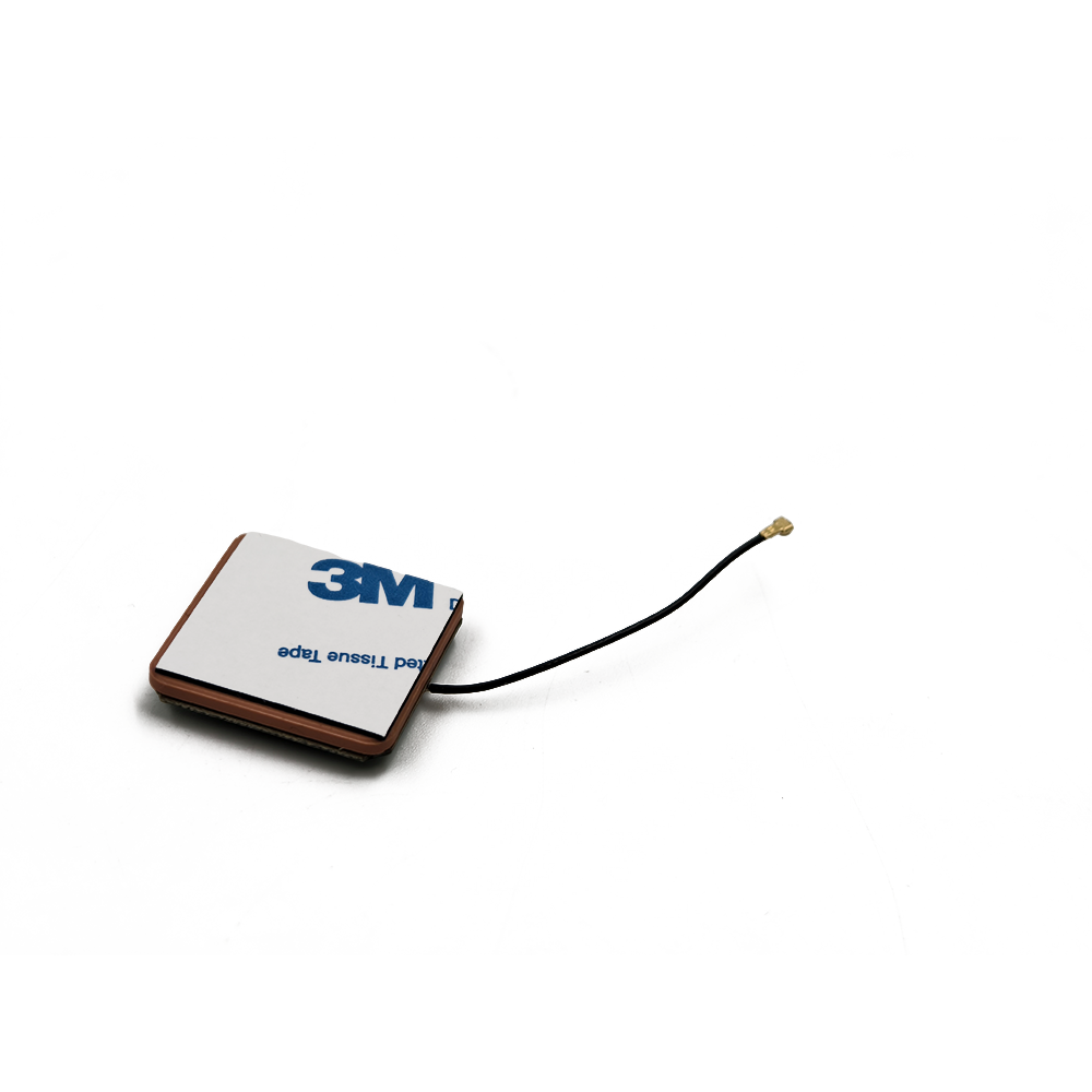
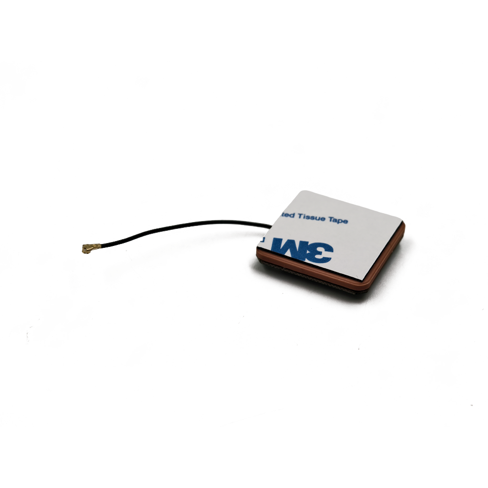
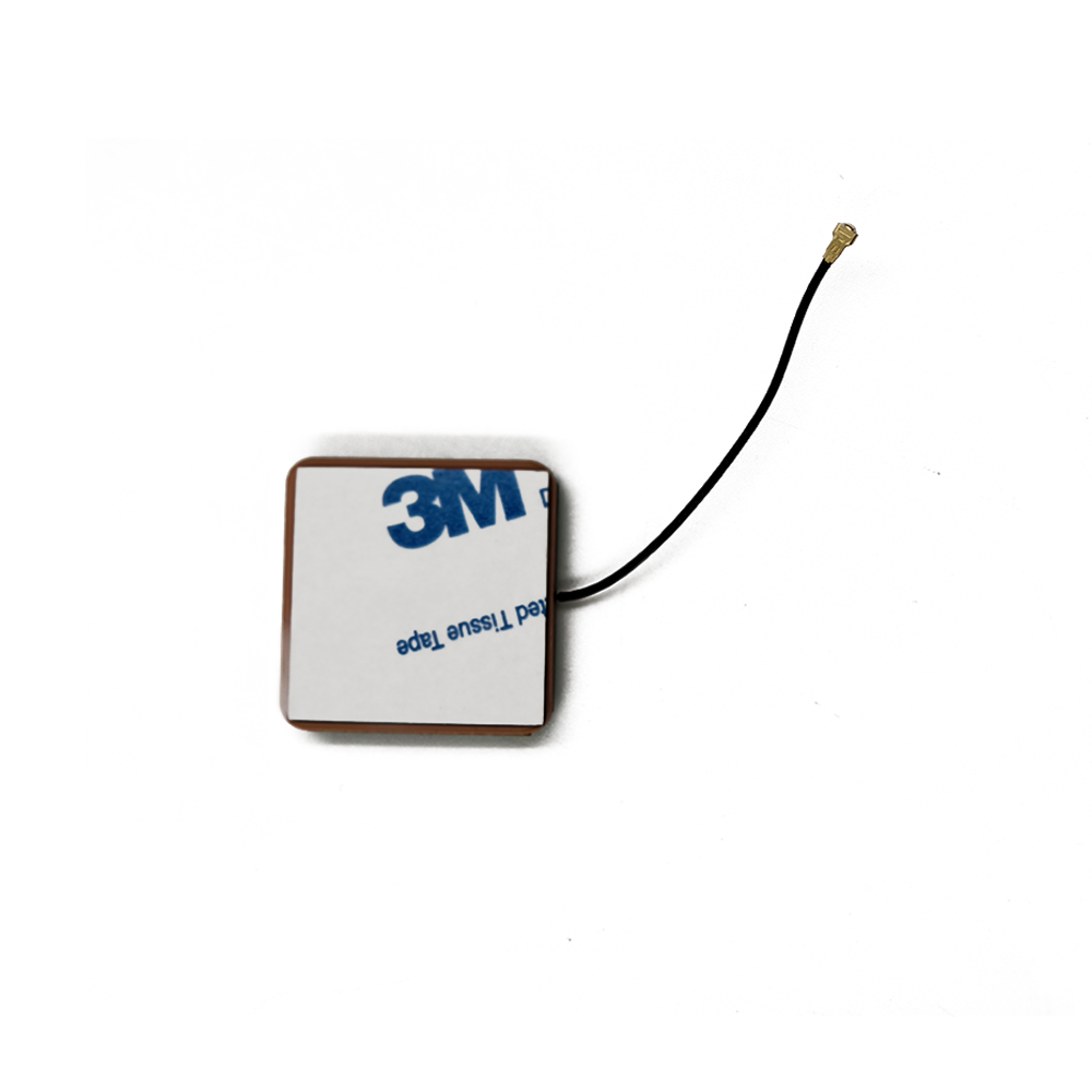
An integrated GNSS ceramic patch antenna is a type of passive radio antenna designed specifically to receive the circularly polarized signals broadcast by satellite constellations such as GPS (USA), GLONASS (Russia), Galileo (EU), and BeiDou (China). The term "integrated" signifies that it is not merely a standalone radiator but a complete antenna system. It typically incorporates the ceramic radiating element, a ground plane, a low-noise amplifier (LNA), often bandpass filters, and sometimes even a saw filter, all housed within a single, compact, and shielded package. This integration is crucial as it transforms a simple patch of metal into a robust, performance-optimized subsystem ready for embedding into a host device.
The "ceramic" component refers to the substrate material upon which the antenna element is fabricated. Unlike traditional antennas that might use FR4 (fiberglass) or other plastics, these antennas utilize specialized ceramic compounds, often a blend of alumina or other proprietary ceramic materials. The choice of ceramic is deliberate and driven by its critical electromagnetic properties, primarily its dielectric constant (εr). Ceramics can have a very high dielectric constant (e.g., 20-40 and even higher), which allows for a significant physical size reduction of the antenna. The wavelength of an electromagnetic wave within a material is inversely proportional to the square root of its dielectric constant. A high εr shrinks the effective wavelength, enabling the antenna to be resonant at GNSS frequencies (around 1.575 GHz for L1 band) while maintaining a very small form factor, often a square measuring just 10mm to 25mm per side.
The evolution of the ceramic patch antenna is a story of the relentless pursuit of miniaturization, performance, and cost-effectiveness. Early GNSS systems, primarily for military and high-end commercial use, often employed larger helical or quadrifilar helix antennas. While performant, these were bulky and expensive. The advent of the patch antenna, initially used in aerospace and satellite communications, offered a low-profile, planar alternative. The integration of this technology with high-dielectric ceramics in the 1990s and 2000s was the breakthrough that enabled its proliferation into mass-market devices like personal navigation devices (PNDs) and, most significantly, smartphones.
Today, the sight of a small, silver, square component on a circuit board, often labeled "GPS" or "GNSS," is ubiquitous. This is the integrated ceramic patch antenna. Its success is attributed to its perfect alignment with the needs of modern electronics: it is small, lightweight, low-cost when mass-produced, mechanically robust due to its solid construction, and can be easily surface-mounted (SMT) onto a printed circuit board (PCB) using automated assembly processes. Furthermore, its integrated LNA ensures that the extremely weak signals from satellites—which have traveled over 20,000 km and can be as low as -130 dBm—are amplified before being sent down a lossy transmission line (like a coaxial cable) to the GNSS receiver chip, preserving the signal-to-noise ratio (SNR) that is paramount for accurate positioning.
In summary, the integrated GNSS ceramic patch antenna is a masterpiece of electronic miniaturization and integration. It is the unsung hero that translates faint whispers from orbiting satellites into a strong, usable signal, enabling the location-aware world we live in. Its development mirrors the broader trends in electronics: integration, miniaturization, and the clever use of material science to overcome fundamental physical constraints. From its humble beginnings, it has become the de facto standard, empowering everything from wearable fitness trackers to autonomous vehicles.
The design and construction of an integrated GNSS ceramic patch antenna is a sophisticated process that blends electromagnetics, material science, and RF engineering. It is far more than a simple piece of ceramic with metal on it; it is a carefully engineered system where every layer and material choice profoundly impacts performance. Understanding its architecture is key to appreciating its functionality.
The construction is typically a multi-layered stack-up, often encapsulated in a protective plastic housing or a metal shield can.
1. The Ceramic Substrate Core:
This is the foundational layer and the heart of the antenna. It is a flat, square, or rectangular block of ceramic material. The primary characteristic of this ceramic is its very high dielectric constant (εr), as mentioned, which enables miniaturization. However, other properties are equally critical:
Loss Tangent (tan δ): This measures the rate at which RF energy is absorbed and converted into heat by the dielectric material. A low loss tangent is absolutely essential for antenna efficiency. High losses would absorb the precious satellite signal before it could be radiated or received, rendering the antenna useless. Ceramic formulations are carefully optimized for a high εr and a very low tan δ.
Temperature Stability: The dielectric constant must remain stable over a wide operating temperature range (e.g., -40°C to +85°C). If εr drifts with temperature, the antenna's resonant frequency will shift, potentially detuning it away from the GNSS band and degrading performance.
2. The Radiating Patch Element:
On the top surface of the ceramic substrate, a silver or other highly conductive metallic ink is printed, sintered, or plated to form the radiating element. This is the "patch" itself. Its precise dimensions (length and width) determine the resonant frequency. The patch is typically square, as it naturally supports two orthogonal resonant modes, which is the foundation for generating circular polarization.
3. The Ground Plane:
The bottom surface of the ceramic block is almost entirely coated with a metal layer, forming the ground plane. This is a critical component of patch antenna design. The radiating patch, the dielectric substrate, and the ground plane together form a resonant cavity. The ground plane reflects energy, confines the fields, and directs the antenna's radiation pattern predominantly forward (away from the ground plane). Its size also influences the antenna's performance characteristics, including its bandwidth and pattern.
4. The Feed Mechanism:
Energy must be transferred to and from the radiating patch. This is done via a feed. The most common method for these antennas is an indirect feed, such as:
Aperture-Coupled Feed: A more advanced technique where the patch is fed electromagnetically through a slot in the ground plane. A microstrip feedline on a separate layer below the ground plane couples energy through this slot to excite the patch. This allows for better impedance matching and isolation between the feed network and the radiator.
Probe Feed: A simpler method where a pin (probe) is connected directly through the substrate from the ground plane to the patch. While effective, it can be more mechanically complex.
5. The Low-Noise Amplifier (LNA):
This active component is what makes the antenna "integrated." The LNA is a semiconductor amplifier placed electrically as close to the radiating element as possible. Its primary purpose is to amplify the extremely weak GNSS signals (often drowned in noise) by a significant factor, typically 15 to 28 dB. Crucially, it must do this while adding as little self-generated electronic noise as possible, quantified by its Noise Figure (NF). A low NF (e.g., <1.5 dB) is a key specification. The LNA requires power, which is supplied to the antenna module via a separate voltage input and is often delivered up the same coaxial cable that carries the signal out (using a Bias-T circuit at the receiver end).
6. Supporting Components and Filtering:
The RF pathway often includes surface-mounted components like:
Bandpass Filters: These are placed before or after the LNA to reject out-of-band interference. GNSS signals are incredibly weak and can be easily jammed by strong nearby transmitters like cellular (4G/5G), WiFi, or Bluetooth radios. A filter ensures only frequencies around 1.575 GHz are amplified.
SAW (Surface Acoustic Wave) Filters: These are extremely sharp, high-performance filters sometimes integrated for superior rejection of very close-in interference.
7. Shielding and Packaging:
The entire assembly—ceramic element, LNA, and filters—is typically housed within a protective package. This often consists of a metal shield can that solders to the host PCB, creating a Faraday cage that protects the sensitive RF electronics from external electromagnetic interference (EMI). The top of the package is usually plastic or a non-conductive material to allow the RF signals to pass through unimpeded.
The design process involves extensive electromagnetic simulation using software like CST or HFSS. Engineers simulate the patch dimensions, feed location, and ground plane size to optimize for key parameters: resonant frequency, impedance matching (to 50 ohms), bandwidth (must cover all desired GNSS bands, e.g., L1, L2, L5), axial ratio (for circular polarization purity), and radiation pattern. The integration of the LNA and filters requires additional circuit simulation to ensure stability, gain, and linearity. The final product is a marvel of integration, packing a complete, high-performance RF front-end into a package often smaller than a postage stamp.
The operation of an integrated GNSS ceramic patch antenna is governed by the fundamental principles of patch antenna theory, amplified by the active electronics within its package. Its primary job is to efficiently convert the electromagnetic energy from satellite signals into a guided electrical signal that can be processed by a receiver, all while rejecting noise and interference.
Fundamental Radiation Mechanism:
A patch antenna operates as a resonant cavity. The top metal patch, the bottom ground plane, and the dielectric substrate between them form this cavity. The dimensions of the patch, specifically its length (L), are designed to be approximately half of the effective wavelength within the dielectric material at the target frequency. Due to the high εr of the ceramic, this effective wavelength is greatly reduced, allowing for a physically small L.
When the patch is excited by its feed (e.g., via a probe or aperture), electromagnetic fields are set up within the cavity. The dominant mode of operation is the TM₁₀ mode. In this mode, the electric field (E-field) is oriented perpendicular to the patch's surface, with its magnitude varying sinusoidally across the length of the patch. It is maximum at the center and zero at the edges (radiating slots). The radiation occurs primarily from the fringing fields that extend beyond the edges of the patch into the surrounding space. These fringing fields are what launch the radio wave into the atmosphere or receive it.
Achieving Circular Polarization (CP):
GNSS satellites transmit right-hand circularly polarized (RHCP) signals. To efficiently receive these signals, the antenna must also be RHCP. A linear antenna would suffer a 3 dB loss in signal strength when receiving a CP wave. Circular polarization is achieved in a patch antenna by perturbing the fundamental resonant structure to excite two orthogonal modes with equal amplitude but with a 90-degree phase difference between them.
The most common method is to introduce a physical asymmetry in the patch. A classic technique is to truncate two opposite corners of the square patch or to insert narrow slits at specific locations. This asymmetry creates two degenerate orthogonal modes (e.g., along the x and y-axis) that resonate at slightly different frequencies. When the antenna is fed at a single point, it excites both modes. By carefully designing the perturbation, the antenna is tuned so that at the center frequency (1.575 GHz), the phase difference between these two modes is exactly 90 degrees, and their amplitudes are equal. The superposition of these two orthogonal linear waves, 90 degrees out of phase, results in a wave that rotates in a circular manner—hence, circular polarization. The quality of this CP is measured by the Axial Ratio (AR); a perfect CP wave has an AR of 0 dB (a ratio of 1:1), and practical antennas strive for a low AR (e.g., <3 dB) over a wide angular range.
Signal Reception and Amplification Chain:
Capture: An RHCP electromagnetic wave from a satellite arrives at the antenna.
Conversion: The ceramic patch element resonates, and the fringing fields induce a small oscillating current on the patch. This current is coupled through the feed mechanism to the antenna's output port. The voltage at this port is an extremely weak electrical analog of the satellite signal, typically around -130 dBm.
Filtering (Initial): This tiny signal may first pass through a bandpass filter to block strong out-of-band signals from cellular radios or other sources that could overload the subsequent amplifier.
Amplification: The signal then enters the Low-Noise Amplifier (LNA). The LNA's sole purpose is to add gain (e.g., +26 dB) to this signal while contributing the absolute minimum amount of its own noise. This is critical because amplifying the signal along with the noise it has already picked up is manageable, but adding significant new noise degrades the Signal-to-Noise Ratio (SNR) irrecoverably. The output of the LNA might now be a more robust -104 dBm signal.
Further Filtering and Output: The amplified signal may pass through another filter stage to suppress any broadband noise added by the LNA itself before it is sent out via a coaxial cable to the GNSS receiver module. The receiver then performs the complex tasks of correlation, demodulation, and calculation to determine the precise time and location.
In essence, the ceramic patch acts as the "catcher's mitt" for satellite signals, the filters are the "bouncers" keeping unwanted interference out, and the LNA is the "megaphone" that makes the faint whisper loud enough for the receiver "brain" to understand and process. This entire chain, working in harmony, is what makes reliable GNSS reception in small consumer devices possible.
The widespread adoption of the integrated GNSS ceramic patch antenna is a testament to its numerous advantages. However, like any technology, it is not without its inherent challenges and limitations, which designers must carefully navigate.
Advantages:
Compact Size and Low Profile: This is the paramount advantage. The use of high-dielectric ceramic substrate allows for a drastic reduction in physical dimensions compared to antennas requiring air or low-εr substrates. Its flat, planar form factor is ideal for modern, slim consumer electronics like smartphones, tablets, and wearables, where internal real estate is fiercely contested.
Ease of Integration and Manufacturing: Designed as surface-mount technology (SMT) components, they are perfectly suited for fully automated PCB assembly using pick-and-place machines and reflow soldering. This simplifies manufacturing, reduces costs, and ensures high reliability and consistency compared to manually assembled antennas like whips or external active antennas.
Robustness and Durability: The solid ceramic core and protective housing make the antenna highly resistant to physical shock, vibration, and wear. There are no fragile protruding elements that can break off. This mechanical stability is essential for devices used in automotive, industrial, and outdoor environments.
Excellent Performance: When designed and integrated correctly, these antennas offer very good performance characteristics. They provide high gain towards the zenith (skyward), which is ideal for receiving signals from satellites overhead. Their inherent design facilitates good circular polarization, which is a requirement for GNSS.
Integrated Active Design: The inclusion of an LNA and filtering within the same package is a significant system-level advantage. It places gain at the very front of the signal chain, overcoming cable losses and improving the overall system noise figure. It provides a "plug-and-play" solution for system designers.
Cost-Effectiveness: While the ceramic material and specialized design can be more expensive than a simple printed trace antenna on an FR4 PCB, the integrated patch antenna becomes extremely cost-effective at high volumes due to automated manufacturing and the elimination of manual assembly steps.
Challenges and Limitations:
Narrow Bandwidth: This is the most significant trade-off for using a high-dielectric substrate. The bandwidth of a patch antenna is inversely proportional to the dielectric constant and the Q-factor of the substrate. Ceramic patches inherently have a narrower bandwidth compared to antennas on low-εr substrates. While sufficient for a single GNSS band (e.g., L1), this becomes a major challenge for designing multi-band antennas (e.g., L1 + L2 + L5) that require a much wider operational bandwidth. Advanced techniques like stacking patches or using specially engineered ceramics with lower Q are required, increasing cost and complexity.
Ground Plane Dependence: The performance of a patch antenna is heavily influenced by the size and characteristics of the ground plane it is mounted on. In an integrated design, this is the host device's PCB. The size of this PCB ground plane can affect the antenna's resonant frequency, impedance matching, and radiation pattern. A small ground plane can detune the antenna and create an uneven pattern with nulls. This means the antenna's performance is not isolated; it is a function of the entire device it is embedded in, requiring careful co-design.
Environmental Sensitivity: Performance can be affected by the immediate environment. The presence of other metal objects, the user's hand (in a phone), or the casing of the device can detune the antenna and block its view of the sky, leading to signal degradation. Their performance can also be degraded when placed on or near human tissue due to its high dielectric constant and lossiness.
Limited Field of View: While great for zenith signals, the typical radiation pattern of a simple patch antenna has lower gain at low elevation angles (closer to the horizon). This can make it harder to acquire and track satellites that are low in the sky, though this is often mitigated by the fact that modern receivers use many satellites and weighting algorithms.
Cost for Advanced Variants: While standard single-band L1 antennas are cheap, developing and manufacturing high-performance, multi-band, multi-constellation ceramic antennas with wide bandwidth and stable performance across temperature is a complex endeavor that commands a premium price.
Thermal Considerations: The LNA generates heat during operation. In a tightly sealed, miniaturized package, managing this heat can be a concern, especially for high-gain LNAs in automotive applications operating under direct sunlight. Excessive heat can affect the LNA's performance and long-term reliability.
In conclusion, the integrated ceramic patch antenna offers an unbeatable combination of size, integrability, and performance for a vast swath of applications. Its challenges are well-understood within the RF engineering community, and through careful design, simulation, and testing, they can be effectively mitigated to create robust and highly performant GNSS solutions.
The integrated GNSS ceramic patch antenna is a versatile technology that has found its way into an astonishingly diverse range of applications. Its evolution is also ongoing, driven by the increasing demands of new and emerging technologies.
Applications:
Consumer Electronics: This is the highest-volume application.
Smartphones and Tablets: Essential for navigation, location-based services, geotagging, and emergency location (e.g., E911).
Wearables: Fitness trackers and smartwatches use them for tracking runs, cycles, and hikes.
Personal Navigation Devices (PNDs): Though largely superseded by smartphones, they were a key driver of early adoption.
Cameras: For geotagging photographs.
Drones (UAVs): Critical for navigation, stabilization, autonomous flight, and return-to-home functions.
Automotive:
Telematics Units: For emergency call systems (e.g., eCall), stolen vehicle tracking, and usage-based insurance.
Advanced Driver-Assistance Systems (ADAS) and Autonomous Vehicles: Provides absolute positioning, which is fused with data from inertial sensors, lidar, and radar for high-integrity navigation. This demands high-precision, multi-band antennas.
In-Vehicle Infotainment (IVI): For navigation and location-based services.
Industrial and IoT:
Asset Tracking: Used in modules for tracking containers, pallets, and high-value assets across global supply chains.
Fleet Management: Devices installed in trucks and vans to monitor location, routing, and efficiency.
Precision Agriculture: Guides tractors and machinery with centimeter-level accuracy for automated planting, fertilizing, and harvesting.
Surveying and Mapping: High-precision receivers used in construction and civil engineering rely on advanced multi-band antennas.
Timing and Synchronization: Used in telecommunications networks (e.g., for 5G base station synchronization) and power grids where precise UTC time is required.
Marine and Aviation:
Recreational Marine: Chartplotters and fishfinders.
Avionics: Often as a backup or supplementary navigation system in general aviation.
Future Trends:
Multi-Band/Multi-Constellation Support: The future is about leveraging all available satellites from all constellations (GPS, Galileo, GLONASS, BeiDou) across multiple frequency bands (L1, L2, L5, E6). L5 and E5 bands offer higher power, better resistance to interference, and enable civilian-grade high-precision positioning. Future antennas will need to be wideband or have multiple resonant elements to cover these bands simultaneously without performance degradation.
High-Precision for Mass Markets: Technologies like Real-Time Kinematic (RTK) and Precise Point Positioning (PPP), once reserved for surveyors, are trickling down to automotive, robotics, and even consumer devices. This demands antennas with extremely stable phase centers—the electrical point from which radiation appears to emanate. Any movement of this point with angle or frequency introduces error. Future designs will focus on maximizing phase center stability.
Enhanced Interference Mitigation: The RF spectrum is becoming noisier. Future antennas will integrate more sophisticated filtering technologies, such as Adaptive Interference Cancellation, where the antenna system can actively detect and nullify jamming or spoofing signals.
Tighter Integration and "Antenna-in-Package": The trend is towards even greater integration. We will see the GNSS antenna integrated directly into the module that contains the RF front-end and the GNSS system-on-chip (SoC), creating a complete "GNSS engine" in a single package.
Hybrid and Smart Antennas: The antenna will not work in isolation. It will be part of a sensor fusion hub that includes inertial measurement units (IMUs), cellular modems, and WiFi chips. "Smart" antennas that can switch patterns or characteristics based on the environment (e.g., compensating for hand effects in a phone) are an area of research.
New Materials and Structures: Research continues into novel ceramic composites and metamaterials that offer even better performance characteristics—such as wider bandwidth from a smaller volume or patterns that can be electronically steered.
Resilience for Safety-Critical Applications: For autonomous vehicles and urban air mobility (e.g., flying taxis), GNSS integrity is paramount. Future antennas will need built-in features for detecting faults and ensuring the signal used for navigation is authentic and trustworthy, resistant to both unintentional interference and malicious spoofing attacks.
The integrated ceramic patch antenna, therefore, is not a static technology. It is dynamically evolving to meet the challenges of providing ever-more precise, reliable, and robust positioning for the next generation of connected and autonomous systems.
Conclusion
The integrated GNSS ceramic patch antenna stands as a quintessential example of how innovative engineering can overcome physical constraints to enable transformative technologies. From its roots in specialized aerospace applications, it has matured into a mass-produced, ubiquitous component that is fundamental to the location-aware revolution of the 21st century. Its journey is a narrative of successful miniaturization, clever material science, and sophisticated system integration.
Its core value proposition remains unchallenged for a vast array of applications: it provides a robust, cost-effective, and highly performant solution for receiving satellite signals in a form factor that aligns perfectly with the demands of modern electronic design. The integration of the passive radiating element with an active low-noise amplifier and filtering within a single, shielded package created a paradigm shift, moving the antenna from a peripheral concern to a standardized, plug-and-play subsystem. This democratized high-quality GNSS performance, making it accessible not just to military and industrial users but to every consumer with a smartphone.
However, as we have explored, this technology is not without its compromises. The trade-off for its compact size is inherent narrow bandwidth and a performance profile that is intimately tied to its installation environment. These limitations define the boundaries within which engineers must work and are the driving forces behind ongoing research and development. The future challenges of multi-band support, high-precision positioning, and operation in increasingly hostile RF environments are pushing the technology to new heights. The evolution towards wider bandwidths, more stable phase centers, and integrated interference rejection is well underway.
In the grand ecosystem of GNSS, the antenna is the critical gateway. No matter how advanced the receiver chipset is, its performance is ultimately bounded by the quality of the signal presented to it. The integrated ceramic patch antenna, therefore, is not merely a component but a foundational technology. It has reliably served as this gateway for decades and continues to adapt and evolve. As we move towards a world of autonomous systems, pervasive IoT, and ever-greater reliance on precise timing and location, the humble ceramic patch will undoubtedly continue to play its silent, yet indispensable, role—faithfully capturing the faint whispers from constellations in the sky and delivering them clearly to the digital world below.

 86 0755 2819 9597
Lucy Yang | lucy.y@toxutech.com
Nicole Li | nicole@toxutech.com
Dotty Zhao | sales04@toxutech.com
Global Business Director / Sales Team / Global Operations


 En
En Cn
Cn Korean
 Home >


