

-
Products -PCBA Manufacturing RF Connectors RF Cable Assemblys Embedded Antennas External Antennas Positioning Chips and Modules
RF Connectors

RF Cable Assemblys
Embedded Antennas
External Antennas
Positioning Chips and Modules


 Language


Language


The Global Navigation Satellite System (GNSS) has evolved from a specialized military tool into a ubiquitous utility that underpins modern civilization. It is the invisible backbone of global transportation, logistics, communication networks, precision agriculture, and countless consumer applications. At the very frontier of this system, serving as the critical interface between the digital receiver and the analog signals traversing thousands of kilometers from space, is the antenna. Among the various antenna types, the integrated ceramic patch antenna has become the dominant and most consequential design for the vast majority of commercial, industrial, and consumer applications. Its development and refinement represent a triumph of materials science, electromagnetic engineering, and the relentless drive for miniaturization.
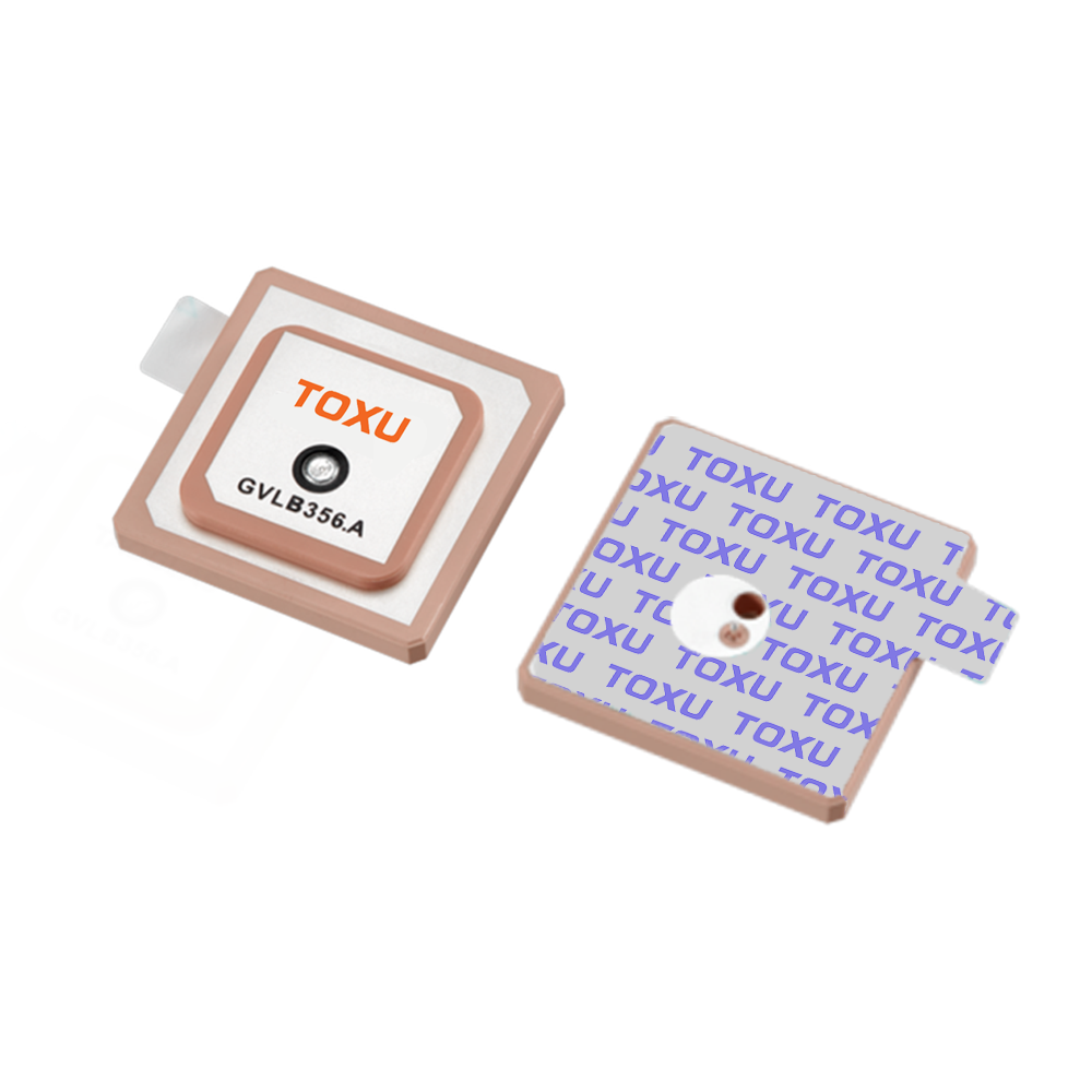
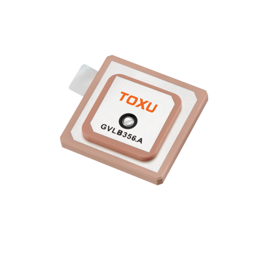
An integrated GNSS ceramic antenna is a highly specialized passive radiator, actively enhanced, designed to receive the faint, circularly polarized microwave signals transmitted by satellite constellations including the American GPS, Russian GLONASS, European Galileo, and Chinese BeiDou systems. The term "integrated" is a key differentiator; it signifies that the component is not merely a simple radiating element but a complete RF (Radio Frequency) front-end subsystem. This integration typically encompasses the ceramic patch radiator itself, a ground plane, a Low-Noise Amplifier (LNA), impedance matching circuits, and often advanced bandpass or SAW (Surface Acoustic Wave) filters, all housed within a single, compact, and shielded surface-mount device (SMD) package.
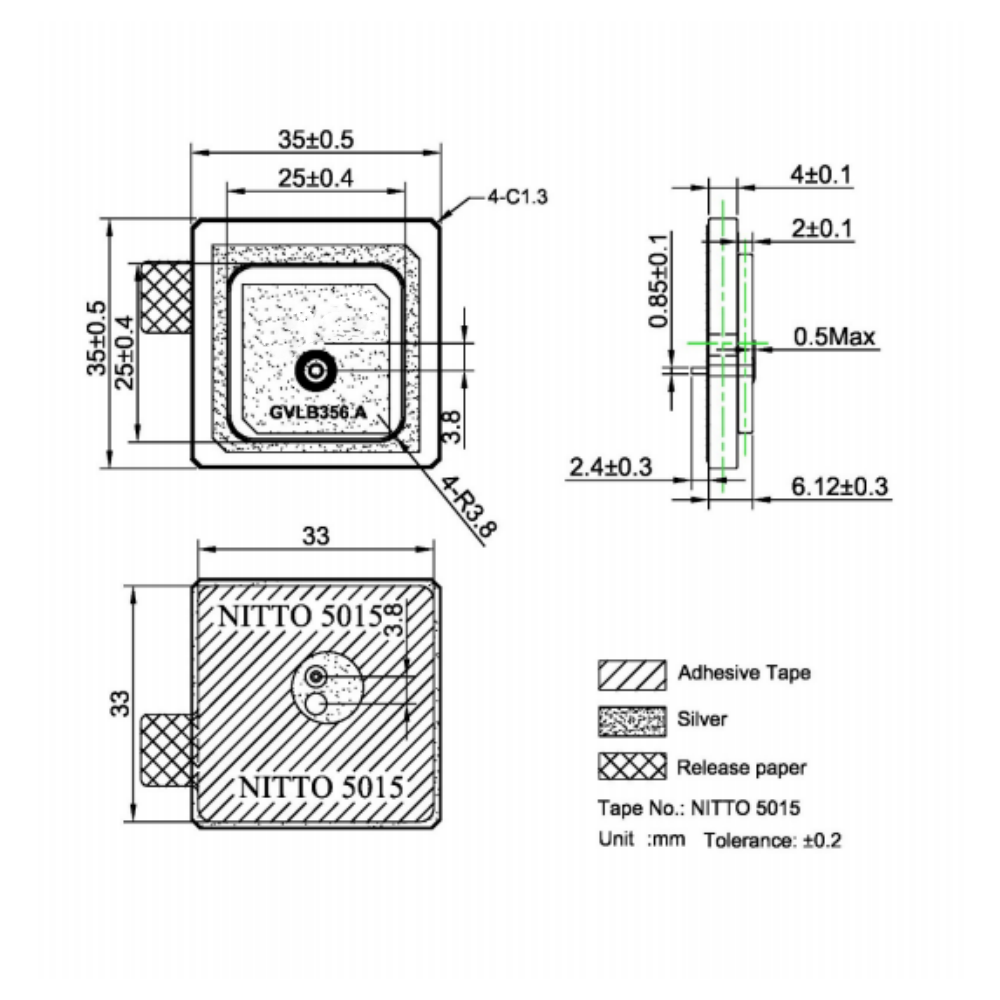
The choice of "ceramic" as the substrate material is the cornerstone of its design philosophy. Unlike conventional antennas that use materials like FR4 (fiberglass) or other plastics with low dielectric constants (εr ~4.5), these antennas utilize engineered ceramic compounds with a very high dielectric constant, typically ranging from 20 to over 40. This property is revolutionary because the physical size of an antenna is inversely proportional to the square root of the dielectric constant of its substrate. A high εr drastically reduces the wavelength within the material, allowing the antenna to resonate at the target GNSS frequencies (primarily 1.57542 GHz for the L1 band) while maintaining an exceptionally small form factor, often as compact as 10mm x 10mm x 4mm.
The historical context of this antenna's rise is linked to the commercialization of GPS in the 1980s and 1990s. Early receivers relied on larger, external helical or quadrifilar helix antennas, which were impractical for mass-market devices. The patch antenna, borrowed from aerospace and satellite communication technology, offered a low-profile, planar alternative. The subsequent integration of this design with high-dielectric ceramics was the breakthrough that enabled its proliferation into personal navigation devices (PNDs) and, most significantly, the smartphone, catalyzing the location-based services economy.
Today, the integrated ceramic patch antenna is a masterpiece of modern electronics. It is a commodity component that is simultaneously a high-tech marvel. Its success is attributed to its perfect alignment with industry needs: it is miniature, lightweight, cost-effective at scale, mechanically robust, and amenable to fully automated PCB assembly. Its integrated LNA ensures that the incredibly weak satellite signals—which can be as low as -130 dBm upon reaching the Earth's surface—are amplified before being sent to the receiver IC, preserving the crucial signal-to-noise ratio (SNR) necessary for acquiring a position fix. From wearable tech and drones to automotive telematics and smart city infrastructure, this antenna is the silent enabler, a testament to how a deeply engineered component can become an invisible, yet indispensable, part of daily life.
The architecture of an integrated GNSS ceramic antenna is a sophisticated layered structure, a product of meticulous electromagnetic simulation and precision manufacturing. Its design is a complex balancing act between achieving optimal electrical performance, mechanical robustness, and manufacturability. Deconstructing its build reveals the engineering ingenuity behind its compact form.
1. The Ceramic Core Substrate:
This is the fundamental element from which the antenna derives its name and primary characteristic: miniaturization. The substrate is a monolithic block of a specially formulated ceramic powder (often based on alumina, titanates, or other proprietary compounds) that is pressed and sintered at high temperatures. The two most critical properties of this ceramic are:
High Dielectric Constant (εr): As established, this allows for a drastic physical size reduction. The exact value of εr is a key design parameter chosen based on the desired size and bandwidth.
Low Loss Tangent (tan δ): This measures the inherent dissipation factor of the material—how much of the RF energy is lost as heat rather than being radiated. A very low tan δ (e.g., < 0.002) is non-negotiable for achieving high antenna efficiency, as any loss directly attenuates the already-weak GNSS signals.
2. The Radiating Element:
On the top surface of the ceramic block, a conductive radiating patch is formed. This is typically done using thick-film printing of a silver-based conductive paste, which is then fired to fuse it onto the ceramic. Alternatively, plating techniques can be used. The precise dimensions of this patch—primarily its length and width—determine the antenna's resonant frequency. The patch is almost always square or rectangular to support dual orthogonal modes necessary for circular polarization.
3. The Ground Plane:
The entire bottom surface of the ceramic block is metallized, creating a solid ground plane. This is not merely a reference point; it is an active part of the antenna structure. The patch, the dielectric substrate, and the ground plane form a resonant cavity. The ground plane's size and integrity are crucial for proper antenna performance, influencing bandwidth, radiation pattern, and front-to-back ratio.
4. The Feed Mechanism:
This is the interface that transfers energy between the radiating patch and the transmission line (typically a 50-ohm microstrip line on the host PCB). Common techniques include:
Probe Feed: A conductive pin is connected directly from the ground plane, through a hole in the substrate, to the patch. It's a simple and common method but can introduce parasitic inductance.
Aperture-Coupled Feed: A more advanced technique where the patch is electromagnetically coupled to a microstrip feedline located on a separate layer beneath the ground plane through a slot etched in the ground plane. This provides excellent isolation between the feed network and the radiator, allowing for more design flexibility and better impedance matching.
5. The Active Components (The "Integrated" Part):
This is what transforms a passive antenna into an active subsystem. A small printed circuit board is often used to host these components, which are then connected to the ceramic element.
Low-Noise Amplifier (LNA): This is the most critical active component. It is placed electrically immediately after the radiating element. Its purpose is to amplify the received signal (typically by 15 to 28 dB) while adding the absolute minimum amount of self-generated electronic noise, quantified by its Noise Figure (NF), which is ideally below 1 dB. The LNA requires a DC power supply, which is usually provided through the same RF output cable via a Bias-T circuit.
Filters: Bandpass filters are essential to reject powerful out-of-band interference from cellular, WiFi, and Bluetooth radios that share the device. SAW filters are often used for their sharp roll-off and excellent rejection characteristics.
Matching Circuits: Small capacitors and inductors are used to fine-tune the impedance match between the antenna element and the LNA input, ensuring maximum power transfer.
6. Packaging and Shielding:
The entire assembly is encapsulated in a protective package. This usually consists of a metal shield can that is soldered to the host PCB, creating a Faraday cage that protects the sensitive LNA and filter circuitry from external electromagnetic interference (EMI). The top of the package over the radiating patch is made of a low-loss plastic material (like LCP) that is transparent to RF signals, allowing the satellite signals to pass through unimpeded.
The entire design process is heavily reliant on 3D electromagnetic simulation software (e.g., CST Studio Suite, ANSYS HFSS). Engineers simulate countless iterations of patch dimensions, feed positions, and ground plane sizes to optimize performance parameters like return loss (S11), bandwidth, radiation pattern, gain, and axial ratio before a physical prototype is ever built. This virtual modeling is essential for managing the complex interactions within this highly integrated module.
The operation of an integrated GNSS ceramic antenna is an elegant demonstration of applied electromagnetics, converting free-space propagating waves into a guided, amplified electrical signal with high fidelity. Its function can be broken down into three core physical principles: resonance, circular polarization, and low-noise amplification.
1. Resonance and Radiation:
The antenna operates as a half-wave resonant cavity. The length of the patch element is carefully designed to be approximately half of the wavelength of the target GNSS frequency within the high-dielectric ceramic material. This effective wavelength (λ_eff) is given by λ_eff = λ_0 / √εr, where λ_0 is the free-space wavelength (~190mm for 1.575 GHz). This resonance establishes strong standing waves of electric field between the patch edges and the ground plane. The primary radiation mechanism is from the "fringing fields" at the edges of the patch. These oscillating fields launch electromagnetic waves into space during transmission or, in reception mode, induce a voltage on the patch when impinged by an incoming wave.
2. Generating Circular Polarization:
GNSS satellites transmit Right-Hand Circularly Polarized (RHCP) signals to mitigate signal degradation caused by atmospheric conditions and to avoid polarization mismatch with receivers at any orientation. A simple patch antenna is linearly polarized, which would incur a significant 3 dB loss when receiving a CP signal. To become circularly polarized, the antenna must radiate two orthogonal electric field components of equal amplitude with a 90-degree phase difference between them.
This is achieved by introducing a deliberate asymmetry in the patch structure. The most common method is to truncate two opposite corners of the square patch. This perturbation splits the natural resonant frequency into two slightly separated frequencies for two orthogonal modes. At the precise center frequency between these two splits, the conditions for circular polarization are met: equal amplitude and a 90-degree phase shift. The hand of polarization (left or right) is determined by which corners are truncated. The quality of the circular polarization is measured by the Axial Ratio (AR), with a perfect CP wave having an AR of 0 dB (1:1). A well-designed antenna will have a low AR (e.g., < 3 dB) over a wide angular cone, ensuring consistent performance regardless of the satellite's position in the sky.
3. The Signal Chain in Reception:
This is where the "integration" proves its worth:
Capture: An RHCP wave from a satellite arrives at the antenna.
Conversion: The wave's energy couples into the fringing fields of the patch, inducing a tiny oscillating current at the feed point. This creates a minuscule voltage, the RF signal, at the antenna's output port.
Pre-Filtering (Optional): The signal may first pass through a filter to attenuate very strong out-of-band interferers before they can overload the LNA.
Critical Amplification: The extremely weak signal (often <-130 dBm) is fed directly into the LNA. The LNA's high gain boosts its power level by a factor of 100 to 1000 (20-30 dB). Crucially, its low noise figure ensures it adds almost no additional noise in this process. This step is vital because it amplifies the signal before it travels through any lossy transmission line (like a coaxial cable) to the receiver chip, thereby preserving the Signal-to-Noise Ratio (SNR).
Post-Amplification Filtering: The now-amplified signal passes through the main bandpass filter to remove wideband noise generated by the LNA itself and to provide final rejection of off-frequency interference.
Output: The cleaned, amplified signal is delivered to the GNSS receiver IC via a 50-ohm transmission line for decoding, correlation, and position calculation.
In essence, the ceramic patch acts as a transducer, the filters act as bouncers excluding unwanted signals, and the LNA acts as a megaphone for the faint cosmic whisper. This seamless integration within a single package is what makes reliable, high-performance GNSS possible in small, consumer-grade devices.
The dominance of the integrated ceramic patch antenna is a direct result of its compelling advantages. However, its specific design philosophy also introduces inherent limitations and challenges that engineers must carefully address during system design.
Advantages:
Unmatched Miniaturization: The primary advantage. The high dielectric constant allows for a physical size that is an order of magnitude smaller than a patch antenna designed on a standard PCB substrate. This is the enabling factor for its use in phones, wearables, and other space-constrained applications.
Robust Mechanical Properties: The solid ceramic core and SMD package make the antenna highly resistant to shock, vibration, corrosion, and wear. It has no fragile protruding elements, making it ideal for the harsh environments of automotive, industrial, and outdoor applications.
Simplified Integration and Manufacturing: As a surface-mount component, it can be placed and soldered onto a PCB using fully automated assembly lines alongside other components. This eliminates the need for manual assembly of external antennas, reduces labor costs, and ensures high manufacturing consistency and reliability.
Superior Performance in a Package: The integration of the LNA at the antenna port provides a significant system-level advantage. It effectively eliminates the impact of transmission line loss on the system noise figure, which is critical for maintaining sensitivity. The built-in filtering protects the receiver from in-band interference.
Good Radiation Characteristics: The antenna naturally has a hemispherical radiation pattern, providing wide angular coverage of the sky above the horizon, which is ideal for receiving signals from satellites at various elevations.
Cost-Effectiveness at Scale: While the ceramic material and specialized design have a higher initial cost than a simple PCB trace antenna, the overall system cost is often lower due to simplified assembly and the elimination of separate connectors and cables. At high volumes, the unit cost becomes very competitive.
Challenges and Limitations:
Inherently Narrow Bandwidth: This is the most significant trade-off. The bandwidth of a microstrip patch antenna is inversely proportional to the dielectric constant and the Q-factor of the substrate. The very high εr that enables miniaturization also severely limits the instantaneous bandwidth. While sufficient for single-band GNSS (e.g., L1), this becomes a major challenge for designing multi-band antennas (L1/L2/L5) that require a much wider bandwidth. Complex techniques like stacking patches are needed, increasing cost and height.
Ground Plane Dependence: The antenna's performance is not isolated; it is heavily influenced by the size and layout of the host PCB's ground plane, to which it is directly connected. The PCB itself becomes part of the radiating system. A small or irregularly shaped ground plane can detune the antenna's resonant frequency, distort its radiation pattern, and create nulls in certain directions. This necessitates careful co-design of the antenna and the device's main board.
Environmental Sensitivity: Performance can be degraded by the immediate operating environment. The presence of nearby metal components, batteries, or the user's hand (in a phone) can detune the antenna and block its view of the sky. This is a constant challenge for device designers, who must often perform extensive testing and tuning for specific device enclosures.
Thermal Considerations: The LNA consumes power and generates heat. In a small, sealed package, managing thermal dissipation can be an issue, especially in automotive applications under direct sunlight. Temperature changes can also cause the ceramic's dielectric constant to drift slightly, potentially shifting the resonant frequency.
Cost and Complexity for Advanced Designs: Standard single-band L1 antennas are commodity items. However, developing high-performance, multi-band, multi-constellation antennas with stable performance across temperature requires advanced materials and complex design, leading to a significantly higher unit cost.
Limited Low-Elevation Performance: While the hemispherical pattern is generally good, the gain at very low elevation angles (near the horizon) is often poorer than that of a specialized geodetic antenna. This can make acquiring satellites at the horizon more difficult, though modern receivers with large satellite constellations have mitigated this issue.
In summary, the integrated ceramic patch antenna offers a best-in-class solution for size, integrability, and overall performance for most mass-market applications. Its challenges are well-known and can be effectively managed through careful system-aware design, making it the unequivocal choice for the vast majority of modern GNSS applications.
The integrated GNSS ceramic antenna is a versatile workhorse whose applications span from the mundane to the mission-critical. Its evolution is continuously driven by the demands of new technologies and the ever-increasing need for higher precision and reliability.
Applications:
Consumer Electronics: The highest volume market.
Smartphones and Tablets: Essential for navigation, location-based services (LBS), geotagging, and emergency services (E911).
Wearable Devices: Fitness trackers and smartwatches for activity tracking (running, cycling, hiking).
Personal Navigation Devices (PNDs): The original mass-market driver for this technology.
Cameras and Drones: For geotagging photos and providing essential navigation and stabilization for Unmanned Aerial Vehicles (UAVs).
Automotive and Telematics:
Telematics Control Units (TCUs): For emergency call systems (eCall), stolen vehicle tracking, and usage-based insurance (UBI).
Advanced Driver-Assistance Systems (ADAS): Provides absolute positioning data that is fused with camera, radar, and lidar data for features like lane-keeping and adaptive cruise control.
Autonomous Vehicles: A critical sensor for localization, requiring high-integrity, multi-band GNSS antennas.
In-Vehicle Infotainment (IVI): For built-in navigation systems.
Industrial and Internet of Things (IoT):
Asset Tracking: Modules for tracking containers, trailers, and high-value assets across global supply chains.
Fleet Management: Devices for monitoring the location and efficiency of commercial trucking fleets.
Precision Agriculture: Guiding tractors for automated planting and harvesting with centimeter-level accuracy (using RTK correction).
Surveying and Construction: High-precision receivers used for mapping and machine control.
Timing and Synchronization: Providing precise Coordinated Universal Time (UTC) for telecommunications networks (e.g., 5G base stations) and power grids.
Marine and Aviation:
Recreational Marine: Chartplotters and fishfinders.
General Aviation: As a primary or backup navigation source.
Future Trends:
Multi-Band/Multi-Constellation Operation: The future is about leveraging all signals from all available constellations (GPS, Galileo, GLONASS, BeiDou, etc.) across multiple frequency bands (L1, L2, L5, E6). The L5 band, in particular, offers higher power and advanced civilian codes, enabling faster acquisition and more robust performance. Antennas will need to be wideband or have multiple resonators to cover these bands efficiently.
Demand for High-Precision: Technologies like Real-Time Kinematic (RTK) and Precise Point Positioning (PPP) are moving from niche survey applications into mass markets like automotive, robotics, and agriculture. This demands antennas with extremely stable Phase Center—the electrical point from which radiation appears to emanate. Any variation in this point with signal angle or frequency introduces measurable errors in precision positioning. Future designs will focus on maximizing phase center stability and uniformity.
Advanced Interference and Jamming Mitigation: The RF environment is becoming increasingly crowded and hostile. Future antennas will incorporate more sophisticated filtering techniques and may even feature adaptive nulling capabilities, where the antenna pattern can actively form a null in the direction of a jamming signal to maintain operation.
Tighter Integration (Antenna-in-Package): The trend is towards further integration. The next step is to co-package the GNSS antenna directly with the RF front-end and the GNSS system-on-chip (SoC) into a single module, creating a complete "GNSS engine" that simplifies design for device manufacturers.
Hybridization and Sensor Fusion: The GNSS antenna will not work in isolation. It will be part of a fused data suite that includes inertial measurement units (IMUs), cellular modems, UWB radios, and cameras to provide continuous and resilient positioning, especially in GNSS-denied environments like urban canyons and indoors.
Resilience for Safety-Critical Systems: For autonomous driving (AV) and urban air mobility (UAM), functional safety and integrity are paramount. Antennas will need features for self-monitoring, fault detection, and assurance that the signals being received are authentic and not malicious spoofing attacks.
The integrated ceramic patch antenna is thus a dynamically evolving technology, continuously adapting to meet the demands for greater precision, robustness, and integration in an increasingly connected and automated world.
Conclusion
The integrated GNSS ceramic antenna is a paradigm of successful technological translation. It represents the culmination of a journey from a theoretical electromagnetic structure to a highly refined, mass-produced commodity that is fundamental to the global economy. Its development is a story of overcoming fundamental physical constraints—namely the relationship between wavelength, size, and efficiency—through innovative materials science and clever electronic integration.
Its core value proposition remains unshaken: it provides the most effective means to miniaturize a high-performance GNSS front-end into a form factor that is compatible with the sleek, consumer-oriented devices that define the modern era. The decision to integrate a low-noise amplifier and filtering directly within the antenna package was a masterstroke, solving the critical problem of signal degradation before it even reaches the receiver and simplifying the design process for countless product engineers. This has democratized access to reliable satellite positioning, empowering a revolution in location-based services, personal navigation, and asset tracking.
However, as with all engineered solutions, it is defined by its compromises. The pursuit of miniaturization via high-dielectric ceramics inherently limits bandwidth and creates a dependence on the installation environment. These are not mere drawbacks but rather defining parameters that shape how the technology is used and advanced. The ongoing research and development in this field are directly focused on pushing these boundaries: developing new ceramic composites for wider bandwidth, creating novel structures for stable multi-band operation, and integrating smarter features for interference mitigation.
In the grand architecture of a GNSS receiver, the antenna is the gateway. It is the first and most critical link in the chain. The integrated ceramic patch antenna has proven to be an exceptionally reliable, robust, and efficient gateway for a generation of devices. As we stand on the brink of a new era of autonomy—with self-driving cars, intelligent drones, and pervasive IoT—the demands on this humble component will only grow. Its ability to evolve, providing ever-higher levels of precision, integrity, and resilience, will be a key enabler for these future technologies. The integrated ceramic patch antenna, therefore, is far more than a simple component; it is a foundational technology that has quietly helped build our location-aware world and will continue to be a critical enabler for the intelligent systems of tomorrow.

 86 0755 2819 9597
Lucy Yang | lucy.y@toxutech.com
Nicole Li | nicole@toxutech.com
Dotty Zhao | sales04@toxutech.com
Global Business Director / Sales Team / Global Operations


 En
En Cn
Cn Korean
 Home >


