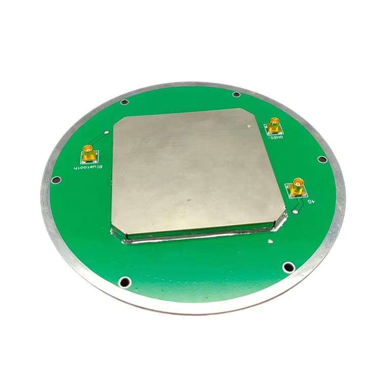
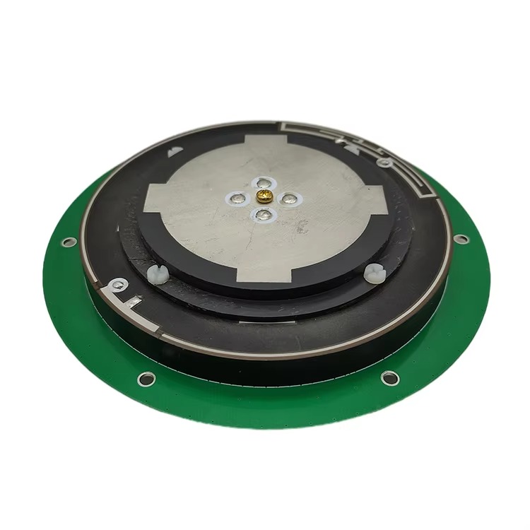
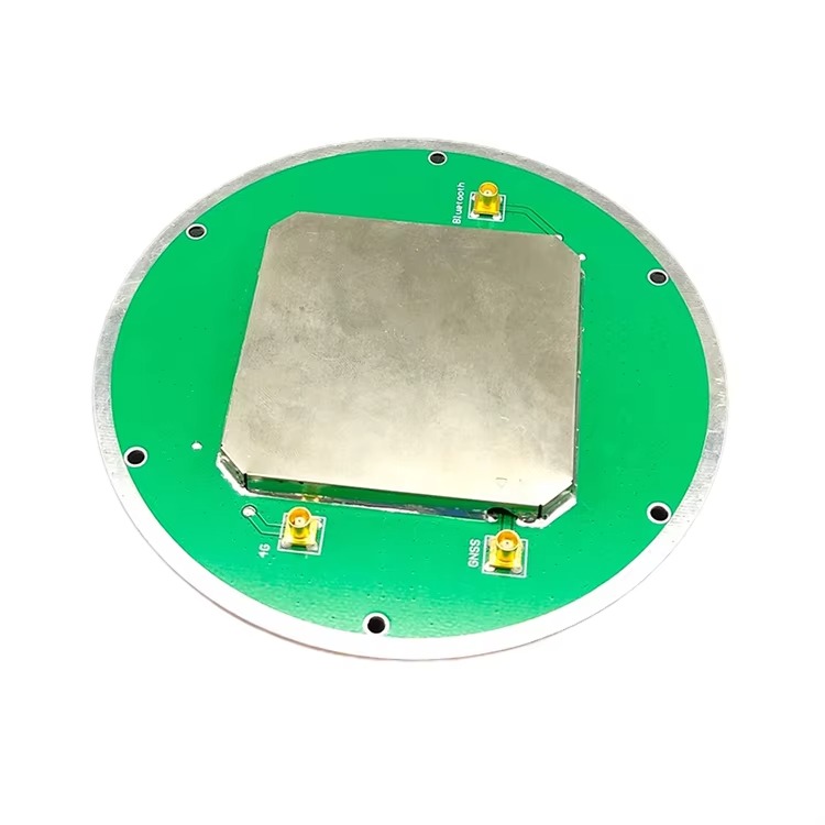
In the rapidly evolving landscape of Global Navigation Satellite System (GNSS) technology, Real - Time Kinematic (RTK) positioning has become the gold standard for applications demanding centimeter - level accuracy. At the heart of every high - performance GNSS RTK system lies an antenna that can efficiently capture weak satellite signals while minimizing noise and interference. Among the various antenna technologies available today, the integrated GNSS RTK ceramic patch antenna has emerged as a game - changer, especially in scenarios where size, weight, and integration flexibility are critical.
GNSS RTK systems rely on the reception of signals from multiple satellite constellations, including GPS, GLONASS, Galileo, and BeiDou. These signals travel vast distances from satellites orbiting the Earth, and by the time they reach the Earth's surface, their power levels are extremely low, often in the range of -130 dBm to -150 dBm. This makes the antenna's ability to capture these signals with high sensitivity and low noise floor a paramount consideration. The ceramic patch antenna, with its unique material properties and structural design, is well - suited to meet these demanding requirements.
Ceramic patch antennas are a type of microstrip antenna, characterized by a thin, flat patch of conductive material (typically copper) printed on a dielectric ceramic substrate. The integration aspect of these antennas refers to the seamless combination of the antenna element with other critical components, such as low - noise amplifiers (LNAs), filters, and sometimes even voltage - controlled oscillators (VCOs), into a single, compact module. This integration not only reduces the overall size and weight of the antenna system but also minimizes signal losses that can occur when components are connected via external cables.
One of the key advantages of ceramic as a substrate material is its high dielectric constant (εr). Ceramic materials used in these antennas, such as alumina (Al₂O₃) or barium titanate (BaTiO₃) - based composites, typically have dielectric constants ranging from 10 to 100. A high dielectric constant allows for a significant reduction in the physical size of the antenna. For example, a ceramic patch antenna operating at the GPS L1 frequency (1575.42 MHz) can have a patch size as small as 10 mm × 10 mm, making it ideal for integration into compact devices like smartphones, wearables, and small unmanned aerial vehicles (UAVs).
Integrated GNSS RTK ceramic patch antennas are designed to operate across multiple frequency bands to support various GNSS constellations. They can typically receive signals from GPS (L1, L2, L5), GLONASS (G1, G2, G3), Galileo (E1, E5a, E5b), and BeiDou (B1, B2, B3) bands. This multi - band capability ensures that the antenna can track a large number of satellites simultaneously, which is essential for achieving high - precision RTK positioning, especially in challenging environments where satellite visibility may be limited, such as urban canyons or dense forests.
Another important characteristic of these antennas is their polarization. Most GNSS satellites transmit circularly polarized (CP) signals, and thus, the antenna must be able to receive CP signals efficiently. Ceramic patch antennas can be designed to provide circular polarization by incorporating specific structural features, such as truncated corners, slits, or proximity - coupled feeds. This ensures that the antenna can maximize the reception of satellite signals, regardless of the satellite's orientation relative to the antenna.
In recent years, the demand for integrated GNSS RTK ceramic patch antennas has grown significantly, driven by the expansion of applications such as precision agriculture, autonomous driving, UAV - based mapping and surveying, and smart city infrastructure. These applications require not only high accuracy but also compact, lightweight, and cost - effective antenna solutions, which the integrated ceramic patch antenna is well - positioned to provide.
2.1 Ceramic Substrate Selection and Preparation
The ceramic substrate is the foundation of the integrated GNSS RTK ceramic patch antenna, and its selection is critical to the antenna's performance. The key parameters considered when choosing a ceramic substrate include dielectric constant (εr), loss tangent (tanδ), thermal conductivity, and mechanical strength.
Dielectric constant (εr) directly affects the size of the antenna. A higher εr allows for a smaller patch size, which is desirable for compact applications. However, a very high εr can also lead to increased surface wave losses and reduced bandwidth. Therefore, a balance must be struck between size reduction and performance. For GNSS RTK applications, ceramic substrates with εr values in the range of 20 to 40 are commonly used. For example, alumina - based ceramics with εr ≈ 9.8 are suitable for some applications, while barium titanate - based ceramics with εr up to 100 can be used for ultra - compact designs.
Loss tangent (tanδ) is a measure of the energy loss in the substrate material. A low tanδ is essential for minimizing signal attenuation and ensuring high antenna efficiency. Ceramic materials typically have very low tanδ values (on the order of 0.0001 to 0.001 at GNSS frequencies), which makes them ideal for high - performance antennas. This low loss ensures that most of the energy is radiated as electromagnetic waves rather than being dissipated as heat in the substrate.
Thermal conductivity is another important factor, especially in integrated antennas where LNAs and other active components are mounted on the same substrate. A high thermal conductivity substrate helps dissipate the heat generated by these active components, preventing overheating and ensuring stable performance over a wide temperature range. Alumina ceramics, for instance, have a thermal conductivity of approximately 30 W/(m·K), which is significantly higher than that of organic substrates like FR4 (≈0.25 W/(m·K)).
Mechanical strength is crucial for ensuring the antenna's durability, especially in harsh environments such as industrial settings or outdoor applications. Ceramic substrates are inherently strong and rigid, with high compressive strength and resistance to wear and tear. They can withstand mechanical shocks and vibrations, making them suitable for use in devices that are subject to rough handling or dynamic operating conditions.
The preparation of the ceramic substrate involves several steps, including powder mixing, shaping, sintering, and polishing. First, the ceramic powder (e.g., alumina or barium titanate) is mixed with binders and solvents to form a homogeneous slurry. This slurry is then shaped into the desired substrate form using techniques such as tape casting, pressing, or injection molding. After shaping, the substrate is sintered at high temperatures (typically between 1200°C and 1600°C) to densify the material and achieve the desired dielectric and mechanical properties. Finally, the surface of the substrate is polished to ensure a smooth, flat surface for the deposition of the conductive patch and other components.
2.2 Patch Element Design
The patch element is the radiating part of the ceramic patch antenna, and its design directly determines the antenna's frequency response, polarization, gain, and bandwidth. The patch is typically made of a thin layer of conductive material, such as copper, silver, or gold, which is deposited on the top surface of the ceramic substrate using techniques like sputtering, evaporation, or screen printing.
The dimensions of the patch element are calculated based on the dielectric constant of the substrate and the desired operating frequency. The length (L) and width (W) of the patch can be approximated using the following formulas:
W = c / (2f₀√((εr + 1)/2))
where c is the speed of light in free space (≈3×10⁸ m/s), f₀ is the center frequency of the antenna, and εr is the dielectric constant of the substrate.
The length L of the patch is slightly less than λ/2 (where λ is the wavelength in the substrate) to account for the fringing fields at the edges of the patch. The reduction in length (ΔL) can be estimated using empirical formulas based on the substrate thickness (h) and dielectric constant.
For multi - band operation, which is essential for GNSS RTK applications, the patch element can be designed with multiple resonant structures. One common approach is to use a stacked patch design, where two or more patch elements are stacked vertically on top of each other, separated by thin dielectric layers. Each patch element is tuned to a different frequency band, allowing the antenna to operate across multiple GNSS bands. For example, a stacked patch antenna can be designed to cover the GPS L1 (1575.42 MHz) and L5 (1176.45 MHz) bands, as well as the Galileo E1 (1575.42 MHz) and E5b (1207.14 MHz) bands.
Another approach for multi - band operation is to use a single patch with slots or notches cut into it. These slots introduce additional resonant frequencies, allowing the antenna to operate at multiple bands. For example, a rectangular patch with a U - shaped slot can be designed to resonate at two different frequencies, covering two GNSS bands. This approach is simpler and more compact than the stacked patch design but may have lower efficiency and higher cross - polarization levels.
Polarization is another critical aspect of the patch element design. As mentioned earlier, GNSS satellites transmit circularly polarized signals, so the antenna must be able to receive CP signals. There are several methods to achieve circular polarization in a ceramic patch antenna. One common method is to truncate the corners of the rectangular patch. By cutting off the corners of the patch, the antenna generates two orthogonal linear polarization modes that are out of phase by 90 degrees, resulting in circular polarization. The size of the truncated corners determines the axial ratio (AR) of the antenna, which is a measure of the quality of the circular polarization. A low axial ratio (typically less than 3 dB) is desired for efficient reception of GNSS signals.
Another method to achieve circular polarization is to use a proximity - coupled feed. In this design, the feed line is placed beneath the patch, separated by a thin dielectric layer. The feed line is designed to excite two orthogonal modes in the patch, which interfere to produce circular polarization. This method offers better control over the axial ratio and bandwidth but is more complex to fabricate.
2.3 Integration of Active and Passive Components
One of the key features of integrated GNSS RTK ceramic patch antennas is the integration of active components (such as LNAs) and passive components (such as filters and matching networks) into the antenna module. This integration offers several advantages, including reduced size, lower signal loss, and improved performance.
The low - noise amplifier (LNA) is a critical active component that amplifies the weak GNSS signals received by the antenna while adding minimal noise. The LNA is typically mounted directly on the ceramic substrate, close to the patch element, to minimize the length of the feed line between the antenna and the LNA. This reduces signal losses, which is essential for maintaining a high signal - to - noise ratio (SNR) of the received signals.
The design of the LNA for GNSS RTK applications requires a very low noise figure (NF), typically less than 2 dB, and high gain (typically 15 to 25 dB). The LNA must also have a wide bandwidth to cover all the GNSS bands of interest and high linearity to avoid distortion of the received signals, especially in the presence of strong interfering signals.
To achieve these performance metrics, the LNA is often designed using gallium arsenide (GaAs) or silicon germanium (SiGe) heterojunction bipolar transistors (HBTs) or metal - oxide - semiconductor field - effect transistors (MOSFETs). These technologies offer low noise, high gain, and wide bandwidth, making them suitable for GNSS applications.
In addition to the LNA, integrated GNSS RTK ceramic patch antennas also include passive components such as band - pass filters (BPFs) and matching networks. The band - pass filter is used to reject out - of - band interference, such as signals from cellular networks (e.g., 5G, LTE) or Wi - Fi devices, which can interfere with the reception of GNSS signals. The filter is typically placed between the LNA and the receiver to prevent the LNA from being saturated by strong interfering signals and to ensure that only the desired GNSS signals are passed to the receiver.
The matching network is used to match the impedance of the antenna to the impedance of the LNA and the receiver. Impedance matching is essential for maximizing power transfer between the antenna and the receiver, minimizing signal reflections, and ensuring optimal performance. The matching network is typically composed of passive components such as inductors, capacitors, and resistors, which are integrated into the ceramic substrate using surface - mount technology (SMT).
The integration of these components into the ceramic patch antenna module is achieved using advanced packaging technologies, such as multi - chip module (MCM) packaging or system - in - package (SiP) packaging. These technologies allow for the compact integration of multiple chips and components into a single package, reducing the overall size and weight of the antenna system.
2.4 Enclosure and Shielding
The enclosure of the integrated GNSS RTK ceramic patch antenna plays a crucial role in protecting the internal components from environmental factors such as dust, moisture, temperature extremes, and mechanical damage. The enclosure also provides electromagnetic shielding to reduce interference from external sources.
The enclosure material is typically a lightweight, durable plastic or composite material with good mechanical strength and environmental resistance. Materials such as polycarbonate (PC), acrylonitrile butadiene styrene (ABS), or glass - fiber - reinforced plastics (GFRP) are commonly used. These materials are resistant to impact, corrosion, and UV radiation, making them suitable for outdoor applications.
To ensure environmental protection, the enclosure is often designed to meet industry standards such as IP67 (Ingress Protection 67), which means it is completely dust - tight and can withstand immersion in water up to 1 meter for 30 minutes. This level of protection is essential for antennas used in harsh environments such as construction sites, agricultural fields, or marine applications.
Electromagnetic shielding is another important function of the enclosure. The enclosure can be coated with a thin layer of conductive material, such as copper or nickel, to provide a Faraday cage effect, which blocks external electromagnetic fields from entering the enclosure and interfering with the internal components. The shielding effectiveness of the enclosure depends on the thickness of the conductive coating, the quality of the seams and joints, and the presence of any openings (such as connectors or vents).
In addition to the enclosure, internal shielding can also be used to isolate the LNA and other sensitive components from each other and from the patch element. This is particularly important in multi - band antennas, where cross - talk between different frequency bands can degrade performance. Internal shielding can be achieved using metal partitions or conductive gaskets, which are integrated into the ceramic substrate or the enclosure.
3.1 Signal Reception and Conversion
The primary function of the integrated GNSS RTK ceramic patch antenna is to receive the weak electromagnetic signals transmitted by GNSS satellites and convert them into electrical signals that can be processed by the RTK receiver. The working principle of the antenna begins with the interaction between the incoming satellite signals and the patch element.
When a GNSS satellite signal reaches the Earth's surface, it interacts with the conductive patch element of the antenna. The patch element, which is resonant at the frequency of the incoming signal, absorbs the electromagnetic energy of the signal and converts it into an alternating electrical current. This current flows through the feed line to the LNA, which amplifies the signal to a level that can be processed by the receiver.
The key to efficient signal reception is the resonance of the patch element. The patch element is designed to have a resonant frequency that matches the frequency of the GNSS signals it is intended to receive. When the frequency of the incoming signal matches the resonant frequency of the patch, the patch element acts as a resonant circuit, maximizing the absorption of the signal energy.
The dielectric constant of the ceramic substrate plays a crucial role in determining the resonant frequency of the patch. As mentioned earlier, the size of the patch is inversely proportional to the square root of the dielectric constant of the substrate. A higher dielectric constant allows for a smaller patch size, but it also affects the resonant frequency. Therefore, the dielectric constant of the substrate must be carefully controlled during the manufacturing process to ensure that the patch element resonates at the correct frequency.
Another important factor in signal reception is the polarization of the antenna. As GNSS satellites transmit circularly polarized signals, the antenna must be able to receive these signals efficiently. The circular polarization of the ceramic patch antenna is achieved by generating two orthogonal linear polarization modes that are out of phase by 90 degrees. When a circularly polarized satellite signal arrives at the antenna, it excites both linear polarization modes, and the combination of these modes results in a circularly polarized current in the patch element. This current is then fed to the LNA for amplification.
3.2 Impedance Matching
Impedance matching is a critical aspect of the working principle of the integrated GNSS RTK ceramic patch antenna. The goal of impedance matching is to ensure that the impedance of the antenna matches the impedance of the LNA and the receiver, maximizing power transfer and minimizing signal reflections.
The impedance of a ceramic patch antenna is typically in the range of 50 to 100 ohms, depending on the design of the patch and the substrate. The impedance of the LNA and the receiver, on the other hand, is usually 50 ohms, which is the standard impedance for most RF systems. Therefore, a matching network is required to match the impedance of the antenna to the impedance of the LNA and the receiver.
The matching network is composed of passive components such as inductors, capacitors, and resistors, which are integrated into the ceramic substrate. The design of the matching network depends on the impedance of the antenna and the desired frequency range. For example, a simple L - network (composed of an inductor and a capacitor) can be used to match the impedance of the antenna to 50 ohms at a single frequency. For multi - band antennas, more complex matching networks, such as T - networks or π - networks, may be required to achieve impedance matching across multiple frequency bands.
Impedance matching is essential for maximizing the power transfer from the antenna to the receiver. If the impedance of the antenna does not match the impedance of the receiver, a portion of the signal energy will be reflected back from the receiver to the antenna, resulting in signal loss and reduced performance.To quantify the impact of impedance mismatch, we use the reflection coefficient (Γ), which is defined as the ratio of the reflected voltage to the incident voltage at the interface between the antenna and the receiver. The reflection coefficient can be calculated using the following formula:
Γ = (Zant - Zload) / (Zant + Zload)
where Zant is the impedance of the antenna and Zload is the impedance of the receiver (typically 50 ohms). The magnitude of the reflection coefficient (|Γ|) ranges from 0 to 1, where 0 indicates perfect matching (no reflection) and 1 indicates total reflection (no power transfer).
The power reflection coefficient (Γ²) is the square of the magnitude of the reflection coefficient and represents the fraction of the incident power that is reflected back from the receiver. The power transmission coefficient (T), which represents the fraction of the incident power that is transmitted to the receiver, is given by:
T = 1 - Γ²
For example, if the antenna impedance is 75 ohms and the receiver impedance is 50 ohms, the reflection coefficient is (75 - 50)/(75 + 50) = 0.2, the power reflection coefficient is 0.04, and the power transmission coefficient is 0.96. This means that 4% of the incident power is reflected back, and 96% is transmitted to the receiver. While this may seem like a small loss, in GNSS RTK applications where the received signal power is extremely low, even a small loss can significantly reduce the SNR and degrade the positioning accuracy.
To ensure optimal impedance matching across multiple GNSS bands, the matching network must be carefully designed and optimized. Advanced simulation tools, such as electromagnetic (EM) simulation software (e.g., ANSYS HFSS, CST Microwave Studio), are used to model the antenna and the matching network, predict their performance, and iterate on the design until the desired impedance matching is achieved. These tools allow engineers to analyze the impedance characteristics of the antenna over the entire frequency range of interest and design the matching network to compensate for any impedance variations.
3.3 Signal Amplification and Filtering
Once the received GNSS signals are converted into electrical signals and matched to the impedance of the LNA, they are fed into the LNA for amplification. The LNA is a critical component in the integrated GNSS RTK ceramic patch antenna, as it is responsible for amplifying the weak signals while adding minimal noise.
The performance of the LNA is characterized by several key parameters, including noise figure (NF), gain (G), bandwidth (BW), and linearity (IP3). The noise figure is a measure of the amount of noise added by the amplifier to the received signal. A low noise figure is essential for maintaining a high SNR, which is critical for detecting the weak GNSS signals. For GNSS RTK applications, the LNA typically has a noise figure of less than 2 dB, which means that the amplifier adds very little noise to the signal.
The gain of the LNA is the ratio of the output signal power to the input signal power. A high gain is required to amplify the weak input signals (which may be as low as -150 dBm) to a level that can be processed by the receiver (typically around -120 dBm to -100 dBm). The gain of the LNA for GNSS RTK applications is typically in the range of 15 to 25 dB. However, the gain must be carefully balanced with the linearity of the amplifier. If the gain is too high, the LNA may become saturated by strong interfering signals, leading to signal distortion and reduced performance.
The bandwidth of the LNA must be wide enough to cover all the GNSS bands of interest. For example, if the antenna is designed to operate across the GPS L1, L2, and L5 bands, the LNA must have a bandwidth that spans from approximately 1176 MHz (L5) to 1575 MHz (L1) and 1227 MHz (L2). A wide bandwidth ensures that the LNA can amplify signals from all the desired bands without introducing significant gain variation.
Linearity is another important parameter of the LNA, as it determines the amplifier's ability to handle strong interfering signals without distortion. The third - order intercept point (IP3) is a common measure of linearity. A high IP3 indicates that the amplifier can handle stronger interfering signals before distortion occurs. For GNSS RTK applications, the LNA must have a high IP3 to avoid distortion caused by strong out - of - band signals, such as those from cellular networks or Wi - Fi devices.
After amplification by the LNA, the signals pass through a band - pass filter (BPF) to reject out - of - band interference. The BPF is designed to allow only the desired GNSS signals to pass through while attenuating signals outside the GNSS frequency bands. The filter's passband is carefully tuned to match the frequency bands of the antenna, ensuring that all the desired signals are passed to the receiver.
The performance of the BPF is characterized by its insertion loss, stopband attenuation, and roll - off rate. The insertion loss is the amount of signal power lost as the signal passes through the filter. A low insertion loss is desirable to minimize signal attenuation, especially since the signals have already been amplified by the LNA. The stopband attenuation is the amount of attenuation provided to signals outside the passband. A high stopband attenuation is required to effectively reject interfering signals. The roll - off rate is the rate at which the filter's attenuation increases outside the passband. A steep roll - off rate allows the filter to closely match the desired frequency bands, minimizing the rejection of desired signals and maximizing the attenuation of interfering signals.
In integrated GNSS RTK ceramic patch antennas, the BPF is typically a surface - mount device (SMD) that is integrated into the ceramic substrate along with the LNA and the matching network. This integration ensures that the filter is placed close to the LNA, minimizing the length of the signal path between the two components and reducing signal losses.
3.4 Interaction with RTK Receiver
The final step in the working principle of the integrated GNSS RTK ceramic patch antenna is the interaction with the RTK receiver. After the signals have been amplified by the LNA and filtered by the BPF, they are sent to the RTK receiver for further processing.
The RTK receiver uses the received signals to calculate the position of the antenna. The receiver first demodulates the signals to extract the navigation data transmitted by the satellites, which includes information about the satellite's orbit (ephemeris data) and clock corrections. Using this information, the receiver can calculate the distance between the antenna and each satellite (pseudorange).
In RTK positioning, the receiver also uses a correction signal from a base station. The base station is a fixed - position receiver that has a known precise location. The base station calculates the pseudoranges to the same satellites as the rover (the integrated GNSS RTK ceramic patch antenna and its associated receiver) and compares them to the known distances based on its fixed position. The difference between the calculated pseudoranges and the known distances is the error, which is transmitted to the rover as a correction signal.
The rover receiver uses the correction signal to adjust its own pseudorange measurements, eliminating most of the common errors, such as satellite clock errors, ionospheric delays, and tropospheric delays. This allows the rover to achieve centimeter - level positioning accuracy.
The integrated GNSS RTK ceramic patch antenna plays a critical role in this process by providing the receiver with high - quality, low - noise signals. The antenna's ability to capture weak signals with high sensitivity, reject interference, and maintain a high SNR ensures that the receiver can accurately demodulate the navigation data and calculate the pseudoranges. Without a high - performance antenna, the RTK receiver would not be able to achieve the centimeter - level accuracy required for many applications.
4.1 Advantages
4.1.1 Compact Size and Lightweight Design
One of the most significant advantages of integrated GNSS RTK ceramic patch antennas is their compact size and lightweight design. The use of a high - dielectric - constant ceramic substrate allows for a significant reduction in the size of the patch element. As mentioned earlier, a ceramic patch antenna operating at the GPS L1 frequency can have a patch size as small as 10 mm × 10 mm. When integrated with other components such as the LNA, filter, and matching network into a single module, the overall size of the antenna system is typically less than 20 mm × 20 mm × 5 mm, making it ideal for integration into compact devices.
The lightweight nature of these antennas is another key advantage. Ceramic substrates are relatively lightweight, and the use of surface - mount components further reduces the weight. The total weight of an integrated GNSS RTK ceramic patch antenna module is typically less than 10 grams, which is significantly lighter than other types of GNSS antennas, such as helical antennas or patch antennas based on organic substrates. This lightweight design is particularly important for applications such as UAVs, wearables, and portable navigation devices, where weight is a critical factor that affects performance and usability.
For example, in UAV - based mapping and surveying applications, the weight of the payload (including the GNSS antenna) directly affects the flight time and maneuverability of the UAV. A lightweight integrated ceramic patch antenna allows the UAV to carry more other payloads (such as cameras or sensors) or fly for longer periods, improving the efficiency and productivity of the mapping or surveying mission.
4.1.2 High Integration Level
The high integration level of integrated GNSS RTK ceramic patch antennas is another major advantage. By integrating the antenna element, LNA, filter, and matching network into a single module, these antennas eliminate the need for external cables and connectors between the components. This not only reduces the overall size and weight of the antenna system but also minimizes signal losses that can occur when components are connected via external cables.
External cables and connectors introduce additional resistance, capacitance, and inductance into the signal path, which can cause signal attenuation and reflection. In GNSS applications, where the received signal power is extremely low, even small signal losses can significantly reduce the SNR and degrade the positioning accuracy. By integrating all the components into a single module, the signal path is minimized, and the signal losses are reduced to a minimum.
The high integration level also simplifies the design and assembly of the overall system. Instead of sourcing and integrating multiple discrete components (antenna, LNA, filter, etc.), the system designer can simply integrate a single integrated antenna module into the device. This reduces the complexity of the system design, shortens the development time, and lowers the manufacturing cost.
For example, in the design of a smartphone with GNSS RTK capabilities, the integration of the antenna, LNA, and filter into a single module allows the smartphone manufacturer to save space on the circuit board and simplify the assembly process. This not only reduces the cost of the smartphone but also improves its reliability, as there are fewer components and connections that can fail.
4.1.3 High Performance in Challenging Environments
Integrated GNSS RTK ceramic patch antennas offer high performance in challenging environments, such as urban canyons, dense forests, and high - interference areas. This is due to several factors, including their multi - band capability, circular polarization, and excellent interference rejection.
The multi - band capability of these antennas allows them to track a large number of satellites from multiple constellations. In urban canyons, where satellite visibility is limited due to tall buildings, the ability to track satellites from multiple constellations increases the number of available satellites, improving the positioning accuracy and reliability. For example, if the GPS signals are blocked by a tall building, the antenna can still track signals from GLONASS, Galileo, or BeiDou satellites, ensuring that the RTK receiver can continue to calculate the position.
The circular polarization of the antenna ensures that it can efficiently receive GNSS signals regardless of the satellite's orientation relative to the antenna. This is particularly important in dynamic environments, such as when the antenna is mounted on a moving vehicle or UAV, where the orientation of the antenna relative to the satellites is constantly changing. Linear polarized antennas, on the other hand, may experience significant signal loss if the polarization of the incoming signal is not aligned with the antenna's polarization axis.
The excellent interference rejection of integrated GNSS RTK ceramic patch antennas is due to the integration of the LNA and BPF. The LNA has a high linearity, which allows it to handle strong interfering signals without distortion. The BPF, on the other hand, rejects out - of - band interference, ensuring that only the desired GNSS signals are passed to the receiver. This makes the antenna suitable for use in high - interference areas, such as near cellular towers, Wi - Fi hotspots, or industrial facilities.
4.1.4 Cost - Effectiveness
Despite their high performance and advanced features, integrated GNSS RTK ceramic patch antennas are relatively cost - effective compared to other types of high - performance GNSS antennas. This is due to several factors, including the use of low - cost ceramic materials, the simplicity of the patch element design, and the high volume manufacturing capabilities of surface - mount technology.
Ceramic materials such as alumina are relatively inexpensive and widely available. The patch element is a simple, flat structure that can be manufactured using standard printed circuit board (PCB) techniques, such as screen printing or sputtering. The integration of the LNA, filter, and matching network using surface - mount technology allows for high - volume, automated manufacturing, which reduces the labor cost and improves the consistency of the product.
The cost - effectiveness of these antennas makes them suitable for a wide range of applications, from high - end precision agriculture and surveying equipment to consumer devices such as smartphones and wearables. For example, in the consumer market, the integration of GNSS RTK capabilities into smartphones requires a cost - effective antenna solution that can provide high accuracy without significantly increasing the cost of the device. Integrated GNSS RTK ceramic patch antennas meet this requirement, making them an ideal choice for consumer applications.
4.2 Challenges
4.2.1 Limited Bandwidth
One of the main challenges of integrated GNSS RTK ceramic patch antennas is their limited bandwidth. The bandwidth of a patch antenna is determined by several factors, including the dielectric constant of the substrate, the thickness of the substrate, and the design of the patch element. Ceramic substrates have a high dielectric constant, which reduces the size of the antenna but also narrows the bandwidth.
The bandwidth of a typical ceramic patch antenna is in the range of 1% to 5% of the center frequency. For example, an antenna operating at the GPS L1 frequency (1575.42 MHz) with a bandwidth of 2% can only cover a frequency range of approximately 31.5 MHz (from 1559.65 MHz to 1591.19 MHz). While this may be sufficient for a single GNSS band, it can be a limitation for multi - band antennas that need to cover a wide range of frequencies.
To overcome this limitation, antenna designers use various techniques to increase the bandwidth of ceramic patch antennas. One common technique is to use a stacked patch design, where two or more patch elements are stacked vertically on top of each other. Each patch element is tuned to a different frequency band, and the combination of the patches increases the overall bandwidth of the antenna. However, this technique increases the complexity and cost of the antenna, and it may also reduce the gain and efficiency.
Another technique to increase the bandwidth is to use a thick substrate with a low dielectric constant. A thick substrate reduces the surface wave losses and increases the bandwidth, but it also increases the size of the antenna, which is a trade - off for compact applications.
4.2.2 Sensitivity to Mechanical Deformation
Ceramic substrates are rigid and brittle, which makes them sensitive to mechanical deformation. Mechanical deformation, such as bending, twisting, or compression, can cause changes in the dimensions of the patch element and the substrate, which can shift the resonant frequency of the antenna and degrade its performance.
In applications where the antenna is subject to mechanical stress, such as in automotive or industrial environments, this sensitivity to mechanical deformation can be a significant problem. For example, in an autonomous vehicle, the antenna may be mounted on the roof or bumper of the vehicle, where it is exposed to vibrations, shocks, and temperature changes. These factors can cause the ceramic substrate to deform, leading to a shift in the resonant frequency of the antenna and a reduction in the positioning accuracy.
To address this challenge, antenna designers use various techniques to improve the mechanical robustness of the antenna. One technique is to use a reinforced ceramic substrate, such as a ceramic - composite substrate that includes fibers or particles to increase the strength and flexibility of the substrate. Another technique is to mount the antenna in a rigid enclosure that provides mechanical support and protects the substrate from deformation. However, these techniques increase the size and weight of the antenna, which may not be suitable for compact applications.
4.2.3 Temperature Sensitivity
The performance of integrated GNSS RTK ceramic patch antennas is also sensitive to temperature changes. The dielectric constant of ceramic materials changes with temperature, which can shift the resonant frequency of the antenna. In addition, the dimensions of the patch element and the substrate can change due to thermal expansion, which can also affect the resonant frequency and other performance parameters.
The temperature coefficient of the dielectric constant (τ ε) is a measure of the change in the dielectric constant with temperature. For ceramic materials, the τ ε can be positive or negative, depending on the composition of the material. For example, alumina has a positive τ ε, which means that the dielectric constant increases with temperature. This can cause the resonant frequency of the antenna to decrease with increasing temperature, as the resonant frequency is inversely proportional to the square root of the dielectric constant.
The thermal expansion coefficient (α) is a measure of the change in dimensions with temperature. Ceramic materials have a low thermal expansion coefficient compared to metals and plastics, but even small changes in dimensions can have a significant impact on the performance of the antenna. For example, a change in the length of the patch element by 0.1 mm can shift the resonant frequency by several MHz, which can cause the antenna to fall out of the desired frequency band.
To mitigate the effects of temperature changes, antenna designers use various techniques. One technique is to select ceramic materials with a low τ ε and α. For example, some barium titanate - based ceramics can be engineered to have a near - zero τ ε, which minimizes the change in the dielectric constantwith temperature. Another technique is to use a temperature - compensation network, which consists of passive components such as thermistors or varactors that adjust the impedance of the antenna or the matching network in response to temperature changes. For example, a thermistor with a negative temperature coefficient (NTC) can be integrated into the matching network. As the temperature increases, the resistance of the NTC decreases, which adjusts the impedance of the matching network to compensate for the change in the antenna's impedance caused by temperature. However, these temperature - compensation techniques add complexity to the antenna design and may increase the size and cost of the module.
4.2.4 Cross - Polarization Interference
Cross - polarization interference is another challenge faced by integrated GNSS RTK ceramic patch antennas. Although these antennas are designed to receive circularly polarized signals, they may still exhibit some level of cross - polarization, which refers to the antenna's ability to receive signals with the opposite polarization (e.g., left - hand circular polarization (LHCP) when the antenna is designed for right - hand circular polarization (RHCP)).
Cross - polarization is typically quantified by the axial ratio (AR) of the antenna. The axial ratio is the ratio of the major axis to the minor axis of the polarization ellipse, and a perfect circularly polarized antenna has an axial ratio of 1 (0 dB). In practice, ceramic patch antennas have an axial ratio of typically 3 dB or higher, which means that they can receive some cross - polarized signals.
Cross - polarized signals can come from various sources, such as reflected signals (multipath) or signals from satellites with the opposite polarization. These cross - polarized signals can interfere with the desired signals, reducing the SNR and degrading the positioning accuracy. For example, in an urban environment, signals reflected off buildings may change their polarization, becoming cross - polarized relative to the antenna's desired polarization. These cross - polarized reflected signals can be received by the antenna, leading to multipath interference and positioning errors.
To reduce cross - polarization interference, antenna designers use various techniques to improve the axial ratio of the antenna. One technique is to optimize the design of the patch element, such as adjusting the size of the truncated corners or the position of the feed line. Another technique is to use a dual - feed design, where two feed lines are used to excite the patch element at 90 degrees to each other, resulting in a more balanced circular polarization and a lower axial ratio. However, these techniques increase the complexity of the antenna design and may require more precise manufacturing processes.
5.1 Current Applications
5.1.1 Precision Agriculture
Precision agriculture is one of the key application areas for integrated GNSS RTK ceramic patch antennas. In precision agriculture, the goal is to optimize crop yields while minimizing the use of resources such as water, fertilizers, and pesticides. This requires accurate positioning of agricultural machinery, such as tractors, harvesters, and sprayers, to ensure that resources are applied only where they are needed.
Integrated GNSS RTK ceramic patch antennas are ideal for this application due to their compact size, lightweight design, and high precision. These antennas can be integrated into the navigation systems of agricultural machinery, providing centimeter - level positioning accuracy. For example, a tractor equipped with an integrated GNSS RTK ceramic patch antenna can follow a pre - defined path with an accuracy of less than 5 cm, ensuring that seeds are planted in straight rows and that fertilizers are applied evenly across the field.
In addition, these antennas can be used in unmanned aerial vehicles (UAVs) for agricultural monitoring and spraying. UAVs equipped with integrated GNSS RTK ceramic patch antennas can fly over fields with high precision, capturing images of crops to monitor their health and applying pesticides or fertilizers to specific areas. The lightweight design of the antenna ensures that the UAV can carry additional payloads, such as cameras or sprayers, and fly for longer periods.
5.1.2 Autonomous Driving
Autonomous driving is another important application area for integrated GNSS RTK ceramic patch antennas. Autonomous vehicles require accurate and reliable positioning to navigate safely on roads, avoid obstacles, and follow traffic rules. GNSS RTK technology, combined with other sensors such as lidar, radar, and cameras, provides the high - precision positioning required for autonomous driving.
Integrated GNSS RTK ceramic patch antennas are well - suited for this application due to their high integration level, excellent interference rejection, and compact size. These antennas can be integrated into the vehicle's navigation system, providing centimeter - level positioning accuracy even in challenging environments such as urban canyons. The multi - band capability of the antenna allows it to track signals from multiple GNSS constellations, ensuring that the vehicle has access to a sufficient number of satellites even when some signals are blocked by buildings or other obstacles.
The excellent interference rejection of the antenna is also critical in autonomous driving applications. Urban environments are filled with sources of electromagnetic interference, such as cellular towers, Wi - Fi hotspots, and other electronic devices. The integrated LNA and BPF in the antenna help to reject these interfering signals, ensuring that the vehicle's navigation system receives only the desired GNSS signals. This reduces the risk of positioning errors, which can lead to accidents.
5.1.3 Surveying and Mapping
Surveying and mapping is a traditional application area for GNSS RTK technology, and integrated GNSS RTK ceramic patch antennas are increasingly being used in this field. Surveyors and mappers require accurate positioning of points on the ground to create maps, measure land boundaries, and plan construction projects.
Integrated GNSS RTK ceramic patch antennas offer several advantages for surveying and mapping applications. Their compact size and lightweight design make them easy to carry and set up, even in remote areas. The high precision of the antenna ensures that surveyors can measure points with an accuracy of less than 1 cm, which is essential for creating detailed maps and plans.
In addition, these antennas can be integrated into portable surveying equipment, such as handheld GNSS receivers. Handheld receivers equipped with integrated GNSS RTK ceramic patch antennas allow surveyors to collect data quickly and efficiently, without the need for bulky and expensive equipment. This makes surveying and mapping more accessible to small businesses and individual professionals.
5.1.4 Consumer Electronics
The consumer electronics market is a growing application area for integrated GNSS RTK ceramic patch antennas. With the increasing demand for location - based services (LBS) in smartphones, wearables, and other consumer devices, there is a need for high - precision GNSS antennas that can fit into compact devices.
Integrated GNSS RTK ceramic patch antennas are ideal for this application due to their compact size, lightweight design, and cost - effectiveness. These antennas can be integrated into smartphones, providing centimeter - level positioning accuracy for applications such as augmented reality (AR), indoor navigation, and location - based gaming. For example, in AR applications, the high - precision positioning provided by the antenna allows users to overlay digital information onto the real world with greater accuracy, enhancing the user experience.
Wearable devices, such as smartwatches and fitness trackers, also benefit from integrated GNSS RTK ceramic patch antennas. These devices require small and lightweight antennas that can provide accurate positioning for fitness tracking, outdoor navigation, and emergency services. The cost - effectiveness of the antenna makes it possible to integrate high - precision GNSS RTK capabilities into affordable wearable devices, expanding the market for these products.
5.2 Future Trends
5.2.1 Further Miniaturization
One of the key future trends in integrated GNSS RTK ceramic patch antennas is further miniaturization. As consumer devices become smaller and more compact, there is a growing demand for antennas that can fit into even smaller form factors. This requires the development of new materials and design techniques to reduce the size of the antenna without sacrificing performance.
One promising approach to further miniaturization is the use of advanced ceramic materials with higher dielectric constants. Materials such as barium strontium titanate (BST) have dielectric constants that can be tuned by applying an electric field, allowing for the design of antennas with even smaller dimensions. In addition, the use of 3D printing technology for manufacturing ceramic substrates and patch elements may enable the creation of complex, compact antenna designs that are not possible with traditional manufacturing techniques.
Another approach to miniaturization is the integration of multiple antennas into a single module. For example, a single integrated module could include a GNSS RTK ceramic patch antenna, a cellular antenna, and a Wi - Fi antenna, reducing the overall size and weight of the device. This requires the development of advanced integration techniques to minimize interference between the different antennas.
5.2.2 Improved Bandwidth and Multi - Band Capabilities
As the number of GNSS constellations and frequency bands continues to grow, there is a need for integrated GNSS RTK ceramic patch antennas with improved bandwidth and multi - band capabilities. This requires the development of new design techniques to increase the bandwidth of the antenna and support a wider range of frequency bands.
One approach to improving bandwidth is the use of metamaterials. Metamaterials are artificial materials with unique electromagnetic properties that can be designed to enhance the performance of antennas. For example, metamaterial substrates can be used to increase the bandwidth of ceramic patch antennas by reducing surface wave losses and improving the radiation pattern.
Another approach to improving multi - band capabilities is the use of reconfigurable antennas. Reconfigurable antennas can change their operating frequency, polarization, or radiation pattern in response to external stimuli, such as an electric or magnetic field. This allows a single antenna to support multiple GNSS bands, reducing the size and complexity of the device. For example, a reconfigurable ceramic patch antenna could be designed to switch between the GPS L1, L2, and L5 bands, as well as the Galileo E1 and E5b bands, depending on the available satellite signals.
5.2.3 Enhanced Robustness to Environmental Factors
Future integrated GNSS RTK ceramic patch antennas will need to be more robust to environmental factors such as temperature changes, mechanical deformation, and electromagnetic interference. This requires the development of new materials and design techniques to improve the antenna's durability and performance in harsh environments.
In terms of temperature robustness, the development of ceramic materials with near - zero temperature coefficients of dielectric constant and thermal expansion will help to minimize the impact of temperature changes on the antenna's performance. In addition, the use of advanced temperature - compensation techniques, such as the integration of microelectromechanical systems (MEMS) devices into the antenna module, may enable real - time adjustment of the antenna's parameters to compensate for temperature variations.
To improve mechanical robustness, the use of ceramic - composite materials with increased strength and flexibility will be essential. These materials can withstand mechanical stress and deformation without affecting the performance of the antenna. In addition, the development of new packaging techniques, such as the use of flexible enclosures, will help to protect the antenna from mechanical damage in dynamic environments.
In terms of electromagnetic interference, the integration of advanced filtering and signal processing techniques into the antenna module will be critical. For example, the use of adaptive filters that can dynamically adjust their frequency response to reject interfering signals will help to improve the antenna's performance in high - interference environments. In addition, the development of new shielding materials, such as graphene - based composites, may provide better electromagnetic shielding than traditional materials, reducing the impact of external interference.
5.2.4 Integration with Artificial Intelligence (AI) and Machine Learning (ML)
The integration of artificial intelligence (AI) and machine learning (ML) techniques into integrated GNSS RTK ceramic patch antennas is another emerging trend. AI and ML can be used to optimize the antenna's performance in real - time, improve the accuracy of positioning, and reduce the impact of interference and environmental factors.
One application of AI and ML in antenna design is the optimization of the antenna's parameters, such as the size and shape of the patch element, the dielectric constant of the substrate, and the design of the matching network. By using ML algorithms to analyze large amounts of data on antenna performance, engineers can design antennas with improved performance and efficiency.
In addition, AI and ML can be used in the signal processing stage to improve the accuracy of positioning. For example, ML algorithms can be used to predict and compensate for multipath interference, which is a major source of positioning errors in GNSS RTK systems. By analyzing historical data on multipath patterns in different environments, the algorithm can predict the occurrence of multipath interference and adjust the positioning calculations accordingly.
AI and ML can also be used to optimize the power consumption of the antenna module. By analyzing the usage patterns of the device and the available satellite signals, the algorithm can adjust the gain of the LNA and the operation of the filter to minimize power consumption while maintaining the required performance. This is particularly important for battery - powered devices such as wearables and UAVs.
Conclusion
Integrated GNSS RTK ceramic patch antennas have emerged as a critical component in modern high - precision positioning systems, offering a unique combination of compact size, lightweight design, high integration level, and cost - effectiveness. These antennas have revolutionized a wide range of applications, from precision agriculture and autonomous driving to surveying and mapping, and consumer electronics, by providing centimeter - level positioning accuracy in a compact and affordable package.
In this detailed exploration, we have examined the overview of integrated GNSS RTK ceramic patch antennas, including their role in GNSS RTK systems and the key characteristics that make them suitable for high - precision applications. We have also delved into the design and construction of these antennas, focusing on the selection of ceramic substrates, the design of patch elements, the integration of active and passive components, and the importance of enclosure and shielding.
The working principles of integrated GNSS RTK ceramic patch antennas have been thoroughly explained, covering signal reception and conversion, impedance matching, signal amplification and filtering, and the interaction with the RTK receiver. We have highlighted the critical role of each component, from the patch element that captures satellite signals to the LNA and BPF that ensure the signals are amplified and filtered for optimal processing by the receiver.
We have also analyzed the advantages and challenges of these antennas. The advantages, including compact size, high integration level, high performance in challenging environments, and cost - effectiveness, have made them a preferred choice for many applications. However, we have also acknowledged the challenges, such as limited bandwidth, sensitivity to mechanical deformation, temperature sensitivity, and cross - polarization interference, which need to be addressed to further improve the performance of these antennas.
Looking ahead, the future of integrated GNSS RTK ceramic patch antennas is promising, with several key trends emerging. Further miniaturization will enable these antennas to be integrated into even smaller devices, while improved bandwidth and multi - band capabilities will allow them to support the growing number of GNSS constellations and frequency bands. Enhanced robustness to environmental factors will make these antennas more suitable for harsh environments, and the integration of AI and ML techniques will optimize their performance and power consumption.
In conclusion, integrated GNSS RTK ceramic patch antennas have already made a significant impact on the field of high - precision positioning, and their importance is only set to grow in the coming years. As technology continues to advance, these antennas will play a crucial role in enabling new applications and improving the performance of existing ones, driving innovation in industries such as agriculture, automotive, surveying, and consumer electronics. With ongoing research and development, integrated GNSS RTK ceramic patch antennas will continue to evolve, overcoming current challenges and unlocking new possibilities for high - precision positioning.
18665803017 (Macro)