

-
Products -PCBA Manufacturing RF Connectors RF Cable Assemblys Embedded Antennas External Antennas Positioning Chips and Modules
RF Connectors

RF Cable Assemblys
Embedded Antennas
External Antennas
Positioning Chips and Modules


 Language


Language


In the dynamic landscape of wireless communication and positioning systems, the integrated ceramic RTK (Real - Time Kinematic) patch antenna has emerged as a crucial component. RTK technology, renowned for its ability to achieve centimeter - level positioning accuracy, has found applications in diverse fields such as surveying, mapping, autonomous vehicles, and precision agriculture. The integration of ceramic materials into patch antennas has further enhanced their performance, making them more suitable for modern - day technological demands.
1.1 Definition and Basic Structure
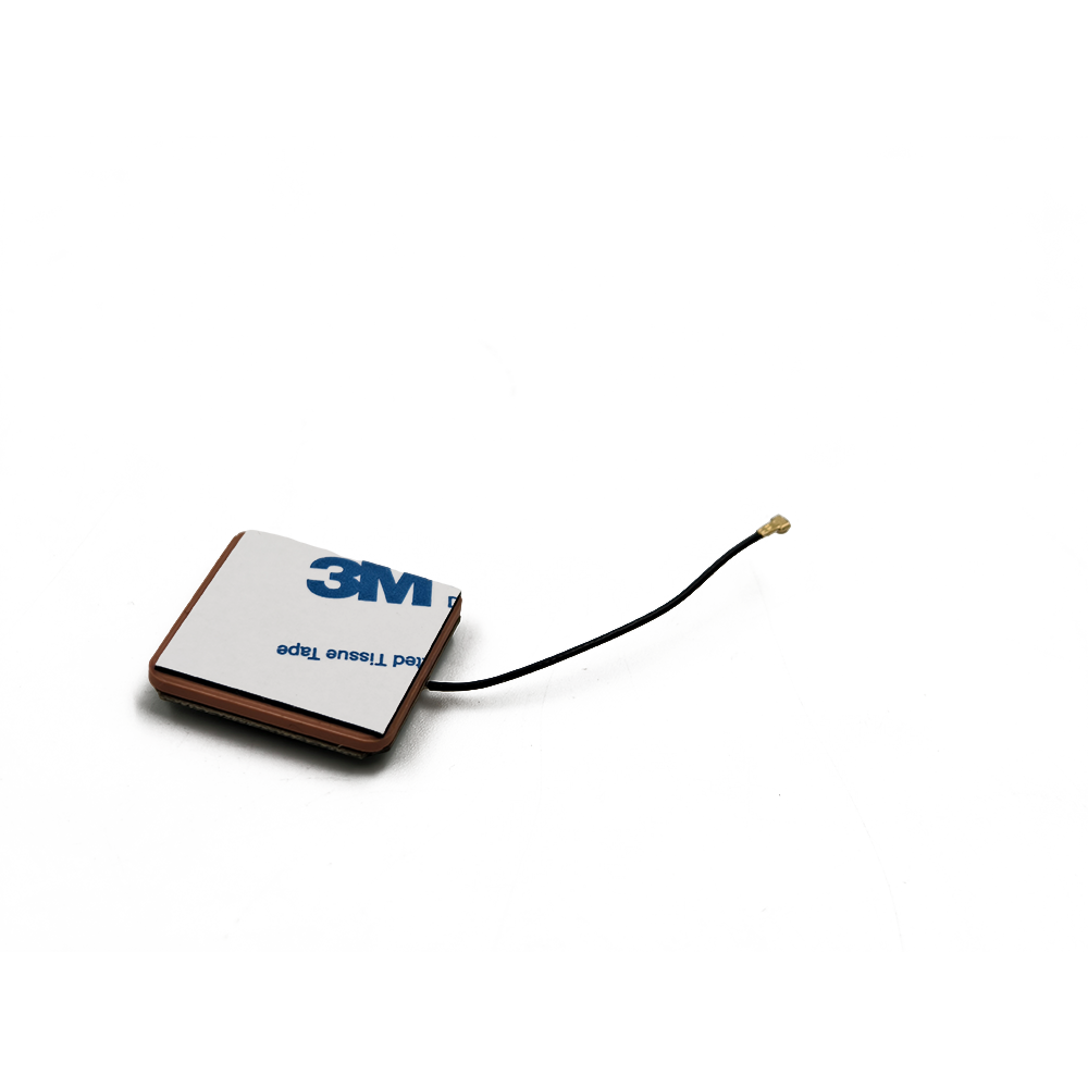
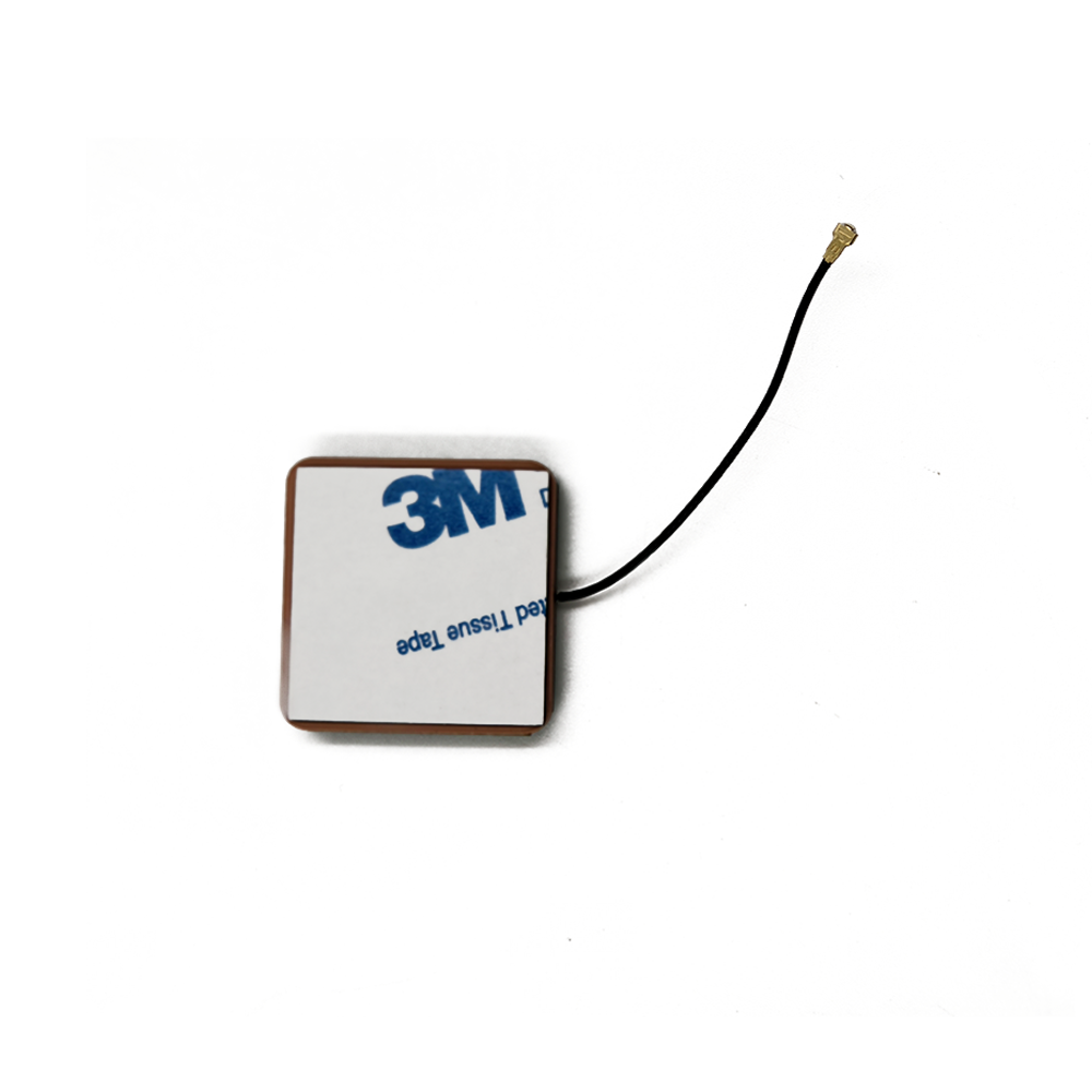
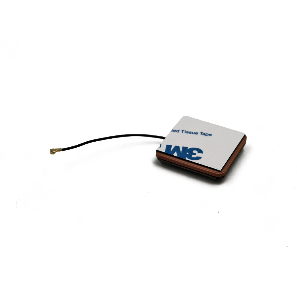
A patch antenna, also known as a microstrip antenna, is characterized by its flat, planar structure. The integrated ceramic RTK patch antenna typically consists of a flat conductive patch, often made of metals like copper or gold, printed on a ceramic dielectric substrate. The ceramic substrate, with its unique material properties, plays a pivotal role in the antenna's performance. Below the dielectric substrate lies a ground plane, which is essential for the proper functioning of the antenna. The conductive patch, dielectric substrate, and ground plane together form the basic structure of the antenna. The size and shape of the conductive patch can vary; common shapes include rectangular, circular, and square. Each shape has its own implications for the antenna's radiation characteristics and resonant frequency.
1.2 Significance in Modern Technology
The significance of integrated ceramic RTK patch antennas in modern technology cannot be overstated. In the field of surveying and mapping, these antennas enable highly accurate measurements, reducing errors that were common with traditional positioning methods. For example, in large - scale construction projects, the use of RTK - enabled devices with ceramic patch antennas can ensure that the layout of buildings and infrastructure is precisely aligned, saving both time and resources.
In the realm of autonomous vehicles, accurate positioning is a matter of safety. Integrated ceramic RTK patch antennas provide the high - precision location data required for self - driving cars to navigate safely on roads, avoiding collisions and making correct decisions at intersections. In precision agriculture, farmers can use RTK - equipped drones or tractors with these antennas to precisely apply fertilizers and pesticides, optimizing crop yields while minimizing environmental impact.
The design and construction of integrated ceramic RTK patch antennas are intricate processes that require careful consideration of multiple factors to ensure optimal performance.
2.1 Design Considerations
2.1.1 Frequency Band Selection
The choice of frequency band is a fundamental design consideration. Different applications demand different frequency bands. For example, in GPS - based positioning, the L1 band (around 1575.42 MHz) is commonly used for general navigation, while the L2 band (around 1227.60 MHz) and L5 band (around 1176.45 MHz) are used for more precise positioning applications. The antenna must be designed to operate efficiently within the selected frequency band or bands. The dimensions of the antenna, particularly the size of the conductive patch, are directly related to the operating frequency. As a general rule, the larger the patch, the lower the resonant frequency. For a rectangular patch antenna, the length \(L\) and width \(W\) can be calculated using the following approximate formulas for a given frequency \(f\) and the dielectric constant \(\epsilon_r\) of the substrate:
\(L=\frac{c}{2f\sqrt{\epsilon_{reff}}}\)
\(W=\frac{c}{2f\sqrt{\frac{\epsilon_{r}+1}{2}}}\)
where \(c\) is the speed of light in free - space and \(\epsilon_{reff}\) is the effective dielectric constant of the substrate, which takes into account the fringing fields at the edges of the patch.
2.1.2 Dielectric Substrate Properties
The properties of the ceramic dielectric substrate are critical to the antenna's performance. Ceramic materials are preferred due to their high dielectric constants (\(\epsilon_r\)) and low loss tangents (\(\tan\delta\)). A high dielectric constant allows for a more compact antenna design. For example, if the dielectric constant of the substrate is increased, the size of the antenna can be reduced while maintaining the same resonant frequency. However, a high dielectric constant also has some drawbacks, such as a decrease in the antenna's bandwidth. The loss tangent of the substrate determines the amount of energy that is dissipated as heat within the substrate. A low loss tangent is desirable to minimize power losses and improve the antenna's efficiency. Materials like alumina (\(Al_2O_3\)) and barium titanate (\(BaTiO_3\)) are commonly used as ceramic substrates in patch antennas due to their favorable dielectric properties.
2.1.3 Feed Mechanism
The feed mechanism is responsible for injecting the radio - frequency (RF) signal into the antenna. There are several types of feed mechanisms, with the microstrip line feed and coaxial feed being the most common. In a microstrip line feed, a narrow strip of conductive material is printed on the same side as the radiating patch and is connected to the patch at a specific point. The location of the feed point on the patch can significantly affect the antenna's impedance and radiation pattern. If the feed point is at the center of the patch, the antenna will have a balanced radiation pattern. However, if the feed point is offset, the antenna can be made to have a more directional radiation pattern. A coaxial feed, on the other hand, consists of an inner conductor that penetrates the dielectric substrate and is connected to the patch, while the outer conductor is connected to the ground plane. Coaxial feeds are often used when a more isolated and stable feed connection is required.
2.2 Construction Process
2.2.1 Fabrication of the Conductive Patch
The conductive patch is typically fabricated using photolithography techniques. First, a thin layer of metal, such as copper, is deposited on the surface of the ceramic dielectric substrate. This can be done through methods like sputtering or electrodeposition. Then, a photoresist layer is applied on top of the metal layer. A mask with the desired pattern of the conductive patch is placed over the photoresist, and ultraviolet light is used to expose the photoresist. The exposed areas of the photoresist are then developed, leaving behind the pattern of the conductive patch. The unprotected metal areas are etched away using a chemical etchant, resulting in the formation of the conductive patch with the desired shape and dimensions.
2.2.2 Assembly with the Ground Plane
After the fabrication of the conductive patch, the next step is to assemble the antenna with the ground plane. The ground plane is usually made of a metal sheet, such as copper or aluminum. The ceramic substrate with the conductive patch is carefully aligned and attached to the ground plane. This can be done using adhesives or mechanical fasteners. The distance between the conductive patch and the ground plane, which is determined by the thickness of the dielectric substrate, is crucial for the antenna's performance. A proper alignment ensures that the electromagnetic fields are properly confined and radiated, resulting in an efficient antenna.
2.2.3 Integration of Additional Components (if applicable)
In some cases, additional components may be integrated into the antenna design. For example, in active antennas, a low - noise amplifier (LNA) may be added to boost the weak received signals. The LNA is usually mounted on the same substrate as the antenna or in close proximity to it. Filters may also be integrated to remove unwanted frequencies and improve the signal - to - noise ratio. The integration of these components requires careful consideration of their electrical and physical compatibility with the antenna structure to avoid any negative impacts on the antenna's performance.
The operation of integrated ceramic RTK patch antennas is based on the principles of electromagnetic wave propagation and radiation.
3.1 Electromagnetic Wave Propagation in the Antenna Structure
When an RF signal is applied to the feed point of the antenna, an electric current is induced in the conductive patch. This current generates an electromagnetic field around the patch. The ceramic dielectric substrate, with its high dielectric constant, confines and guides the electromagnetic field. The electromagnetic wave propagates within the structure formed by the conductive patch, dielectric substrate, and ground plane.
The propagation of the electromagnetic wave in the dielectric substrate is different from that in free - space. The speed of the electromagnetic wave in the substrate is slower than in free - space, and its wavelength is shorter. The effective dielectric constant of the substrate affects the propagation characteristics of the wave. The fringing fields at the edges of the conductive patch also play an important role in the radiation process. These fringing fields extend beyond the physical boundaries of the patch and interact with the surrounding space, contributing to the radiation of the antenna.
3.2 Radiation Mechanism
The radiation of the integrated ceramic RTK patch antenna occurs due to the interaction of the electromagnetic fields with the surrounding space. The conductive patch acts as a radiator. When the RF current flows through the patch, it creates oscillating electric and magnetic fields. These fields are perpendicular to each other and to the direction of propagation of the electromagnetic wave.
The fringing fields at the edges of the patch are responsible for the primary radiation. As the electromagnetic wave reaches the edges of the patch, the fringing fields extend into the air, causing the antenna to radiate energy. The radiation pattern of the antenna, which describes the distribution of radiated power in different directions, is determined by the shape and size of the conductive patch, the properties of the dielectric substrate, and the feed mechanism. For example, a rectangular patch antenna typically has a broadside radiation pattern, meaning that it radiates most of its energy in a direction perpendicular to the plane of the patch.
3.3 Interaction with RTK Technology
In RTK technology, the integrated ceramic patch antenna plays a vital role in receiving satellite signals. The antenna receives signals from multiple satellites in the Global Navigation Satellite System (GNSS), such as GPS, GLONASS, Galileo, and BeiDou. These signals contain information about the satellite's position and the time of transmission.
The RTK system works by comparing the signals received by a base station, which has a known location, with the signals received by a rover station, which is the device whose position needs to be determined. The difference in the signals, known as the carrier - phase difference, is used to calculate the precise position of the rover. The high - precision reception capabilities of the integrated ceramic RTK patch antenna are crucial for accurately measuring these carrier - phase differences. The antenna's ability to receive signals from multiple satellites simultaneously and its low noise characteristics enable the RTK system to achieve centimeter - level positioning accuracy.
Integrated ceramic RTK patch antennas offer several advantages that make them popular in various applications. However, like any technology, they also face certain challenges.
4.1 Advantages
4.1.1 High Precision Positioning
One of the most significant advantages of integrated ceramic RTK patch antennas is their ability to enable high - precision positioning. In applications such as surveying and autonomous vehicles, the centimeter - level accuracy provided by these antennas is essential. The use of multiple frequency bands, as supported by many of these antennas, allows for the elimination of errors caused by ionospheric and tropospheric delays. By receiving signals from different satellites and analyzing the phase differences between them, the RTK system can accurately calculate the position of the receiver. For example, in a construction project where the alignment of a large bridge is being surveyed, the high - precision positioning provided by the integrated ceramic RTK patch antenna ensures that the bridge components are installed with utmost accuracy, reducing the risk of structural failures in the future.
4.1.2 Compact Size and Lightweight
The use of ceramic materials in the antenna design allows for a compact and lightweight structure. Ceramic materials have a high dielectric constant, which enables the reduction of the antenna's size without sacrificing performance. This compactness and lightweight nature make these antennas ideal for applications where space and weight are critical factors, such as in drones and wearable devices. In a drone used for aerial mapping, a compact and lightweight integrated ceramic RTK patch antenna can be easily integrated into the drone's structure without adding significant weight, which would otherwise affect the drone's flight performance and battery life.
4.1.3 Low Power Consumption
Integrated ceramic RTK patch antennas generally have low power consumption. The efficient design of the antenna, along with the properties of the ceramic substrate, allows for the reception and transmission of signals with minimal power requirements. This is beneficial for battery - powered devices, as it helps to extend the device's battery life. For example, in a handheld GNSS receiver used by hikers for navigation, the low power consumption of the integrated ceramic RTK patch antenna ensures that the device can operate for longer periods without the need for frequent battery replacements or recharges.
4.1.4 Durability and Stability
Ceramic materials are known for their durability and stability. They can withstand harsh environmental conditions, including temperature variations, humidity, and mechanical stress. In outdoor applications, such as in agricultural fields or construction sites, the integrated ceramic RTK patch antennas can maintain their performance over long periods. The stability of the ceramic substrate also contributes to the consistent performance of the antenna, ensuring that the positioning accuracy remains high even in challenging environments.
4.2 Challenges
4.2.1 Narrow Bandwidth
One of the main challenges with integrated ceramic RTK patch antennas is their relatively narrow bandwidth. The high dielectric constant of the ceramic substrate, which is advantageous for reducing the antenna's size, also contributes to a narrow bandwidth. A narrow bandwidth means that the antenna can only operate efficiently within a limited frequency range. This can be a problem in applications where a wide range of frequencies need to be covered, such as in multi - band GNSS receivers. To overcome this challenge, antenna designers often use techniques such as antenna stacking or the use of complex feed networks to increase the bandwidth. However, these techniques can increase the complexity and cost of the antenna design.
4.2.2 Sensitivity to Environmental Factors
Although ceramic materials are durable, the performance of integrated ceramic RTK patch antennas can still be affected by environmental factors. For example, extreme temperatures can cause the dielectric constant of the ceramic substrate to change, which in turn can affect the antenna's resonant frequency and radiation pattern. Humidity can also have an impact on the antenna's performance, especially if water droplets accumulate on the surface of the antenna. In addition, electromagnetic interference from nearby electronic devices or power lines can disrupt the signals received by the antenna. To mitigate these effects, antenna designers may need to incorporate additional shielding or compensation mechanisms into the antenna design.
4.2.3 Complex Design and Manufacturing Process
The design and manufacturing of integrated ceramic RTK patch antennas are complex processes. The precise control of the antenna's dimensions, the selection of the right ceramic material, and the integration of additional components require advanced manufacturing techniques and expertise. Any small deviation in the manufacturing process can lead to significant changes in the antenna's performance. For example, a slight variation in the thickness of the dielectric substrate can affect the antenna's resonant frequency and impedance. The complexity of the design and manufacturing process also contributes to the relatively high cost of these antennas, which may limit their adoption in some cost - sensitive applications.
Integrated ceramic RTK patch antennas have a wide range of applications across various industries, and ongoing research and development are shaping their future trends.
5.1 Current Applications
5.1.1 Surveying and Mapping
In the field of surveying and mapping, integrated ceramic RTK patch antennas are widely used. Land surveyors rely on these antennas to accurately measure property boundaries, create topographic maps, and monitor land subsidence. The high - precision positioning capabilities of the antennas allow for the collection of highly accurate data, which is essential for urban planning, infrastructure development, and environmental monitoring. For example, in a large - scale urban development project, surveyors use RTK - equipped devices with integrated ceramic patch antennas to precisely mark the locations of new buildings, roads, and utility lines, ensuring that the development adheres to the planned design.
5.1.2 Autonomous Vehicles
Autonomous vehicles heavily depend on accurate positioning systems, and integrated ceramic RTK patch antennas play a crucial role in this regard. These antennas provide the centimeter - level accuracy required for self - driving cars to navigate safely on roads. By receiving signals from multiple satellites and processing the data in real - time, the vehicle's onboard computer can determine its exact position, allowing it to make informed decisions such as when to accelerate, brake, or turn. In addition, the compact size and low power consumption of the antennas make them suitable for integration into the vehicle's existing electronics system without adding significant weight or complexity.
5.1.3 Precision Agriculture
Precision agriculture is another area where integrated ceramic RTK patch antennas find extensive use. Farmers use RTK - enabled tractors, drones, and other agricultural equipment to precisely apply fertilizers, pesticides, and water. The high - precision positioning provided by the antennas allows farmers to target specific areas of the field, reducing the waste of resources and minimizing environmental impact. For example, a drone equipped with an integrated ceramic RTK patch antenna can be used to map the nutrient levels in a field and then precisely apply fertilizers only to the areas that need them, resulting in improved crop yields and reduced costs.
5.1.4 Maritime and Aerial Navigation
In maritime and aerial navigation, accurate positioning is essential for safety. Integrated ceramic RTK patch antennas are used in ships, boats, aircraft, and unmanned aerial vehicles (UAVs) to provide precise location information. In shipping, these antennas help vessels navigate through narrow channels, avoid collisions with other ships and obstacles, and dock safely at ports. In aviation, they assist aircraft in landing accurately, especially in low - visibility conditions. The durability and stability of the antennas make them suitable for use in harsh maritime and aerial environments.
5.2 Future Trends
5.2.1 Multi - Band and Multi - System Integration
As the demand for more accurate and reliable positioning increases, future integrated ceramic RTK patch antennas are likely to see further advancements in multi - band and multi - system integration. Currently, most antennas support multiple GNSS systems such as GPS, GLONASS, Galileo, and BeiDou. However, future designs may be able to receive signals from additional satellite systems and cover a wider range of frequency bands. This will improve the positioning accuracy and availability, especially in challenging environments where signals from some systems may be blocked. For example, in urban canyons or dense forests, the ability to receive signals from multiple systems and bands will increase the chances of obtaining a reliable position fix.
5.2.2 Miniaturization and Integration with Other Devices
The trend towards miniaturization will continue, with integrated ceramic RTK patch antennas becoming even smaller and more integratedinto other electronic devices. The development of advanced microfabrication technologies, such as 3D printing and nanoimprint lithography, will enable the production of antennas with even smaller dimensions. For instance, 3D printing allows for the creation of complex, three - dimensional antenna structures that can be tailored to fit into the tight spaces of modern electronic devices, such as smartphones and wearable health monitors.
Moreover, the integration of integrated ceramic RTK patch antennas with other components, such as sensors and processors, will become more seamless. This integration will result in the development of highly compact and multifunctional systems. For example, a wearable device for outdoor adventurers could combine an integrated ceramic RTK patch antenna for positioning with a heart - rate sensor and a temperature sensor. All these components would be integrated into a single, small - sized device, providing adventurers with real - time location data along with vital health and environmental information.
5.2.3 Enhanced Antenna Performance through Intelligent Design
Future integrated ceramic RTK patch antennas will also benefit from intelligent design approaches. With the advancement of artificial intelligence (AI) and machine learning (ML) technologies, antenna designers can use these tools to optimize the antenna's performance. AI - based design algorithms can simulate and analyze a large number of antenna design parameters, such as the shape of the conductive patch, the properties of the dielectric substrate, and the feed mechanism, to find the optimal combination that maximizes the antenna's performance metrics, such as gain, bandwidth, and efficiency.
For example, an ML model can be trained on a large dataset of antenna performance data. Once trained, the model can quickly predict the performance of a new antenna design based on its parameters, allowing designers to iterate through different designs more efficiently. Additionally, adaptive antennas that can adjust their radiation patterns and operating frequencies in real - time based on the surrounding environment will become more common. These adaptive antennas will use AI algorithms to detect changes in the signal environment, such as the presence of electromagnetic interference or the blockage of satellite signals, and adjust their parameters accordingly to maintain optimal performance.
5.2.4 Development of New Ceramic Materials
The exploration and development of new ceramic materials will be a key trend in the future of integrated ceramic RTK patch antennas. Researchers are constantly looking for ceramic materials with improved properties, such as higher dielectric constants, lower loss tangents, and better thermal stability. For example, some new ceramic composites are being developed that combine the high dielectric constant of ceramic materials with the flexibility of polymers. These composite materials offer the advantage of being more flexible than traditional ceramic materials, making them suitable for use in flexible electronic devices, such as foldable smartphones and wearable devices.
Another area of research is the development of ceramic materials with tunable dielectric properties. These materials allow the dielectric constant of the substrate to be adjusted dynamically, which in turn allows the antenna's resonant frequency to be tuned. This tunability is particularly useful in multi - band applications, as it enables the antenna to switch between different frequency bands without the need for complex feed networks or multiple antennas. For example, a tunable ceramic substrate could allow an integrated ceramic RTK patch antenna to operate in both the GPS L1 band and the Galileo E1 band (around 1575.42 MHz), simply by adjusting the dielectric constant of the substrate.
Conclusion
The integrated ceramic RTK patch antenna has established itself as a vital component in modern positioning and communication systems, offering a unique combination of high - precision positioning, compact size, low power consumption, and durability. Throughout this comprehensive overview, we have explored the various aspects of these antennas, from their basic definition and structure to their intricate design and construction processes, their underlying working principles, their numerous advantages and the challenges they face, their wide - ranging applications, and the promising future trends that will shape their development.
In terms of their structure and design, the integration of ceramic materials into patch antennas has been a game - changer. The high dielectric constant of ceramic substrates allows for the miniaturization of the antenna without compromising on performance, while their low loss tangents ensure efficient signal transmission and reception. The careful selection of frequency bands, the design of appropriate feed mechanisms, and the precise fabrication of the conductive patch and ground plane are all critical factors that contribute to the optimal performance of these antennas.
The working principles of integrated ceramic RTK patch antennas, based on electromagnetic wave propagation and radiation, highlight the importance of the interaction between the conductive patch, dielectric substrate, and ground plane. The ability of these antennas to receive satellite signals and interact with RTK technology enables the achievement of centimeter - level positioning accuracy, which is essential in applications such as surveying and mapping, autonomous vehicles, precision agriculture, and maritime and aerial navigation.
While the advantages of integrated ceramic RTK patch antennas are significant, including their high precision, compact size, low power consumption, and durability, they also face challenges such as narrow bandwidth, sensitivity to environmental factors, and complex design and manufacturing processes. However, ongoing research and development efforts are addressing these challenges, with techniques such as antenna stacking, the use of adaptive algorithms, and the development of new ceramic materials showing great promise in overcoming these limitations.
Looking towards the future, the integrated ceramic RTK patch antenna is poised for further growth and innovation. The trends of multi - band and multi - system integration, miniaturization and integration with other devices, enhanced performance through intelligent design, and the development of new ceramic materials will all contribute to the continued advancement of these antennas. These developments will expand their applications even further, making them an even more integral part of future technological systems.
In conclusion, the integrated ceramic RTK patch antenna has come a long way in a relatively short period, and its importance in modern technology will only continue to grow. As the demand for high - precision positioning and reliable communication increases in various industries, these antennas will play a crucial role in meeting these demands, driving innovation and progress in fields such as autonomous transportation, precision agriculture, and environmental monitoring. With ongoing research and development, the future of integrated ceramic RTK patch antennas is bright, and we can expect to see even more advanced and versatile designs in the years to come.

 86 0755 2819 9597
Lucy Yang | lucy.y@toxutech.com
Nicole Li | nicole@toxutech.com
Dotty Zhao | sales04@toxutech.com
Global Business Director / Sales Team / Global Operations


 En
En Cn
Cn Korean
 Home >


