

-
Products -PCBA Manufacturing RF Connectors RF Cable Assemblys Embedded Antennas External Antennas Positioning Chips and Modules
RF Connectors

RF Cable Assemblys
Embedded Antennas
External Antennas
Positioning Chips and Modules


 Language


Language


In the intricate ecosystem of high-precision GNSS, achieving real-time centimeter-level accuracy is not the feat of a single device but the result of a perfectly synchronized chain of components. The High-Gain RTK Antenna is the first and most critical link in this chain, but its performance is wholly dependent on a concept often overlooked: compatibility. A high-gain RTK antenna's compatibility is not a simple matter of connector types; it is a complex interplay of electromagnetic characteristics, signal processing requirements, and physical integration that determines the success or failure of an entire RTK system.
A high-gain RTK antenna compatible system refers to the seamless integration of three core components:
The Antenna itself: Designed for high gain, stable phase center, and superior multipath rejection.
The GNSS Receiver: The engine that processes the signals, resolves integer ambiguities, and computes position.
The System Workflow: This includes the physical setup (base and rover), the data link, and the processing software.
True compatibility ensures that these elements work in concert to deliver the promised accuracy. It means that the pristine signal captured by the antenna is translated faithfully into a precise positional solution by the receiver, and that this data is usable within the user's specific application, whether it's guiding an autonomous tractor or monitoring a dam's structural integrity.
The importance of compatibility is paramount because RTK is a differential technique. It relies on the correlation of errors between a base station and a rover. For these errors to cancel out effectively, the measurements from both ends must be based on a consistent and well-understood reference point. The antenna's phase center is this reference point. If the base and rover antennas have different phase center characteristics, or if the receiver does not correctly account for them, a systematic bias is introduced into the solution. This bias can prevent the receiver from achieving a "fixed" integer solution altogether, or worse, can result in a precise but inaccurate fix, which is far more dangerous than a outright failure.
Furthermore, compatibility extends beyond the base-rover pair. It encompasses the antenna's ability to function with different receiver brands, its performance across multiple satellite constellations and frequencies, its resilience to the local RF environment, and its physical suitability for the intended platform. A antenna might be technically superb but incompatible if its calibration data is not supported by the user's software, if its connector is wrong for the field environment, or if its power requirements cannot be met by the receiver.
Therefore, selecting a "high-gain RTK antenna" is not enough. One must select a "compatible high-gain RTK antenna"—a component whose electrical, physical, and operational parameters are in perfect alignment with the rest of the system. This overview establishes that compatibility is not a feature but a fundamental requirement, the absence of which renders even the most advanced antenna ineffective. It is the golden thread that ties the system together, ensuring that the immense potential of high-precision GNSS is fully realized in practice.
The design and construction of a high-gain RTK antenna are not undertaken in isolation. Every aspect is meticulously engineered not only for standalone performance but, crucially, for compatibility within a broader ecosystem of receivers, software, and applications. This involves a deliberate focus on standardization, stability, and the provision of essential data for downstream processing.
1. The Radiating Element: Stability Above All
The heart of the antenna is a patched element, typically in a stacked configuration for multi-band operation (L1, L2, L5). For compatibility, the design prioritizes one key metric: Phase Center Stability.
Symmetrical Design: The patch, its feed points, and the surrounding ground plane are designed to be perfectly symmetrical. This minimizes Phase Center Variation (PCV)—the movement of the electrical phase center with the elevation and azimuth of the incoming satellite signal. A stable phase center ensures that measurements are consistent, which is the bedrock of differential positioning.
Multi-Frequency Integrity: The antenna must perform consistently across all supported bands. The phase center for the L1 band should be co-located as closely as possible with that of the L2 and L5 bands. This ensures that observations from different frequencies are coherent and can be used together for advanced error correction (e.g., ionospheric modeling) without introducing bias.
2. The Choke Ring: Consistent Multipath Rejection
The inclusion of a choke ring is a primary differentiator for high-gain RTK antennas. Its design is optimized for compatibility.
Predictable Performance: The depth and spacing of the rings are calculated to provide effective multipath rejection across the entire GNSS spectrum. This provides a consistent and predictable error environment. A compatible antenna delivers a known, low level of multipath error that the RTK engine can reliably account for, as opposed to a highly variable multipath environment that can disrupt the integer ambiguity resolution process.
3. The Low-Noise Amplifier (LNA): A Balanced Boost
The integrated LNA is designed for transparent integration.
Gain and Linearity: The gain must be high enough to overcome cable losses but not so high that it saturates the receiver's front-end when strong out-of-band signals are present. Its response must be linear across the entire dynamic range of GNSS signals to avoid distorting the signals and corrupting the phase measurements.
Standard Power Requirements: The antenna must operate within the standard power range provided by most GNSS receivers via the coaxial cable (typically 3-5V DC). A non-standard voltage requirement would immediately render the antenna incompatible with a large segment of the receiver market.
4. Calibration: The Key to Digital Compatibility
This is the single most important aspect of construction for compatibility. An antenna is not truly compatible without it.
Absolute Calibration: The antenna undergoes rigorous testing in an anechoic chamber. This process maps the precise Phase Center Offset (PCO) and Phase Center Variation (PCV) for every frequency band it supports.
The ANTEX File: This calibration data is published in a standardized industry format called an ANTEX (ANTenna EXchange) file. This file contains the PCO (a 3D vector from the Antenna Reference Point) and a table of PCV values for different frequencies and elevation/azimuth angles. The provision of an ANTEX file is what transforms a physical antenna into a calibrated instrument that can be used interoperably.
5. Connectors and Sealing: Physical Compatibility
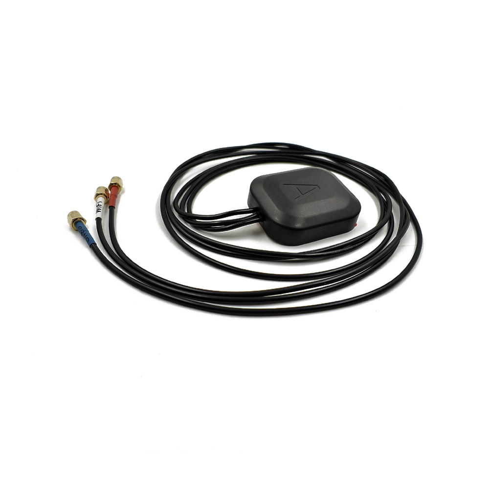
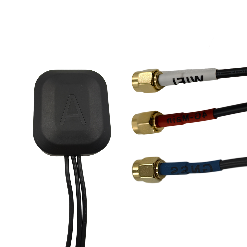
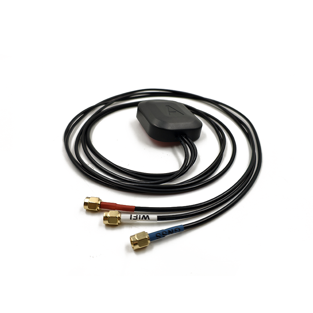
Standardized Connectors: The antenna must feature standard RF connectors (e.g., TNC, N-type) that match the cables and receptacles used in the industry. A proprietary connector creates an immediate physical incompatibility.
Environmental Sealing: The antenna must be ruggedized (IP67 or higher) to ensure reliable operation in the field. An antenna that fails due to moisture ingress is, by definition, incompatible with outdoor use.
6. Mounting System
A standard mounting thread (e.g., 5/8"-11) allows the antenna to be installed on a wide array of tripods, poles, and permanent monuments, ensuring physical compatibility with existing geodetic infrastructure.
In summary, the construction of a compatible high-gain RTK antenna is a process of building predictability and standardization into the hardware. It is engineered to be a known, stable, and well-characterized component that can be dropped into any standards-compliant RTK system and perform as expected, enabling true plug-and-play precision.
The operation of a high-gain RTK antenna and its subsequent compatibility with a receiver is a detailed process of signal conditioning, standardization, and data provision. Its working principles are what allow it to function as a seamless component within a larger, complex system.
1. Delivering a Pristine, Predictable Signal
The antenna's primary job is to provide the receiver with the cleanest possible signal.
High Gain and Low Noise: The integrated LNA boosts the extremely weak satellite signals, ensuring they are strong enough to survive the journey down the transmission cable. Crucially, it does this with minimal added noise (low noise figure), preserving the signal-to-noise ratio (SNR). A high SNR is essential for the receiver to maintain a stable lock on the carrier phase, a prerequisite for RTK.
Multipath Suppression: The choke ring structure actively suppresses multipath signals by creating a high-impedance barrier to low-angle reflections. This provides the receiver with a signal dataset that is dominated by direct line-of-sight observations, simplifying its correlation and error-correction tasks.
2. Establishing a Stable Electrical Reference Point
The core of RTK compatibility lies in the concept of the phase center. The antenna's design ensures that this point is stable.
A Rock-Solid Origin: Through symmetrical design and stable materials, the antenna ensures that the electrical path length from the satellite to the antenna's phase center is consistent, regardless of the satellite's position in the sky or the ambient temperature.
The Role of Calibration: The ANTEX file provided by the manufacturer is a model of the antenna's behavior. It tells the receiver's software: "If you measure the signal at the physical connector, the true measurement actually originated from this specific point in space (the PCO), and here is how to correct for any tiny variations (the PCV)."
3. The Handshake with the Receiver
Compatibility is achieved in the digital handshake between the antenna's calibration data and the receiver's firmware.
Measurement: The antenna captures the satellite signal, and the receiver makes a raw phase measurement.
Correction: The receiver's processor applies the corrections from the ANTEX file to this raw measurement. It effectively "moves" the measurement from the physical feed point to the calibrated, stable phase center.
Differential Processing: In an RTK system, both the base and rover receivers perform this correction using their respective antenna models. Because both are now referencing their measurements to a known, stable point (their own calibrated phase center), the common errors in the satellite signals (orbit, clock, atmosphere) become highly correlated and can be differenced away, allowing the integer ambiguities to be resolved.
4. Multi-Constellation and Multi-Frequency Support
A compatible antenna works seamlessly with all signals from all constellations.
The Receiver's Role: The receiver is responsible for acquiring and tracking signals from GPS, GLONASS, Galileo, and BeiDou. The antenna's job is to provide a wide enough bandwidth and stable enough phase response across all these frequencies (L1, L2, L5, etc.) so that the receiver can do its job effectively.
Interoperability: This allows a user to mix and match receivers from different manufacturers, as long as each receiver has access to the correct ANTEX files for its antenna. This is the essence of system-level compatibility.
5. Providing Power and Handling Data
The antenna draws power from the receiver through the coaxial cable. A compatible antenna operates within the standard voltage and current limits, ensuring it does not overload the receiver's power supply. The signal it returns is a pure analog RF signal; all processing is done by the receiver, making the interface simple and standardized.
In essence, the antenna works by being a predictable and well-characterized source of data. It doesn't process information; it provides high-fidelity raw materials (the signals) along with a detailed instruction manual (the calibration data) that allows the receiver—the brain of the operation—to produce a perfectly accurate solution.
Utilizing a properly compatible high-gain RTK antenna system offers profound advantages for achieving reliable precision. However, ensuring this compatibility introduces a set of challenges that must be meticulously managed by system integrators and end-users.
Advantages:
Plug-and-Play Precision: The primary advantage of a compatible system is the ability to achieve optimal performance without extensive, guesswork-dependent tuning. When a calibrated antenna is paired with a receiver that supports its model, the system "just works," delivering rapid fixed solutions and high accuracy right out of the box.
Interoperability between Brands: The standardized ANTEX format allows for mixing and matching components. A user can employ a high-quality antenna from Manufacturer A with a receiver from Manufacturer B, as long as the receiver's software library includes Manufacturer A's ANTEX file. This prevents vendor lock-in and allows users to select best-in-class components for each part of their system.
Reduced Systematic Errors: The application of precise phase center corrections eliminates a significant source of systematic error. This leads to more accurate absolute positioning, which is critical for applications like monitoring, where the absolute movement of a structure is being measured over time, not just its relative position.
Improved Reliability and Fix Rate: By providing a clean signal and stable reference point, a compatible antenna helps the RTK engine resolve integer ambiguities faster and maintain a fixed solution more reliably, even in moderately challenging environments. It reduces the occurrences of "fix hopping" or outright loss of lock.
Data Integrity and Reproducibility: For scientific applications, using calibrated antennas ensures that data collected is traceable and reproducible. Different teams using different equipment can compare results with confidence if they are all using properly calibrated components.
Challenges:
The Calibration Awareness Challenge: The biggest challenge is user awareness and implementation. An antenna's calibration is useless if the user is unaware of it, cannot find the ANTEX file, or does not know how to load it into their receiver's configuration software. This is a common source of performance degradation.
Management of ANTEX Files: Receiver manufacturers must maintain extensive and up-to-date libraries of ANTEX files for hundreds of antenna models. If a newly purchased antenna model is not in a receiver's built-in library, the user must manually locate and upload the file, adding a layer of complexity.
Mismatched Base and Rover Antennas: Using different antenna models on the base and rover is a major compatibility pitfall. If the phase center characteristics of the two antennas are not identical, and their respective corrections are not applied, a residual bias will remain in the differential solution, degrading accuracy. The best practice is to use the same antenna model at both ends.
Cost and Complexity: High-gain antennas with rigorous calibration are more expensive to design, test, and manufacture. This cost is passed on to the end-user, making a fully compatible system a significant investment.
Verification Difficulty: For most users, it is nearly impossible to independently verify that the phase center corrections are being applied correctly. They must trust the receiver's firmware and their own configuration. This lack of visibility can make troubleshooting difficult.
Physical and Electrical Compatibility: Even with perfect calibration, physical issues can create incompatibility: incorrect connectors, insufficient power from the receiver, or cable faults can all prevent the system from functioning.
In conclusion, the advantages of a compatible system are transformative for achieving reliable, high-precision results. However, these benefits are contingent upon successfully navigating the challenges of calibration management, system design, and user education. The "magic" of compatibility only works when the entire signal chain is correctly configured and aligned.
The value of a high-gain RTK antenna compatible system is proven in fields where data integrity, reliability, and absolute accuracy are directly tied to operational success, safety, and scientific validity.
Applications:
National and Regional CORS Networks: These networks rely on identical, calibrated antennas at all reference stations to ensure the correction data they generate is consistent and unbiased across the entire coverage area. Compatibility is the foundation of the network's integrity.
Precision Agriculture: Autonomous guidance systems for tractors and harvesters depend on reliable, continuous RTK fixes. Using compatible, calibrated antennas on both the base station and the machinery ensures sub-inch pass-to-pass accuracy, minimizing overlaps and skips, which saves inputs and boosts yields.
Critical Infrastructure Monitoring: Monitoring the movement of dams, bridges, and railways requires detecting millimeter-level deformations over years. Using calibrated antennas is non-negotiable here, as it eliminates antenna-specific biases that could be mistaken for actual structural movement.
Geodetic Surveying: For high-precision control surveys and scientific applications like tectonic plate monitoring, the use of calibrated antennas is a standard requirement. It ensures that measurements are scientifically rigorous and can be compared with historical data and data from other research groups.
Construction and Machine Control: Grade control systems on bulldozers and excavators require robust performance in electrically noisy and multipath-prone environments. A compatible high-gain antenna system provides the reliability needed to maintain accuracy throughout the project, ensuring that designs are built to spec.
Unmanned Aerial Vehicle (UAV) Mapping: When using a drone for photogrammetry or LiDAR, the ground base station must use a calibrated antenna. This ensures that the precise position of the base is known, which in turn allows the drone's camera positions to be accurately calculated, creating highly accurate maps without ground control points.
Future Trends:
Automated Calibration Handling: Future receivers and processing software will feature automated calibration discovery. The antenna could have a small EEPROM chip storing its unique serial number and calibration data, which the receiver would automatically read and apply, eliminating user error entirely.
On-the-Fly Calibration and Integrity Monitoring: Advanced systems could continuously monitor the performance of the antenna-receiver pair and make tiny, real-time adjustments to the applied corrections, accounting for aging or minor physical damage.
Tighter Integration with PPP-RTK: As Precise Point Positioning with RTK corrections becomes more widespread, the demand for ultra-stable, well-calibrated antennas will grow. PPP-RTK is highly sensitive to unmodeled errors, making antenna compatibility even more critical.
Cloud-Based Calibration Libraries: Instead of being stored on the receiver, ANTEX files could be stored in the cloud. The receiver would simply transmit the antenna model and serial number via a cellular connection and automatically download the latest calibration parameters.
Multi-Antenna Systems and Array Processing: Future systems may use multiple antennas on a single platform (e.g., a car or drone) to instantly resolve integer ambiguities and calculate heading. Ensuring phase compatibility between all antennas in the array will be a critical design challenge.
Enhanced Resilience Features: Compatibility will also encompass resilience to jamming and spoofing. Antennas may incorporate built-in interference detection and filtering capabilities that are seamlessly integrated with the receiver's mitigation algorithms.
The future of high-gain RTK antenna compatibility is one of greater intelligence, automation, and integration, moving from a static configuration to a dynamic, self-optimizing system that ensures precision is both effortless and guaranteed.
Conclusion
The journey to centimeter-level accuracy is a complex one, fraught with potential sources of error. The high-gain RTK antenna is the sentinel at the gate, tasked with capturing the faint signals from space with utmost fidelity. However, its true value is only unlocked through compatibility—the seamless, standards-based integration of its calibrated performance with the processing power of the GNSS receiver.
Compatibility is the bedrock upon which trustworthy precision is built. It transforms the antenna from a simple component into a known geodetic instrument. It is the difference between measuring and guessing, between data and information, between a precise solution and an accurate one. The ANTEX file is not merely a datasheet appendix; it is the passport that allows the antenna's measurements to be accepted and correctly interpreted by the global ecosystem of GNSS processing software.
The advantages of a compatible system—interoperability, reduced error, and improved reliability—are so significant that for any professional application, specifying a calibrated antenna should be considered mandatory. The challenges, while real, are primarily related to education and process, not insurmountable technical barriers. As the industry evolves, the trend is toward automating these processes, making it easier for users to achieve optimal performance without needing deep expertise.
In conclusion, selecting a high-gain RTK antenna is only half the decision. The other half is ensuring its compatibility with your entire workflow. It is a critical investment in system integrity. By prioritizing compatibility, users ensure that the considerable power of RTK technology is fully harnessed, delivering results that are not just precise, but are also reliable, reproducible, and ultimately, trustworthy. This assurance is the foundation for building the next generation of autonomous systems and precise geospatial intelligence.

 86 0755 2819 9597
Lucy Yang | lucy.y@toxutech.com
Nicole Li | nicole@toxutech.com
Dotty Zhao | sales04@toxutech.com
Global Business Director / Sales Team / Global Operations


 En
En Cn
Cn Korean
 Home >


