

-
Products -PCBA Manufacturing RF Connectors RF Cable Assemblys Embedded Antennas External Antennas Positioning Chips and Modules
RF Connectors

RF Cable Assemblys
Embedded Antennas
External Antennas
Positioning Chips and Modules


 Language


Language


The rapid evolution of Unmanned Aerial Vehicles (UAVs), or drones, from simple recreational gadgets to sophisticated industrial tools has been nothing short of revolutionary. This transformation is fundamentally underpinned by one critical capability: precise, reliable, and resilient positioning, navigation, and timing (PNT). At the heart of this capability lies the Global Navigation Satellite System (GNSS) antenna, a component whose importance is often underestimated. While consumer-grade drones typically use simple, low-gain embedded antennas, the demands of professional, commercial, and military applications necessitate a more advanced solution: the high-gain GNSS antenna.
A high-gain GNSS antenna for a UAV is a specialized radio-frequency (RF) component designed to significantly improve the reception of weak signals from navigation satellites orbiting over 20,000 kilometers above the Earth. Unlike a standard omnidirectional antenna that receives signals with relatively equal strength from all directions in its hemisphere, a high-gain antenna is engineered to be more sensitive to signals arriving from a specific direction or within a specific pattern. In the context of GNSS, this typically means having maximum sensitivity towards the zenith (directly above) and reduced sensitivity towards the horizon, which is often a source of multipath interference—signals that have bounced off the ground, buildings, or other obstacles before reaching the antenna.
The core metric here is "gain," measured in decibels relative to an isotropic radiator (dBi). An isotropic antenna is a theoretical, perfect point-source that radiates or receives energy equally in all directions; it has a gain of 0 dBi. A high-gain GNSS antenna can have a peak gain ranging from approximately 5 dBi to 15 dBi or even higher for very specialized designs. This higher gain is not achieved by amplifying the signal electronically (that is the job of the Low-Noise Amplifier, or LNA, which is often integrated), but rather by focusing the receptive energy of the antenna into a more directed beamwidth, much like using a telephoto lens to gather more light from a specific area of a scene compared to a wide-angle lens.
The primary motivation for deploying such an antenna on a UAV is to overcome the significant signal-to-noise ratio (SNR) challenges inherent in aerial operations. A UAV is a dynamic platform subject to constant movement, changes in orientation (roll, pitch, yaw), and operation in environments where signal obstruction and reflection can occur. A high-gain antenna provides several key benefits in this scenario:
Extended Operational Range: It allows the UAV to maintain a stable lock on satellite signals at greater distances from the operator or in signal-degraded environments, such as near foliage or urban canyons.
Improved Accuracy: By better rejecting noisy, low-angle signals prone to multipath errors and by providing a stronger signal to the GNSS receiver, the antenna directly contributes to a more precise position solution, often enabling centimeter-level accuracy when used with Real-Time Kinematic (RTK) or Precise Point Positioning (PPP) techniques.
Enhanced Integrity and Reliability: A stronger, more stable signal lock reduces the probability of cycle slips (temporary loss of lock on the carrier wave) and outright loss of positioning, which is critical for autonomous flight, precision landing, and mission safety.
Resistance to Interference: The controlled radiation pattern can offer a degree of inherent filtering against low-elevation jamming or interference sources.
In essence, the high-gain GNSS antenna is the critical first link in the PNT chain. It acts as the "ears" of the UAV, carefully listening to the faint whispers from satellites while ignoring the noisy chatter of reflections and interference. Its design and integration are a complex interplay of electromagnetic theory, material science, and practical aerospace engineering, making it a cornerstone technology for enabling the next generation of autonomous drone applications in surveying, agriculture, logistics, and infrastructure inspection. Without it, the high levels of autonomy and precision that define modern professional UAVs would be unattainable.
The design of a high-gain antenna for UAVs is a meticulous balancing act between electromagnetic performance, physical constraints, and environmental durability. Engineers must create a device that is highly efficient yet lightweight, aerodynamically inert, and robust enough to withstand the rigors of flight. The construction is a multi-layered affair, with each component playing a crucial role in achieving the desired performance characteristics.
1. Radiating Element: The Heart of the Antenna
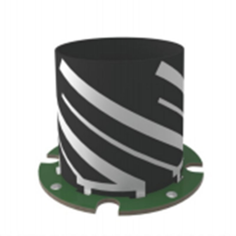
The most common type of radiating element used in high-gain GNSS antennas is the patch antenna, specifically a stacked patch or multilayer patch design. A basic patch antenna consists of a flat metallic element (the patch) placed over a larger ground plane. For GNSS, which uses circularly polarized (CP) signals, the patch is typically fed at two points with a 90-degree phase shift to excite two orthogonal modes, creating the desired CP radiation.
To achieve high gain, a single patch is insufficient. Designers use a stacked configuration where a second, parasitically coupled patch is placed above the primary driven patch. This stacking increases the bandwidth and allows for precise control over the radiation pattern. By carefully optimizing the dimensions, spacing, and alignment of these patches, engineers can "squeeze" the radiation pattern, making it narrower in the elevation plane. This results in higher directivity (and thus gain) towards the boresight (straight up) and steeper attenuation towards the horizon, which is ideal for rejecting multipath.
2. Ground Plane
The ground plane is a critical component that serves multiple purposes: it acts as an electrical mirror for the radiating patch, defines the antenna's pattern (especially its rear and side lobes), and provides shielding from below. For a patch antenna to function correctly, it requires a sufficiently large ground plane. The size of this ground plane directly influences the antenna's gain and pattern. For UAV applications, where size and weight are paramount, the ground plane is often minimized to the smallest effective size, a decision that involves careful simulation and trade-offs to avoid degrading performance.
3. Dielectric Substrates
The space between the patches and between the bottom patch and the ground plane is filled with dielectric substrates. These are specialized materials (e.g., Rogers RO4003, Taconic TLY) with carefully controlled permittivity (εr) and loss tangent (tan δ). A low loss tangent is essential to minimize signal absorption within the material itself, ensuring that the maximum amount of energy is radiated or received. The permittivity affects the electrical size of the patch; a higher permittivity allows for a physically smaller antenna at the cost of potentially reduced bandwidth.
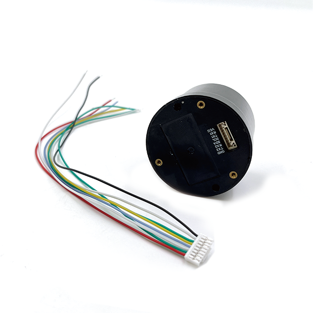
4. Low-Noise Amplifier (LNA)
The received GNSS signals are incredibly weak, often drowned out by the thermal noise floor of the system. Therefore, a high-quality, low-noise amplifier is integrated directly into the antenna housing or located immediately beneath it. The LNA's primary job is to amplify the faint satellite signals before they travel through the lossy coaxial cable to the GNSS receiver. Its key specifications are:
Gain: Typically 25-40 dB, to overcome cable losses.
Noise Figure (NF): Extremely low, often below 1.5 dB, meaning it adds very little noise of its own.
Linearity: A high 1-dB compression point (P1dB) and third-order intercept point (IIP3) to prevent desensitization from strong out-of-band signals (e.g., from cellular or radar).
5. Bandwidth and Multi-Band Operation
Modern high-precision GNSS receivers use signals from multiple constellations (GPS (USA), GLONASS (Russia), Galileo (EU), BeiDou (China)) and on multiple frequencies (e.g., L1, L2, L5). A contemporary high-gain antenna must therefore be multi-band. Designing a single antenna element to operate efficiently across L1 (1575.42 MHz), L2 (1227.60 MHz), and L5 (1176.45 MHz) is a significant challenge. This is achieved through sophisticated stacked-patch designs where different patch layers and feeding techniques are tuned to resonate at these different frequencies simultaneously.
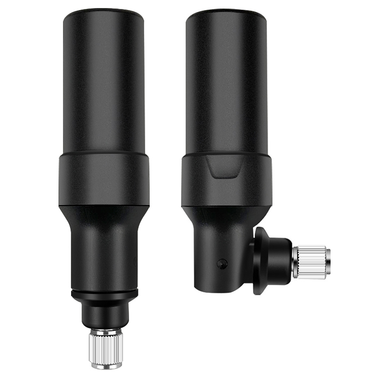
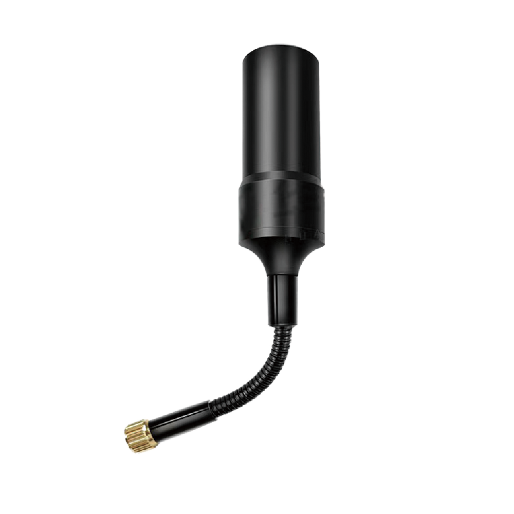
6. Radome and Housing
The entire antenna assembly is protected by a radome—a cover made of material that is transparent to RF signals. For UAVs, this radome must be lightweight (often plastic), aerodynamically shaped to reduce drag, and resistant to UV degradation, moisture, and extreme temperatures. The shape and material of the radome are part of the electromagnetic design, as they can slightly detune the antenna if not properly accounted for.
7. Phase Center and Stability
For high-precision applications like RTK, the most critical design consideration is Phase Center Stability. The phase center is the apparent point from which the radiation emanates. An ideal antenna would have a phase center that is fixed and identical for all frequencies and all angles of arrival. In reality, it moves slightly. A high-quality geodetic antenna is meticulously designed to have a very stable phase center, and its variations are precisely calibrated and documented. The user can then apply these "phase center variation" (PCV) corrections in their processing software to achieve millimeter-level accuracy. This is what separates a truly survey-grade UAV antenna from a simpler navigation-grade one.
In summary, the construction of a high-gain GNSS UAV antenna is a feat of miniaturization and precision engineering. It integrates specialized materials, sophisticated electromagnetic design, and advanced electronics into a robust and lightweight package that can perform reliably in the demanding aerial environment, forming the foundation for all subsequent positioning accuracy.
Understanding how a high-gain GNSS antenna works requires delving into the principles of electromagnetic wave reception, polarization, and pattern shaping. Its operation is not one of active generation but of selective and efficient reception, acting as a transducer that converts electromagnetic energy from satellites into electrical signals for the receiver.
The Fundamental Task: Capturing Circular Polarization
GNSS satellites transmit right-hand circularly polarized (RHCP) signals. This means the electric field of the radio wave rotates clockwise as it propagates through space. This choice is deliberate: RHCP signals are less affected by Faraday rotation (a phenomenon caused by the ionosphere) and reflections tend to reverse the polarization to left-hand circular polarization (LHCP). A high-gain antenna is specifically designed to be sensitive primarily to RHCP signals. This intrinsic property provides the first level of filtering against multipath, as a signal that has bounced off the ground once will likely arrive as LHCP and be partially rejected by the antenna.
Directivity and Gain: The "Telephoto Lens" Effect
The core working principle of a high-gain antenna is directivity. Imagine two lenses for a camera: a fisheye lens and a telephoto lens. The fisheye (omni antenna) sees everything in a very wide field of view but with little detail from any single point. The telephoto lens (high-gain antenna) has a narrower field of view but captures much more detail from the specific area it's pointed at.
Electromagnetically, this is achieved by shaping the antenna's radiation pattern. The radiation pattern is a 3D plot that shows the relative strength of the signal the antenna receives from different directions. A low-gain antenna has a wide, hemispherical pattern. A high-gain antenna's pattern is more "directed" or "pencil-shaped." It has a high peak in the main lobe (pointing towards the zenith) and much lower gains in the side and back lobes.
This focused pattern means the antenna gathers more energy from the satellites near the zenith, which typically provide the best geometry and strongest signals, while being less sensitive to satellites near the horizon, which are more susceptible to atmospheric delays and multipath. The measure of this focusing ability is the gain, expressed in dBi. The higher the dBi, the narrower and more focused the main lobe.
The Signal Chain: From Space to Receiver
Reception: RHCP signals from overhead satellites arrive at the antenna's radiating patch element.
Conversion: The electromagnetic wave induces a tiny, oscillating electrical current in the patch. Due to the dual-feed design, this current correctly represents the RHCP wave.
Pre-amplification: These incredibly weak currents (measured in microvolts or less) are immediately fed into the integrated Low-Noise Amplifier (LNA). The LNA's crucial role is to boost the signal amplitude by 20-40 times (25-40 dB) while adding the absolute minimum amount of electronic noise. This step is vital because the subsequent coaxial cable connecting the antenna to the receiver introduces signal loss (attenuation). Without the LNA at the source, the signal would be irrecoverably buried in noise by the time it reached the receiver.
Filtering: The amplified signal often passes through a bandpass filter, either within the LNA module or as a separate component. This filter allows frequencies in the GNSS bands (L1, L2, L5) to pass through while attenuating strong out-of-band signals from other services like cellular, WiFi, or VHF that could overload the sensitive GNSS receiver.
Transmission: The now-amplified and filtered signal travels down the coaxial cable to the GNSS receiver module within the UAV's flight controller.
Processing: The receiver performs the complex tasks of acquisition, tracking, and demodulation of the signals from multiple satellites to compute the precise position, velocity, and time (PVT) solution.
Maintaining Performance in a Dynamic Environment
A unique challenge for UAV antennas is that the platform is never static. It rolls, pitches, and yaws. A highly directional antenna pointed straight up would perform poorly if the UAV banked 45 degrees, as its main lobe would now be pointing away from the satellite constellation.
To mitigate this, high-gain UAV antennas are designed with a carefully considered half-power beamwidth. This is the angular width of the main lobe where the power is at least half (-3 dB) of its maximum value. A well-designed antenna will have a beamwidth wide enough (e.g., 100-140 degrees) to maintain coverage of the entire upper hemisphere even under typical UAV attitude changes of 20-30 degrees. For applications involving aggressive maneuvering, the antenna's placement on the airframe (e.g., on top of the fuselage) and its wide beamwidth are critical to preventing signal dropouts. For ultimate reliability, some systems may employ two antennas in a diversity configuration, but this is rare due to weight and cost constraints.
In essence, the working principle is one of optimized selectivity and sensitivity. It selectively favors wanted signals (RHCP, from above) over unwanted ones (LHCP multipath, low-elevation noise, and out-of-band interference) and sensitively captures and amplifies the faint satellite signals to provide the cleanest possible data stream to the receiver, enabling it to perform at its theoretical best.
The integration of a high-gain GNSS antenna is a decisive step up from standard solutions, offering compelling advantages but also introducing specific challenges that system designers must address.
Advantages:
Superior Accuracy and Precision: This is the paramount advantage. By providing a stronger, cleaner signal with significantly reduced multipath contamination, the high-gain antenna drastically improves the Signal-to-Noise Ratio (SNR) and carrier-phase measurement quality. This is the foundational requirement for achieving centimeter-level accuracy with RTK or PPP technologies. For applications like aerial LiDAR mapping, photogrammetry, and topographic surveying, this precision is non-negotiable.
Enhanced Reliability and Lock Stability: UAVs operating in challenging environments—such as urban canyons, under forest canopies, or near large metal structures—are prone to GNSS signal degradation and loss. The high-gain antenna's ability to pull in weaker signals and reject reflections makes the satellite lock far more robust. This reduces cycle slips and outright outages, which is critical for autonomous mission execution, automated landing sequences, and overall flight safety.
Increased Operational Range and Flexibility: The improved sensitivity allows the UAV to operate effectively at greater distances from the pilot or base station, and in areas where GNSS coverage would otherwise be marginal. This expands the potential use cases for long-range inspection missions (e.g., power lines, pipelines) and operations in complex environments.
Improved Resistance to Interference: The antenna's radiation pattern provides a first line of defense against both intentional (jamming) and unintentional interference. By being less sensitive to signals arriving from low angles (typically where terrestrial干扰源 are located), it offers a degree of inherent spatial filtering. Furthermore, high-quality integrated filters protect the LNA and receiver from being desensitized by strong non-GNSS signals.
Support for Advanced GNSS Techniques: Modern high-precision positioning relies on using multiple satellite constellations (GPS, GLONASS, Galileo, BeiDou) and multiple frequencies (L1, L2, L5). The multi-band capability of advanced high-gain antennas is essential for leveraging these signals. Using two frequencies (e.g., L1 and L2) allows the receiver to calculate and correct for ionospheric delay, a major source of error, which is impossible with a single-frequency antenna.
Challenges and Considerations:
Size, Weight, and Power (SWaP) Constraints: This is the primary challenge for UAV integration. A high-performance antenna with a large ground plane and stacked patches is inherently larger and heavier than a simple ceramic patch. Every gram and every cubic centimeter counts on a UAV, as it directly impacts flight time, payload capacity, and agility. Integrating a powerful LNA also requires a dedicated power supply from the drone's system.
Aerodynamic Integration: An antenna cannot simply be bolted onto the airframe as an afterthought. Its placement and radome design must minimize drag and avoid disrupting the aerodynamic flow, which could affect flight stability and battery consumption. This often requires custom aerodynamic housings and careful placement studies.
Cost: High-quality materials (low-loss substrates), precision manufacturing, rigorous testing, and phase center calibration make high-gain GNSS antennas significantly more expensive than their consumer-grade counterparts. This can be a barrier to adoption for cost-sensitive applications.
Pattern Sensitivity to Mounting: The antenna's radiation pattern is designed assuming an infinite or large enough ground plane. When mounted on a UAV, the actual airframe becomes part of the antenna system. The carbon fiber body, battery, and other electronic components can detune the antenna, distort its pattern, and shift its phase center. This requires extensive electromagnetic simulation and real-world testing to characterize and mitigate, often leading to custom integration solutions for specific UAV models.
Limited Zenith Coverage During Maneuvers: As discussed, the narrower beamwidth that provides the gain is a double-edged sword. During aggressive banking or pitching, the main lobe may tilt away from the satellite constellation, potentially causing a temporary reduction in the number of satellites tracked or a decrease in SNR. Designers must carefully balance the peak gain with the beamwidth requirements for the intended flight dynamics of the UAV.
Calibration Requirement: For the highest levels of accuracy (geodetic or survey-grade), the antenna's phase center variations must be precisely known. Each antenna model requires individual calibration in an anechoic chamber to generate a PCV map. Users must ensure their processing software supports applying these specific corrections, adding a layer of complexity to the workflow.
In conclusion, while high-gain antennas bring transformative advantages in accuracy and reliability, they demand a systems-level approach to integration. The benefits are immense for professional applications, but they come with tangible costs and engineering challenges that must be thoughtfully managed to realize their full potential.
The unique capabilities of high-gain GNSS antennas have unlocked a vast array of sophisticated UAV applications that were previously impossible or impractical. Furthermore, ongoing advancements promise to further expand these capabilities and open new frontiers.
Current Applications:
Aerial Surveying and Mapping: This is the most demanding application. High-precision RTK/PPK-enabled drones equipped with high-gain antennas are used for creating highly accurate digital elevation models (DEMs), contour maps, and 3D models for construction, mining, archaeology, and civil engineering. The antenna is critical for ensuring that each photograph or LiDAR point is tagged with a centimeter-accurate position.
Precision Agriculture: Drones use multispectral and hyperspectral cameras to assess crop health. To create accurate Normalized Difference Vegetation Index (NDVI) maps and enable variable-rate application of water or fertilizers, the imagery must be precisely geotagged. This requires the stable positioning provided by a high-gain antenna.
Infrastructure Inspection: inspecting power lines, wind turbine blades, cell towers, and bridges often requires flying close to large metal structures that cause severe multipath and signal blockage. A high-gain antenna's resilience is crucial for maintaining a safe and stable position hold, allowing the pilot or autonomous system to focus on capturing inspection data.
LiDAR and Photogrammetry: These technologies are the gold standard for 3D data collection. The point cloud generated by LiDAR or from photogrammetric processing is only as accurate as the platform's trajectory, which is calculated using GNSS/IMU integration. The clean, continuous carrier-phase data from a high-gain antenna is essential for generating a precise trajectory, ensuring the final point cloud is metrically accurate.
Autonomous Logistics and Delivery: For drones to autonomously navigate to a specific landing pad on a hospital roof or in a backyard, they require extremely precise positioning, especially during the final approach and landing phase. A high-gain antenna ensures the drone knows its location with the required certainty to operate safely in potentially congested environments.
Scientific Research and Environmental Monitoring: Applications like glacier monitoring, wildlife tracking, and atmospheric sampling require drones to fly pre-programmed paths repeatedly with high positional repeatability. This is only possible with a high-integrity GNSS solution.
Future Trends:
Tighter GNSS/IMU Sensor Fusion: The future lies in deeply coupled INS (Inertial Navigation System) architectures. Here, the raw data from the GNSS receiver (pseudorange, carrier-phase) and the inertial measurement unit (IMU) are fused at a fundamental level. The role of the high-gain antenna will be to provide the longest possible periods of high-quality GNSS data to continually calibrate and bound the drift of the ultra-accurate, miniaturized IMUs (e.g., MEMS-based tactical grade) that are becoming more affordable.
Anti-Jamming and Anti-Spoofing (AJS) Integration: As airspace becomes more crowded and the threat of intentional interference grows, resilience is paramount. Future high-gain antennas will increasingly be integrated with controlled reception pattern antennas (CRPAs) or will be part of array systems. These systems can electronically form nulls in their radiation pattern in the direction of jammers while maintaining gain towards satellites, providing a powerful hardware-level defense against interference and spoofing attacks.
Multi-Frequency, Multi-Constellation as Standard: Support for all signals from all constellations (GPS L1C/A, L2C, L5; Galileo E1, E5a, E5b, E6; BeiDou B1, B2, B3; etc.) will become the baseline. This "every signal available" approach will provide unparalleled robustness, faster integer ambiguity resolution for RTK, and higher accuracy through advanced atmospheric modeling.
Further Miniaturization and Integration: Advances in materials science (e.g., new dielectric substrates) and manufacturing techniques (e.g., 3D printing of antenna elements) will continue to drive down the size, weight, and profile of high-performance antennas. We will see them more seamlessly integrated into the airframe itself, perhaps as conformal patches that are flush with the fuselage skin, eliminating drag entirely.
AI-Driven Adaptive Antennas: Research is ongoing into "cognitive" antennas that can use AI to dynamically adapt their pattern in real-time based on the RF environment. For example, the antenna could momentarily widen its beamwidth during a sharp turn or create a deeper null towards a newly detected interference source, all while optimizing for the best possible satellite tracking.
Paving the Way for Urban Air Mobility (UAM): The stringent safety and reliability requirements of passenger-carrying air taxis will demand navigation systems with immense integrity. High-gain, anti-jam, multi-antenna GNSS systems will be a foundational technology for UAM, providing the necessary continuous and trustworthy PNT data for navigation in dense urban environments.
The evolution of the high-gain GNSS antenna is thus moving from being a standalone component to becoming an intelligent, integrated node within a robust and resilient PNT system. It will be a key enabler for the next generation of autonomous systems that will operate in increasingly complex and contested environments.
Conclusion
The high-gain GNSS antenna is a quintessential example of how a focused improvement in a fundamental component can catalyze a revolution in system-level capability. For unmanned aerial vehicles, it has transitioned from a peripheral accessory to a mission-critical sensor that sits at the very beginning of the data chain. Its role is passive yet profound: to act as a sensitive and selective collector of the faint whispers of navigation satellites, filtering out the noisy clamor of the RF environment.
As we have explored, the design and construction of these antennas represent a sophisticated fusion of electromagnetic theory, advanced materials science, and precision engineering. The pursuit of higher gain, stable phase center, multi-band operation, and minimal SWaP footprint involves constant trade-offs and innovations. The working principle, centered on directivity and circular polarization, provides the tangible advantages of unparalleled accuracy, robust reliability, and resistance to interference that define modern professional drone operations.
These advantages are not merely academic; they directly enable transformative applications across industries—from creating the digital twins of our world in surveying to optimizing global food production in agriculture, and from maintaining critical infrastructure to envisioning a future of autonomous urban air mobility. The antenna is the unsung hero that makes centimeter-level precision in a dynamic aerial platform not just possible, but routine.
However, this capability does not come without its challenges. The constraints of size, weight, aerodynamics, and cost demand a systems-level approach to integration. The future trends point towards even greater integration, intelligence, and resilience. The antenna will become less of a distinct component and more of an intelligent subsystem, working in deep synergy with IMUs and advanced algorithms to provide assured Positioning, Navigation, and Timing (PNT) even in adverse or contested spectral environments.
In conclusion, as UAVs continue to evolve towards greater autonomy and more complex missions, the demand for precise and reliable PNT will only intensify. The high-gain GNSS antenna, therefore, is not a static technology but a rapidly advancing field that will continue to be a cornerstone of autonomous flight. Its ongoing development will be instrumental in unlocking the full potential of drones, ensuring that they can operate safely, efficiently, and accurately in the skies of today and tomorrow.

 86 0755 2819 9597
Lucy Yang | lucy.y@toxutech.com
Nicole Li | nicole@toxutech.com
Dotty Zhao | sales04@toxutech.com
Global Business Director / Sales Team / Global Operations


 En
En Cn
Cn Korean
 Home >


