

-
Products -PCBA Manufacturing RF Connectors RF Cable Assemblys Embedded Antennas External Antennas Positioning Chips and Modules
RF Connectors

RF Cable Assemblys
Embedded Antennas
External Antennas
Positioning Chips and Modules


 Language


Language


The quest for precision in determining our position on Earth has been a driving force behind human exploration, trade, and scientific discovery for millennia. From celestial navigation to the first terrestrial triangulation surveys, each leap in accuracy has unlocked new possibilities. In the modern era, this quest is dominated by the Global Navigation Satellite System (GNSS), a constellation of satellites broadcasting signals that allow anyone with a receiver to calculate their global position. However, there is a vast chasm between the few-meter accuracy of a standard smartphone GNSS receiver and the centimeter—or even millimeter—level accuracy required for scientific research, critical infrastructure development, and precise geospatial mapping. This chasm is bridged not by the receiver alone, but by a sophisticated and often overlooked component: the high-accuracy GNSS survey antenna.
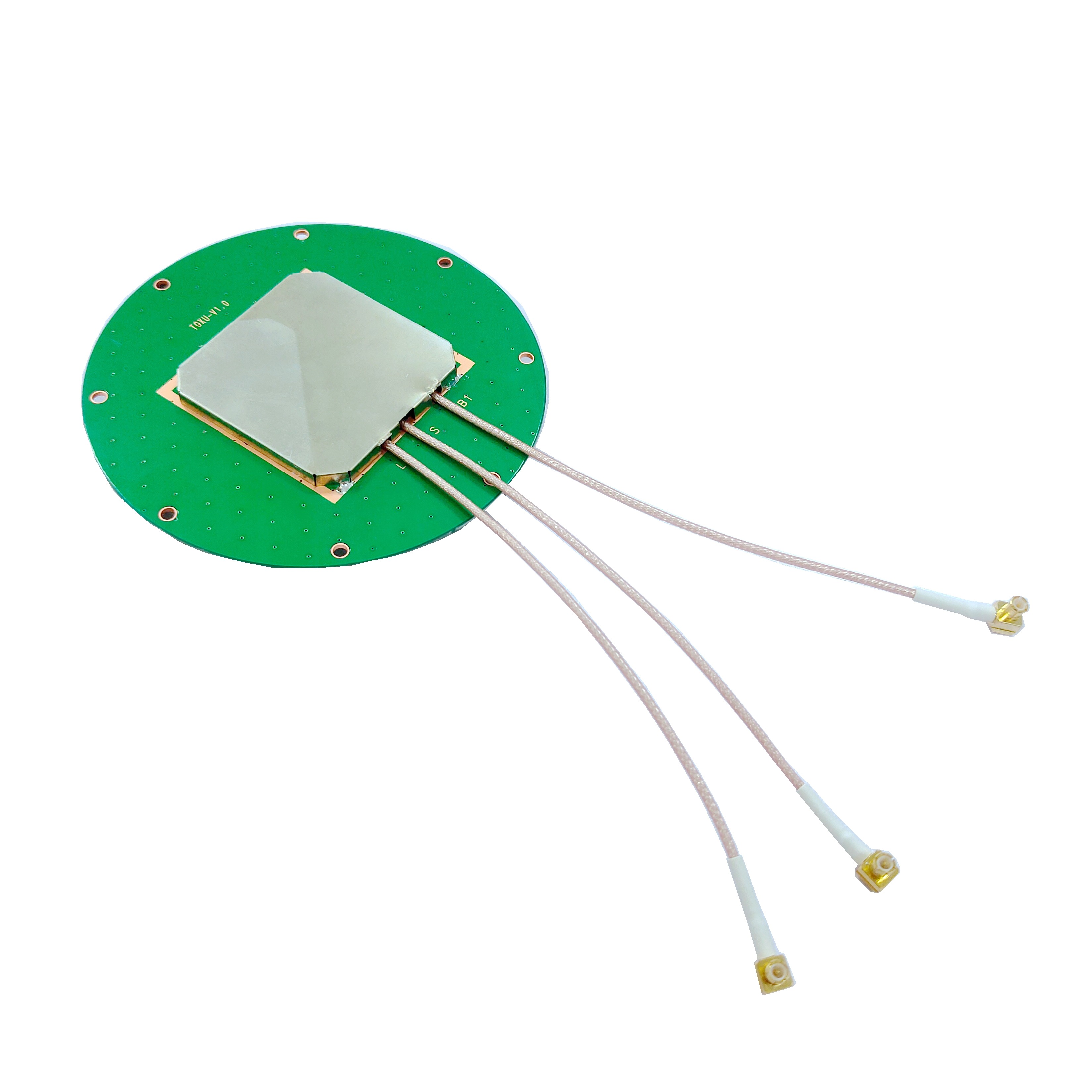
A high-accuracy GNSS survey antenna is the critical first element in the precision positioning chain. It is the specialized transducer responsible for capturing the incredibly weak, right-hand circularly polarized (RHCP) electromagnetic signals transmitted from GNSS satellites orbiting over 20,000 kilometers above the Earth. Unlike consumer-grade antennas, its purpose is not merely to acquire a signal for basic navigation. Instead, its design is meticulously optimized for one paramount objective: to preserve the absolute integrity of the incoming satellite signal's carrier phase and code properties, enabling the most precise measurements possible for professional applications.
The fundamental differentiator of a survey-grade antenna is its role in achieving carrier-phase ambiguity resolution, the cornerstone of high-precision GNSS techniques like Real-Time Kinematic (RTK) and Post-Processed Kinematic (PPK) positioning. These methods rely on measuring the phase of the carrier wave itself, which has a wavelength of just 19 centimeters for the GPS L1 frequency. Measuring the phase to within a small fraction of this wavelength is what enables centimeter-level accuracy. Any corruption of this phase measurement at the antenna—by multipath interference, electronic noise, or instability in the antenna's own characteristics—dooms the entire process. The antenna, therefore, is not just a passive collector; it is the guardian of signal fidelity.
The importance of the antenna becomes starkly clear when considering the signal's journey. A typical GNSS signal arriving at the Earth's surface has a power level on the order of -125 to -130 dBm, meaning it is profoundly weak, buried well below the thermal noise floor of the receiving system. It has traversed the ionosphere and troposphere, being refracted and delayed along the way. Finally, it is vulnerable to multipath—the phenomenon where a signal arrives at the antenna not directly, but after reflecting off the ground, buildings, vehicles, or other obstacles. These reflected signals travel a longer path and are delayed, and their polarization can be altered (often to Left-Hand Circular Polarization, LHCP), introducing errors into the precise timing measurements.
A survey antenna is engineered to combat these challenges through a combination of features:
Controlled Radiation Pattern: It is designed to be highly sensitive to signals arriving from above (high elevations) and significantly less sensitive to signals arriving from near the horizon. Since direct satellite signals come from above and multipath typically arrives from lower angles, this pattern provides inherent multipath mitigation.
Stable Phase Center: This is perhaps the most critical characteristic. The electrical phase center is the point within the antenna from which the radiation appears to emanate. For precise carrier-phase measurements, this point must be stable and consistent for signals arriving from any direction and across all frequencies. Any movement of this point with signal angle or frequency introduces a measurable error that must be modeled and corrected. High-end geodetic antennas have extremely stable phase centers, which are meticulously calibrated.
Multi-Frequency Operation: Modern high-accuracy work requires tracking signals on multiple frequencies (e.g., GPS L1, L2, L5; Galileo E1, E5a, E5b, E6; GLONASS G1, G2, G3; BeiDou B1, B2, B3). Using multiple frequencies allows advanced receivers to model and correct for ionospheric delay, a major source of error. The antenna must perform consistently across all these bands.
Integrated Low-Noise Amplifier (LNA): To overcome the signal weakness and cable losses, a high-quality, low-noise amplifier is integrated directly into the antenna housing. This LNA must provide high gain (e.g., 30-40 dB) while adding the absolute minimum amount of electronic noise of its own, quantified by a very low Noise Figure (e.g., < 2 dB).
The applications that depend on this level of precision are diverse and critical:
Geodesy and Crustal Motion Monitoring: Measuring tectonic plate movement (mm/year) requires the utmost stability and accuracy.
Precision Agriculture: Guiding tractors and variable rate application of inputs based on sub-field variability.
Construction Machine Control: Guiding bulldozers and graders to design specifications without stakes.
Surveying and Mapping: Establishing precise control points and conducting topographic surveys.
Scientific Research: Monitoring glacier melt, sea-level rise, and atmospheric water vapor content.
Autonomous Vehicles: Providing a precise ground-truth position for testing and operation.
In essence, the high-accuracy GNSS survey antenna is the gatekeeper of precision. It is a masterpiece of electromagnetic engineering that transforms a ubiquitous utility—satellite navigation—into a powerful scientific and industrial tool. Its design represents a constant battle against physics to extract perfect information from an imperfect and noisy signal, forming the unshakeable foundation upon which all high-precision GNSS is built.
The design of a high-accuracy GNSS antenna is a complex, multi-disciplinary endeavor that balances electromagnetic theory, material science, mechanical engineering, and electrical engineering. Every aspect of its construction is meticulously optimized to achieve the overarching goals of phase center stability, multipath rejection, wide bandwidth, and operational robustness. It is a device where seemingly minor details, like the choice of a dielectric material or the placement of a grounding screw, can have a profound impact on performance.
Core Radiating Element: The Stacked Patch Antenna
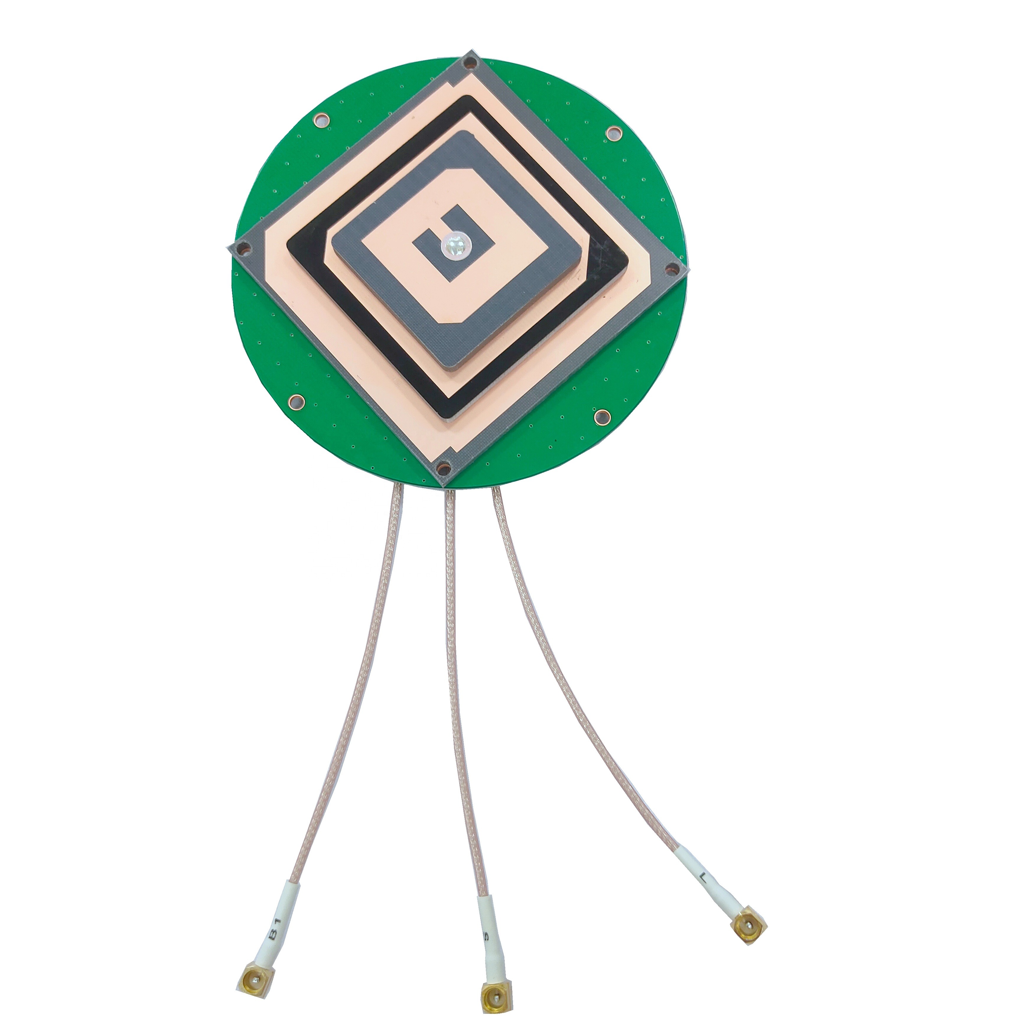
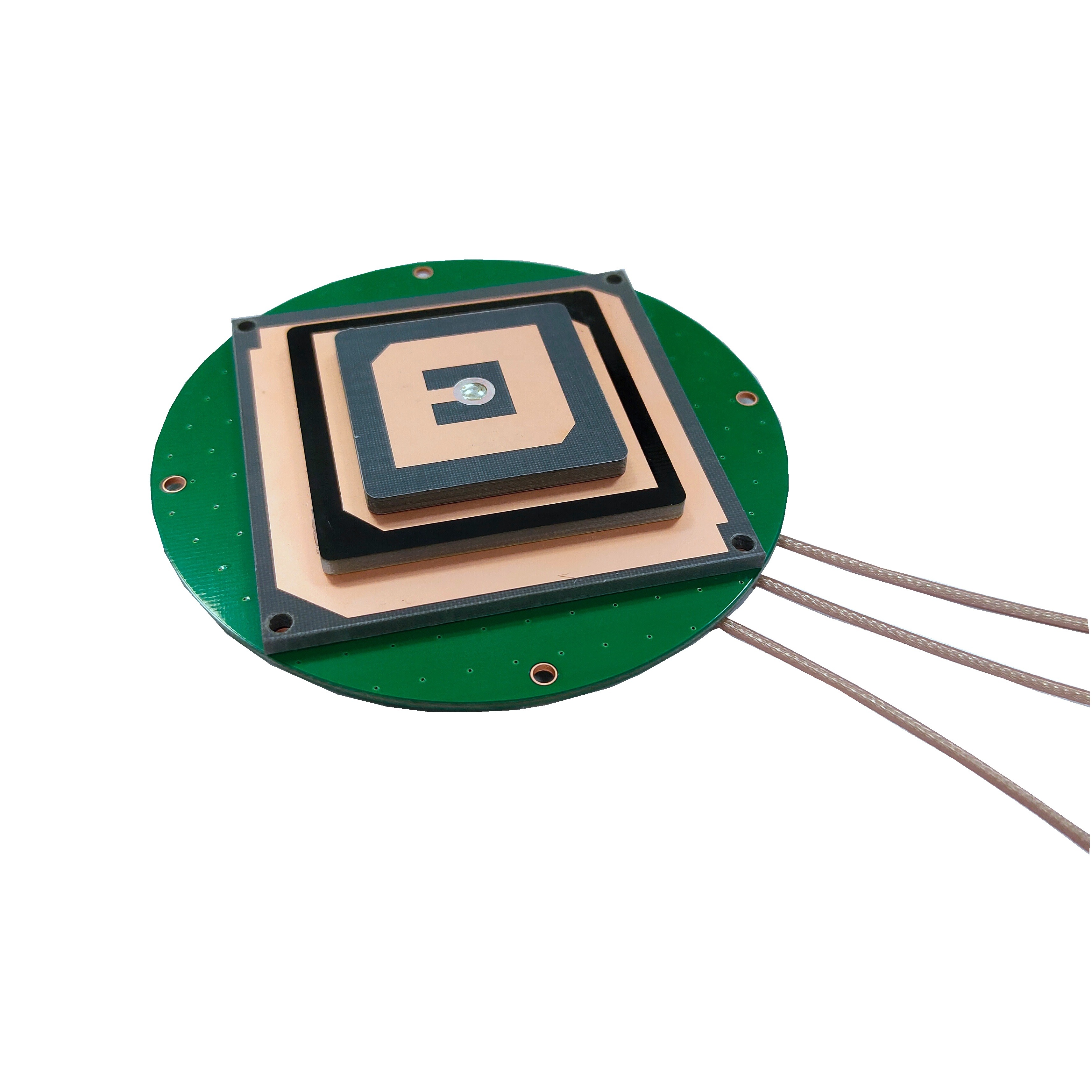
The predominant design for high-end geodetic antennas is the stacked or multi-ring patch antenna. This is a significant evolution from the simple microstrip patch antenna found in consumer devices.
Single Patch Limitations: A basic patch antenna has limitations in bandwidth and its ability to control the radiation pattern with sufficient precision. Its phase center can also vary significantly with frequency and angle of arrival.
Stacked Design: The stacked patch design uses multiple concentric radiating elements (patches) separated by dielectric layers. Typically, there is a lower, driven patch that is directly connected to the feed network, and one or more upper, parasitic patches that are electromagnetically coupled to the driven patch. This structure allows engineers to independently control different aspects of performance:
The lower patch and its feed determine the primary resonance and polarization.
The upper parasitic patches act as resonators themselves, but their primary role is to broaden the operational bandwidth significantly. They allow the antenna to cover multiple GNSS bands (e.g., 1150-1300 MHz for L2/L5 and 1550-1610 MHz for L1/E1) with high efficiency.
The interaction between the patches provides additional degrees of freedom to shape the radiation pattern and stabilize the phase center across the entire bandwidth.
The Critical Role of the Ground Plane
The ground plane is not merely a mechanical base; it is an integral part of the antenna's electromagnetic performance. It serves as a reflector, creating the directional pattern that is essential for gain and multipath rejection.
Size and Shape: The size of the ground plane directly influences the antenna's gain and its radiation pattern, particularly the sharpness of the roll-off at low elevation angles. A larger ground plane generally provides better suppression of signals from below the horizon (diffracted and reflected signals) and improves the symmetry of the phase center. Most geodetic antennas use a ground plane with a diameter between 10 cm and 15 cm, often with a choked or serrated edge.
Choked or Serrated Ground Plane (Choke Ring): The most effective design for multipath suppression is the choke ring ground plane. This features concentric, circular troughs (rings) of a specific depth (approximately a quarter-wavelength at the target frequency) machined into the ground plane. These rings present a very high impedance (a "choke") to surface currents induced by low-angle signals, particularly those arriving from below the horizon. This effectively prevents these unwanted signals from being radiated (or received) by the antenna element. While extremely effective, choke rings are bulky and heavy. Modern designs often use smaller, optimized ground planes with radial or other patterns to achieve a similar, though less absolute, effect in a more compact form factor.
Dielectric Materials and Substrates
The space between the patches and between the bottom patch and the ground plane is filled with dielectric substrates. The choice of material is critical.
Key Properties: The two most important properties are Dielectric Constant (εr) and Loss Tangent (tan δ).
A higher dielectric constant allows for a smaller physical antenna size for a given electrical wavelength, but it often at the expense of bandwidth.
A low loss tangent is absolutely non-negotiable. It ensures that the dielectric material absorbs a minimal amount of the RF energy, maximizing radiation efficiency. Materials like Rogers RO4003C or Taconic TLY are common choices, with loss tangents on the order of 0.002 to 0.004.
Humidity Resistance: The materials must be hydrophobic and stable under varying humidity conditions, as water ingress would drastically alter the dielectric constant and ruin performance.
Feed Network and Polarization
Creating pure Right-Hand Circular Polarization (RHCP) is essential.
Dual-Feed Technique: The most common method is to feed the patch at two orthogonal points with a 90-degree phase shift between them. This excites two degenerate orthogonal modes that, combined, create the circular polarization. This requires a precise and stable internal feed network, often using printed circuit board (PCB) traces or stripline techniques to create the necessary phase shift.
Axial Ratio: The quality of the circular polarization is measured by the axial ratio. A perfect circularly polarized wave has an axial ratio of 0 dB. A practical antenna strives for an axial ratio as close to 0 dB as possible across its entire operating band and for all elevation angles above the cutoff. A poor axial ratio means the antenna is somewhat receptive to LHCP signals (like multipath), introducing measurement error.
Low-Noise Amplifier (LNA) and Filtering
The integrated LNA is a masterpiece of low-noise RF design.
Noise Figure (NF): The primary specification is an extremely low Noise Figure, typically below 2 dB and often below 1.5 dB for the best models. This means the LNA adds almost negligible noise to the already-weak signal. This is achieved using specialized Gallium Arsenide (GaAs) or Gallium Nitride (GaN) FET transistors.
Gain: The LNA provides high gain, usually between 25 dB and 40 dB, to overcome the losses in the coaxial cable that connects the antenna to the receiver. This ensures that the signal presented to the receiver is strong enough to be digitized and processed effectively.
Linearity and Filtering: The LNA must have high linearity (high IP3) to avoid being desensitized or generating intermodulation products from strong out-of-band signals like cellular, VHF, or radar. Bandpass filters are integrated before and/or after the amplification stages to reject these interfering signals while passing the GNSS bands unimpeded.
Radome and Mechanical Housing
The entire assembly is protected by a radome.
RF Transparency: The radome material must be virtually invisible to RF signals. Materials like polycarbonate or ABS plastic are common, but their thickness and dielectric properties are carefully chosen to minimize any reflection or phase distortion.
Environmental Protection: The housing must be waterproof (IP67 rating or higher), UV-resistant to prevent degradation from sun exposure, and robust enough to withstand physical impact and temperature cycling. A common feature is a desiccant chamber inside the housing to absorb any residual moisture that might enter through cable connectors over time.
Phase Center Calibration
The final, and arguably most important, step in the life of a geodetic antenna model is not manufacturing, but calibration. The precise 3D location of its average phase center and, more importantly, its variations with elevation and azimuth (Phase Center Variations, or PCVs) must be measured in an anechoic chamber. These PCV values are published in ANTEX (Antenna Exchange) format files. For centimeter- or millimeter-level work, surveyors must apply these corrections in their processing software to correct for the antenna's inherent imperfections. This calibration is what truly separates a geodetic antenna from a high-quality navigation antenna.
In summary, the construction of a high-accuracy GNSS antenna is an exercise in controlling every variable. It is a precision instrument where advanced materials, sophisticated electromagnetic design, and ultra-low-noise electronics converge to create a stable and reliable reference point for measuring the Earth itself.
The operation of a high-accuracy GNSS antenna is a sophisticated process of selective reception, amplification, and preservation of signal integrity. Its working principles are fundamentally different from a simple navigation antenna, as its goal is not just to acquire a signal, but to measure it with extreme precision. The entire process can be broken down into a sequence of critical functions.
1. Selective Reception and the Radiation Pattern
The antenna's radiation pattern is its most important functional characteristic. This 3D plot defines how sensitive the antenna is to signals arriving from different directions.
High Directivity and Gain: The pattern is designed to be highly directional towards the zenith (directly overhead). This focus provides gain, typically between 5 dBi and 15 dBi for signals from above. This is analogous to using a telephoto lens instead of a wide-angle lens; it gathers more energy from the desired direction (where the satellites are) and less from others.
Multipath Rejection via Pattern Shaping: The key to its performance is the steep roll-off in gain for signals arriving at low elevation angles (below 5-10 degrees). Since direct satellite signals rarely appear below 5 degrees (due to atmospheric and other errors), and multipath reflections predominantly come from these low angles and from the ground, this shaped pattern provides powerful, passive multipath suppression. The choke ring ground plane enhances this effect by "choking off" any surface currents that would re-radiate these low-angle signals.
2. Preservation of Signal Polarization: RHCP Fidelity
GNSS satellites transmit Right-Hand Circularly Polarized (RHCP) signals. When this signal reflects off a surface, its polarization often becomes elliptical or reverses to Left-Hand Circular Polarization (LHCP).
Polarization Purity: The antenna's dual-feed network is designed to be maximally sensitive to RHCP and minimally sensitive to LHCP. This is quantified by its axial ratio. A good survey antenna maintains a very low axial ratio (close to 0 dB) for all high-elevation angles. This means it efficiently receives the direct RHCP satellite signal while naturally rejecting a significant portion of the reflected LHCP multipath signal. This is a second, powerful layer of multipath mitigation.
3. The Low-Noise Amplification Chain
The signal path inside the antenna is crucial for maintaining the signal-to-noise ratio (SNR).
Front-End LNA: The faint signals captured by the radiating element (on the order of -125 to -130 dBm) are immediately fed into the integrated Low-Noise Amplifier (LNA). The LNA's primary job is to amplify the voltage of these signals by a factor of 30 to 100 (30-40 dB) before any significant cable loss can occur.
The Noise Figure Imperative: The critical specification is the LNA's Noise Figure (NF). Every electronic component at a temperature above absolute zero generates thermal noise. The LNA is designed to add the absolute minimum amount of this inherent electronic noise to the signal. A low NF (e.g., 1.5 dB) means that the amplified signal is primarily the original satellite signal plus a very small amount of amplifier noise. If the NF were high, the signal would be "buried" in the amplifier's own noise, making precise phase measurements impossible. This is why the LNA is placed at the antenna; placing it after a long, lossy cable would mean amplifying both the weakened signal and the cable's thermal noise, resulting in a catastrophically poor SNR.
Filtering for Purity: After or within the amplification stage, bandpass filters are employed. These allow the desired GNSS frequencies (e.g., 1164-1300 MHz and 1559-1610 MHz) to pass through with minimal attenuation, while aggressively rejecting strong out-of-band signals from other services like cellular (700-900 MHz, 1800-2100 MHz), WiFi (2.4 GHz, 5 GHz), and VHF communications. This prevents these powerful signals from overloading the LNA or the downstream receiver, a phenomenon known as desensitization.
4. Phase Center Stability: The Heart of Precision
This is the most fundamental principle for high-accuracy carrier-phase measurements.
The Concept of the Phase Center: In an ideal antenna, there would be a single, precise point from which the electromagnetic radiation appears to originate. This is the phase center. For carrier-phase measurements, the receiver measures the distance between the satellite's phase center and the antenna's phase center. If the antenna's phase center were a perfect, stable point, this measurement would be perfect.
The Reality of Phase Center Variation (PCV): In a real antenna, the apparent phase center is not a fixed point. It moves slightly depending on the elevation and azimuth of the incoming satellite signal and the frequency being used. This movement is called Phase Center Variation (PCV).
How a Survey Antenna Manages PCV: The design goal of a geodetic antenna is to minimize these variations and, crucially, to make them highly predictable and stable over time. Through the symmetric stacked-patch design and a high-quality ground plane, the PCVs are reduced to a few millimeters. Furthermore, the antenna's PCV pattern is meticulously calibrated in an anechoic chamber. This calibration data (provided in ANTEX files) allows software to correct the raw measurements, effectively subtracting the antenna's own "imperfections" from the data. Without this calibration and a stable antenna design, PCV could introduce errors of several centimeters, completely negating the benefits of high-precision techniques.
5. Multi-Frequency Operation
Modern precision GNSS relies on using multiple frequencies to correct for ionospheric delay.
Ionospheric Delay: The ionosphere, a layer of charged particles in the upper atmosphere, slows down GNSS signals. The amount of delay is frequency-dependent.
Dual-Frequency Correction: By measuring the same signal on two different frequencies (e.g., L1 and L2), the receiver can calculate the exact amount of ionospheric delay and remove it from the measurement. This is the largest source of error eliminated by multi-frequency systems.
Antenna Requirement: The antenna must therefore operate efficiently across all required bands. The stacked-patch design is inherently broadband, allowing it to cover the L2/L5 and L1 bands simultaneously with consistent performance. The phase center for each band must also be stable and its offset from the other bands well-calibrated.
In functional terms, the antenna acts as a precision filter and pre-conditioner. It:
Spatially filters signals via its radiation pattern.
Polarization filters signals via its axial ratio.
Spectrally filters signals via its integrated bandpass filters.
Amplifies the desired signals with minimal added noise.
Provides a stable electrical reference point (phase center) for all measurements.
This multi-layered approach to signal integrity ensures that the data delivered to the GNSS receiver is of the highest possible quality, providing the raw material from which centimeter-level positions are forged.
The deployment of a high-accuracy GNSS survey antenna brings a transformative set of advantages to any precision positioning application. However, these advantages are coupled with significant challenges and considerations that must be thoroughly understood by system integrators and end-users to justify the investment and achieve optimal performance.
Advantages
Unmatched Accuracy and Precision: This is the primary and most significant advantage. By providing exceptional phase center stability and aggressively suppressing multipath, these antennas enable reliable and rapid carrier-phase ambiguity resolution. This is the process that allows RTK and PPK techniques to achieve centimeter-level, and sometimes millimeter-level, positioning accuracy. This precision is simply unattainable with standard antennas, whose unstable phase centers and multipath errors swamp the small carrier-phase measurements.
Superior Multipath Mitigation: Multipath is a dominant source of error in precision GNSS, especially in challenging environments like urban canyons, near buildings, or in areas with reflective surfaces. The combination of a choked ground plane and a carefully shaped radiation pattern provides the most effective passive defense against multipath. This results in more reliable positioning, fewer cycle slips, and higher data integrity, which directly translates to increased productivity for surveyors and fewer re-measurements.
Enhanced Reliability and Data Integrity: The high gain towards the zenith and the excellent signal-to-noise ratio (SNR) provided by the low-noise LNA ensure robust satellite tracking. This is crucial for maintaining lock on satellites, particularly during periods of low satellite visibility or when operating under light foliage. The stability of the system means that positions are not just precise but also trustworthy and repeatable over time, which is essential for monitoring applications like deformation studies.
Support for Advanced GNSS Techniques: These antennas are a prerequisite for leveraging the full capabilities of modern multi-constellation, multi-frequency (MCMF) GNSS receivers. They provide the clean, stable data needed for advanced techniques like:
PPP-RTK: A technique combining the advantages of Precise Point Positioning and RTK, requiring utmost signal quality.
Ionospheric and Tropospheric Modeling: The high-quality multi-frequency data is used by scientists to model atmospheric conditions.
Integer Ambiguity Resolution on-the-fly: The stability allows receivers to resolve the integer ambiguities faster and more reliably, reducing initialization times.
Long-Term Stability and Calibration: A key advantage of professional-grade antennas is their predictability. Their phase center variations are not just small; they are stable over time and temperature, and more importantly, they are precisely calibrated. This allows users to apply antenna-specific corrections (from ANTEX files) in their processing software, removing a systematic error source and ensuring that results are consistent and accurate across different antennas of the same model. This is critical for large-scale projects involving multiple survey teams or permanent reference station networks.
Challenges and Considerations
Cost: This is the most immediate barrier. The complex design, expensive low-loss dielectric materials, precision machining (especially for choke rings), rigorous testing, and calibration process make high-accuracy antennas significantly more expensive than consumer or even general-purpose survey antennas. Prices can range from several hundred to several thousand dollars per unit, representing a major investment.
Size, Weight, and Power (SWaP): Performance comes at a physical cost. A full choke ring antenna is large, heavy, and cumbersome, requiring a sturdy tripod or permanent monumentation. Even modern compact geodetic antennas are larger and heavier than their navigation counterparts. The integrated LNA also requires a power source, typically supplied through the coaxial cable (bias-teeing) from the receiver, which must be accounted for in system design.
Calibration and Model Dependency: The advantage of phase center calibration introduces a operational complexity. Users must ensure that:
They are using the correct antenna model calibration file (ANTEX).
Their processing software is correctly applying these calibrations.
The antenna model on the base/reference station is also calibrated and that its calibration is being used. Mismatched antenna models or incorrect calibration application can introduce errors larger than those the antenna was designed to eliminate.
Precise Mounting and Alignment: For the highest accuracy, particularly in static surveying, the antenna must be precisely leveled and centered over a survey marker. This requires high-quality tribrachs, optical plummets, and careful setup. Any misleveling introduces a horizontal error. Furthermore, the antenna's orientation (azimuth) can sometimes affect results if the phase center variations are not perfectly symmetric, though this is minimal in well-calibrated models.
Environmental Sensitivity: While designed to be robust, extreme environmental factors can affect performance. Although the housing is waterproof, condensation inside the radome can occur under certain conditions, drastically altering the antenna's properties. Extreme temperature swings can cause slight mechanical expansions and contractions, though high-quality designs minimize the associated electrical drift.
The Law of Diminishing Returns: For many applications, the extreme performance of a top-tier geodetic antenna with a choke ring may be overkill. A project requiring 2-3 cm accuracy in open-sky conditions might be perfectly served by a smaller, lighter, and less expensive survey-grade antenna without a full choke ring. Understanding the accuracy requirements of the specific application is crucial to selecting the right antenna and avoiding unnecessary cost and complexity.
In conclusion, the advantages of high-accuracy GNSS antennas are profound, enabling a level of precision that forms the bedrock of modern geodesy and precision surveying. However, reaping these benefits requires a clear understanding of the associated challenges: significant financial investment, careful handling and setup, and a meticulous approach to data processing with correct calibration models. They are instruments for professionals who understand that in the world of precision GNSS, the chain of accuracy is only as strong as its first link—the antenna.
The capabilities of high-accuracy GNSS antennas have catalyzed a revolution across a vast spectrum of industries and scientific disciplines. Their unique ability to provide a stable, precise, and reliable geometric reference point has moved from being a specialized tool for surveyors to a fundamental enabling technology for the 21st century. Simultaneously, the field is not static; ongoing technological advancements are continuously expanding the boundaries of what is possible.
Applications
Geodesy and Earth Sciences: This is the most demanding application, where antennas are pushed to their limits.
Tectonic Plate Monitoring: Networks of permanent GNSS reference stations, equipped with the most stable choke ring antennas, measure crustal motions with millimeter-level accuracy over years and decades, providing critical data for understanding plate tectonics and earthquake hazards.
Volcanic Deformation Monitoring: Antennas installed on volcanoes measure the infinitesimal swelling and deflation of the ground, providing预警 for potential eruptions.
Post-Glacial Rebound: Measuring the slow rise of landmasses after the removal of ice-age glaciers.
Sea Level Rise: Precise positioning of tide gauges relative to a global reference frame.
Precision Agriculture: This is one of the largest commercial markets.
Auto-Guidance: High-accuracy antennas guide tractors and implements with 2-3 cm pass-to-pass accuracy, eliminating overlaps and gaps, saving fuel, seed, and fertilizer, and increasing yield.
Variable Rate Technology (VRT): Precise positioning allows farmers to create detailed yield maps and then apply inputs (water, fertilizer, pesticide) at variable rates across a field based on need, optimizing resources and reducing environmental impact.
Construction and Machine Control:
Grade Control: Antennas mounted on bulldozers, graders, and excavators allow them to precisely shape land to a digital design model without the need for traditional survey stakes. This increases speed, accuracy, and safety on job sites.
Building Information Modeling (BIM): Integrating precise GNSS positions with BIM models allows for accurate machine guidance on complex construction projects and for verifying the as-built position of components.
Surveying, Mapping, and GIS:
Control Networks: Establishing highly accurate primary control points for regional and project surveys.
Topographic and Cadastral Surveying: Rapidly mapping features and boundaries with centimeter accuracy using RTK-rover systems.
Aerial Mapping (PPK): Mounted on drones or manned aircraft, these antennas provide the precise camera position needed for generating highly accurate orthophotos and 3D models without the need for extensive ground control points.
Scientific Research:
Atmospheric Sensing: By measuring the delay of GNSS signals through the atmosphere, scientists can derive the total water vapor content, providing data for weather forecasting and climate studies. This is called GNSS Meteorology or GNSS-IR.
Cryosphere Studies: Monitoring the movement and melt of glaciers and ice sheets.
Autonomous Systems and Emerging Applications:
Autonomous Vehicle Testing: Providing the ground-truth position for testing and validating the navigation systems of self-driving cars and trucks.
Robotics: Enabling outdoor autonomous navigation for robots in agriculture, mining, and security.
Asset Tracking: Monitoring the precise position of high-value assets or critical infrastructure for movement or deformation.
Future Trends
The future of high-accuracy GNSS antennas is focused on achieving higher performance in smaller, smarter, and more integrated packages.
Miniaturization and SWaP Reduction: The drive is towards achieving geodetic-grade performance in smaller, lighter, and lower-power antennas. This is critical for drone applications, autonomous systems, and personal portability. Advances in materials (e.g., new dielectrics), manufacturing techniques (e.g., 3D printing of metalized components), and design simulation are making this possible. We will see the performance of choke rings approximated in packages a fraction of the size.
Tighter Integration with IMUs and Sensors: The future is not standalone antennas, but deeply integrated Inertial Navigation System (INS) modules. The antenna will be co-designed with a high-grade IMU (MEMS or FOG) and a processor into a single, tightly coupled unit. This allows for continuous precise positioning even during short GNSS outages (under bridges, in tunnels, under foliage) by using the IMU to "dead reckon." The antenna provides the continuous calibration for the IMU's drift.
Advanced Multi-Antenna Systems: Systems with multiple antenna elements will become more common for two purposes:
Attitude Determination: Using multiple antennas on a single platform (e.g., on a car, ship, or aircraft) to compute not just position, but also precise heading, pitch, and roll. This is valuable for machine control, aviation, and marine navigation.
Advanced Anti-Jamming and Spoofing: Controlled Reception Pattern Antennas (CRPAs) use multiple elements and electronic processing to actively form nulls in the antenna pattern in the direction of jammers or spoofers while preserving gain towards satellites. As the threat of intentional interference grows, this technology will trickle down from military to high-value civilian applications.
AI and Cognitive Antennas: Research is exploring the use of artificial intelligence to create "cognitive" or "adaptive" antennas. The antenna system could use AI to:
Dynamically adapt its pattern in real-time to nullify a newly detected interference source.
Optimize its parameters for the current environment (e.g., urban canyon vs. open sky).
Identify and flag spoofing attacks based on signal characteristics.
Expanded Frequency Support: As new satellites are launched with new signals (e.g., L1C, L2C, L5, and the upcoming L1C for GPS), and as other systems like Low Earth Orbit (LEO) satellite constellations (e.g., Starlink) are explored for positioning, antennas will need to support an even wider range of frequencies seamlessly. The design challenge will be to maintain phase center stability across an ever-broadening bandwidth.
Pervasive High-Accuracy Positioning: The ultimate trend is the democratization of high accuracy. We are already seeing this with the advent of Consumer-Grade RTK modules in smartphones and drones. While their antennas will never match dedicated geodetic models, the algorithms and infrastructure (correction networks) are improving to extract better performance from them. This will create a massive new market for applications requiring sub-meter to decimeter accuracy, further driving innovation in compact antenna design.
In summary, the application space for high-accuracy antennas is vast and growing, fueled by the demand for automation and data-driven decision-making across all sectors. The future will be characterized by antennas that are not just passive components but intelligent, integrated subsystems that are smaller, more robust, and capable of providing assured PNT (Positioning, Navigation, and Timing) in increasingly challenging and contested environments.
Conclusion
The high-accuracy GNSS survey antenna stands as a testament to the profound impact that a focused advancement in a fundamental technology can have on the world. It is far more than a simple component; it is the cornerstone of the entire high-precision GNSS ecosystem. Its development represents a relentless pursuit of perfection in the face of immense physical challenges: capturing unimaginably weak signals from distant satellites while rejecting a cacophony of noise, interference, and reflections here on Earth.
Through this exploration, we have seen that its value is not defined by a single feature but by a symphony of meticulously engineered characteristics: the controlled radiation pattern that spatially filters multipath; the stable phase center that provides a trustworthy electrical reference point; the ultra-low-noise amplifier that preserves the signal-to-noise ratio; and the rigorous calibration that transforms a physical device into a precision measurement instrument. This combination enables the carrier-phase-based techniques that deliver centimeter-level accuracy, unlocking possibilities that were once the domain of science fiction.
The applications it enables are diverse yet universally critical. From monitoring the slow, powerful drift of tectonic plates to guiding agricultural machinery with sub-inch precision; from shaping the modern built environment to its digital design to providing the foundational data for understanding our changing climate, this technology has become deeply embedded in the infrastructure of modern society. It is a key enabler of efficiency, safety, and scientific discovery.
However, this power comes with commensurate responsibilities and challenges. The cost, size, and complexity of these systems demand expertise. Their performance is contingent upon correct calibration, careful setup, and an understanding of their limitations. The field is not static but is evolving rapidly towards a future of miniaturization, deeper sensor integration, and greater intelligence. The trends point towards antennas that are not merely passive collectors but active, cognitive elements of resilient PNT systems, capable of navigating the increasingly crowded and contested electromagnetic spectrum.
In conclusion, the high-accuracy GNSS survey antenna is a masterpiece of engineering that transforms a global utility into a powerful tool for progress. It is the unsung hero at the beginning of the data chain, the guarantor of signal integrity, and the foundation upon which modern precision is built. As our world becomes more automated and our need for precise spatial information grows, the role of this technology will only become more central, continuing to push the boundaries of what we can measure, build, and understand.

 86 0755 2819 9597
Lucy Yang | lucy.y@toxutech.com
Nicole Li | nicole@toxutech.com
Dotty Zhao | sales04@toxutech.com
Global Business Director / Sales Team / Global Operations


 En
En Cn
Cn Korean
 Home >


