

-
Products -PCBA Manufacturing RF Connectors RF Cable Assemblys Embedded Antennas External Antennas Positioning Chips and Modules
RF Connectors

RF Cable Assemblys
Embedded Antennas
External Antennas
Positioning Chips and Modules


 Language


Language


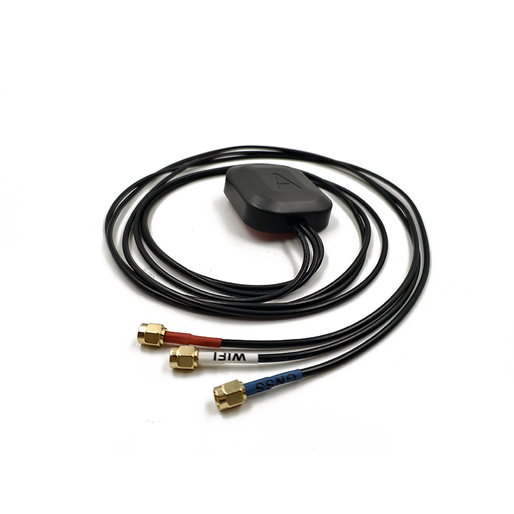
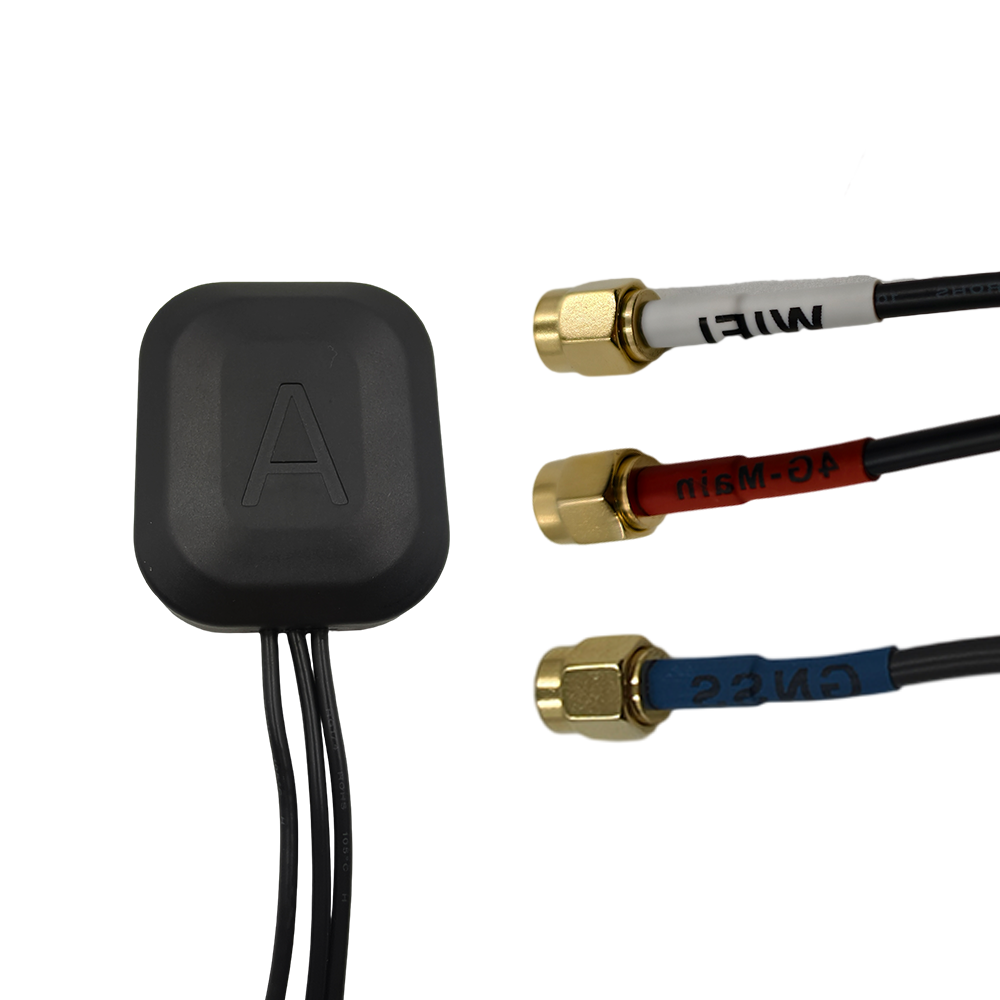
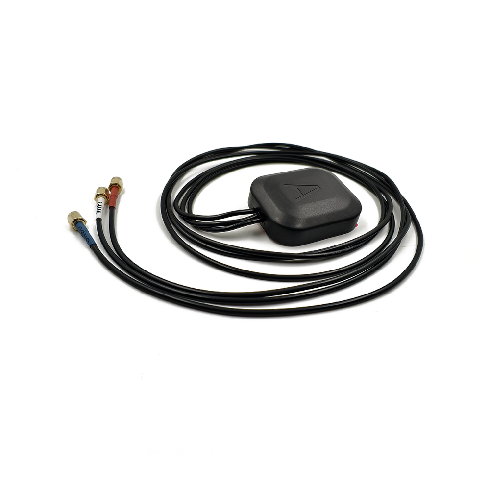
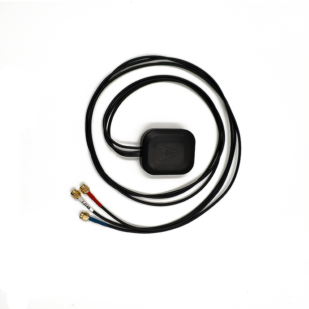

In the realm of high - precision positioning technologies, the High - Precision Multi - Band RTK (Real - Time Kinematic) Ceramic Antenna has emerged as a pivotal innovation, redefining the standards for accuracy, reliability, and adaptability. This antenna type integrates three core attributes—high precision, multi - band compatibility, and a ceramic - based structure—to meet the escalating demands of industries that rely on real - time, centimeter - level positioning data.
First, let’s clarify the key terms that define this antenna. “High precision” is the cornerstone, referring to the antenna’s ability to support RTK technology, which delivers real - time positioning accuracy down to the centimeter or even millimeter level. This is a significant leap beyond traditional single - band GNSS (Global Navigation Satellite System) antennas, which typically offer meter - level accuracy and are insufficient for applications requiring meticulous spatial control. “Multi - band” denotes the antenna’s capacity to receive and process signals across multiple frequency bands from various GNSS constellations, including GPS (e.g., L1, L2, L5 bands), GLONASS (G1, G2), Galileo (E1, E5a, E5b), and BeiDou (B1I, B2I, B3I). By accessing multiple bands, the antenna mitigates signal interference, improves satellite visibility in challenging environments, and enhances positioning stability. “Ceramic” highlights the critical role of ceramic materials in the antenna’s structure—ceramic substrates, in particular, are chosen for their exceptional electrical properties, thermal stability, and mechanical robustness, which are essential for maintaining performance in harsh operating conditions.
The development of High - Precision Multi - Band RTK Ceramic Antennas is driven by a confluence of industry needs and technological advancements. In recent decades, sectors such as precision agriculture, autonomous transportation, construction surveying, and geospatial mapping have experienced a surge in demand for more accurate and reliable positioning solutions. For instance, in precision agriculture, farmers require precise guidance for seeding, fertilizing, and harvesting equipment to optimize crop yields and reduce resource waste—this demands positioning systems that can operate consistently across large fields, even in areas with partial satellite signal blockage. Similarly, autonomous vehicles rely on high - precision positioning to navigate safely through complex urban environments, where tall buildings, tunnels, and other obstacles often disrupt single - band signals.
Technologically, the proliferation of multi - constellation GNSS networks has been a key enabler. With GPS, GLONASS, Galileo, and BeiDou all expanding their satellite fleets and introducing new frequency bands (e.g., GPS L5, a civilian - focused band with enhanced interference resistance), there is a growing need for antennas that can leverage these diverse signals. Ceramic materials, long used in electronics for their low dielectric loss and high thermal conductivity, have become the material of choice for antenna substrates. Unlike traditional plastic or metal substrates, ceramic substrates minimize signal attenuation, ensuring that weak GNSS signals are captured and amplified with minimal distortion—critical for maintaining the high precision required for RTK operations.
Another factor driving the adoption of these antennas is the trend toward miniaturization and integration. Modern devices, from handheld surveying tools to small unmanned aerial vehicles (UAVs), require compact, lightweight components that do not compromise performance. Ceramic antennas, with their dense structure and ability to be fabricated in small form factors, are well - suited to this trend. Their mechanical strength also makes them durable, capable of withstanding vibrations, temperature fluctuations, and moisture—common challenges in outdoor and industrial applications.
To contextualize the significance of High - Precision Multi - Band RTK Ceramic Antennas, it is helpful to compare them to other antenna types. Single - band RTK antennas, for example, are limited to a single frequency band (e.g., GPS L1), making them vulnerable to signal interference from atmospheric conditions (such as ionospheric delays) or man - made sources (such as radio frequency (RF) noise). Multi - band antennas address this by using multiple bands to correct for these errors—for instance, the L2 band (used in GPS and GLONASS) can help mitigate ionospheric delays that affect the L1 band. Ceramic - based antennas, meanwhile, outperform antennas with plastic substrates in terms of signal integrity: plastic has a higher dielectric loss, which weakens the received signal, whereas ceramic substrates preserve signal strength, even over extended periods of operation.
The market for High - Precision Multi - Band RTK Ceramic Antennas is also expanding rapidly. According to industry reports, the global GNSS antenna market is projected to grow at a compound annual growth rate (CAGR) of over 8% from 2025 to 2030, with multi - band ceramic antennas accounting for a significant portion of this growth. This growth is fueled by increased investment in smart infrastructure, the rise of autonomous vehicles, and the adoption of precision farming techniques worldwide. For example, in China, the government’s push for “smart agriculture” has led to widespread adoption of RTK - enabled farm equipment, driving demand for high - quality multi - band ceramic antennas.
In summary, High - Precision Multi - Band RTK Ceramic Antennas represent a convergence of precision positioning technology, multi - band signal processing, and advanced ceramic materials. Their ability to deliver centimeter - level accuracy, operate across multiple GNSS bands, and withstand harsh conditions makes them indispensable for a wide range of critical applications. As industries continue to demand more reliable and accurate positioning solutions, these antennas are poised to play an even more central role in shaping the future of location - based technologies.
The design and construction of High - Precision Multi - Band RTK Ceramic Antennas are characterized by meticulous attention to detail, with each component and manufacturing step optimized to ensure high performance, multi - band compatibility, and durability. This section breaks down the key elements of their design, including material selection, antenna structure, multi - band optimization, and manufacturing processes.
2.1 Material Selection: The Role of Ceramic Substrates
The ceramic substrate is the foundation of the High - Precision Multi - Band RTK Ceramic Antenna, and its selection is critical to the antenna’s overall performance. The ideal ceramic material must possess three key properties: low dielectric loss (tanδ), high dielectric constant (εr), and excellent thermal stability.
Low dielectric loss is essential because it minimizes the attenuation of GNSS signals as they pass through the substrate. GNSS signals are inherently weak—they travel thousands of kilometers from satellites to Earth—so any signal loss in the antenna can significantly degrade positioning accuracy. Ceramic materials such as alumina (Al₂O₃), zirconia (ZrO₂), and lithium niobate (LiNbO₃) are commonly used, with alumina being the most prevalent due to its low tanδ (typically less than 0.001 at GNSS frequencies) and cost - effectiveness. Zirconia, while more expensive, offers even lower dielectric loss and higher mechanical strength, making it suitable for applications that require extreme durability (e.g., industrial robotics or offshore surveying).
The dielectric constant of the ceramic substrate also plays a crucial role in antenna design. A higher dielectric constant allows for a smaller antenna size, as the wavelength of the signal is inversely proportional to the square root of the dielectric constant. For multi - band antennas, which need to accommodate multiple frequencies, the dielectric constant must be carefully balanced: a value that is too high may restrict the antenna’s bandwidth, while a value that is too low may result in a larger antenna that is difficult to integrate into compact devices. Most manufacturers opt for ceramic substrates with a dielectric constant between 9 and 20, as this range provides a good balance between size reduction and bandwidth flexibility.
Thermal stability is another key consideration, as antennas often operate in environments with wide temperature fluctuations—from freezing conditions in polar regions to high temperatures in desert agriculture. Ceramic materials have a low coefficient of thermal expansion (CTE), meaning they do not expand or contract significantly with temperature changes. This stability prevents the antenna’s structure from warping, which could alter the position of the radiating elements and disrupt signal reception. For example, alumina has a CTE of approximately 7.5 × 10⁻⁶/°C, which is much lower than that of plastic substrates (e.g., FR4, a common plastic substrate, has a CTE of around 14 × 10⁻⁶/°C). This thermal stability ensures that the antenna maintains its performance over a wide temperature range, typically from -40°C to +85°C, which is essential for outdoor and industrial applications.
In addition to the ceramic substrate, other materials are carefully selected to complement the antenna’s performance. The radiating elements—responsible for capturing and transmitting GNSS signals—are typically made of high - conductivity metals such as copper or silver. Copper is preferred for most applications due to its high conductivity (58 S/m) and cost - effectiveness, while silver is used in high - end antennas where maximum conductivity is required (e.g., in precision surveying equipment). The metal is deposited onto the ceramic substrate using techniques such as sputtering or screen printing, which ensure a uniform, thin layer that adheres tightly to the ceramic surface.
The antenna’s feed network, which connects the radiating elements to the RF (radio frequency) front - end of the receiver, is also critical. It is typically fabricated using the same metal as the radiating elements and is designed to minimize signal loss. The feed network must be impedance - matched to the radiating elements and the receiver—impedance mismatch can cause signal reflections, which reduce the antenna’s efficiency. To achieve this, designers use tools such as electromagnetic simulation software to optimize the shape and dimensions of the feed network.
2.2 Antenna Structure: Planar Design for Multi - Band Performance
High - Precision Multi - Band RTK Ceramic Antennas typically adopt a planar structure, such as a microstrip patch antenna, which is well - suited for multi - band operation and miniaturization. The planar design consists of three main layers: the ceramic substrate, the radiating patch (on the top layer), and the ground plane (on the bottom layer). This simple, layered structure allows for easy integration into compact devices and enables the design of multi - band configurations.
For multi - band operation, the antenna may use one of two approaches: a single multi - resonant patch or multiple separate patches, each tuned to a specific frequency band. The single multi - resonant patch is preferred for miniaturization, as it uses a single radiating element with multiple resonant frequencies. This is achieved by modifying the shape of the patch—for example, adding slots, notches, or protrusions to create additional resonant modes. For instance, a rectangular patch with a U - shaped slot can resonate at two different frequencies, corresponding to two GNSS bands (e.g., GPS L1 and L2). By adding more slots or adjusting their dimensions, the patch can be tuned to three or more bands, making it compatible with GPS, GLONASS, Galileo, and BeiDou.
The multiple - patch approach, on the other hand, uses separate patches for each frequency band. Each patch is designed to resonate at a specific frequency and is placed on the same ceramic substrate. This approach offers better isolation between bands—meaning signals from one band do not interfere with signals from another—but it requires more space on the substrate. As a result, it is typically used in applications where bandwidth and isolation are more critical than extreme miniaturization (e.g., in stationary surveying stations).
The ground plane, located on the bottom of the ceramic substrate, is another essential component of the antenna structure. It acts as a reference for the radiating patch, reflecting signals upward and preventing them from being absorbed by the device’s internal components. The size of the ground plane is critical: it should be at least λ/4 (where λ is the wavelength of the lowest frequency band) larger than the radiating patch to ensure optimal performance. For multi - band antennas, the ground plane is sized to accommodate the lowest frequency band, as this ensures that all higher frequency bands (which have shorter wavelengths) are also supported.
In addition to the core layers, the antenna may include a protective enclosure to shield it from environmental factors such as moisture, dust, and physical damage. The enclosure is typically made of a low - loss material such as PTFE (polytetrafluoroethylene) or a high - grade plastic, which does not interfere with signal reception. For applications in harsh environments (e.g., marine surveying or construction), the enclosure may be waterproof and corrosion - resistant, with an IP67 or IP68 rating.
2.3 Manufacturing Processes: Precision and Consistency
The manufacturing of High - Precision Multi - Band RTK Ceramic Antennas requires a high level of precision to ensure that the antenna’s performance meets strict specifications. The process typically involves several key steps, including ceramic substrate fabrication, metal deposition, patterning, assembly, and testing.
The first step is the fabrication of the ceramic substrate. The ceramic material (e.g., alumina) is mixed with a binder to form a powder, which is then pressed into the desired shape using a hydraulic press. The pressed substrate is then sintered in a high - temperature furnace—temperatures can reach up to 1600°C for alumina—to densify the material and eliminate pores. Sintering is a critical step, as it determines the substrate’s dielectric properties and mechanical strength. The furnace is carefully controlled to ensure uniform heating, as temperature variations can lead to uneven density and changes in the dielectric constant.
Once the ceramic substrate is sintered, the next step is to deposit the metal layers (radiating patch and ground plane) onto the substrate. The most common method for this is sputtering, a physical vapor deposition (PVD) technique that uses a high - energy plasma to eject metal atoms from a target and deposit them onto the substrate. Sputtering offers several advantages: it produces a thin, uniform metal layer with high conductivity, and it can be used to deposit a wide range of metals (e.g., copper, silver, gold). For high - volume production, screen printing is often used instead. In this process, a metal paste (e.g., copper paste) is forced through a stencil onto the substrate, creating the desired pattern for the radiating patch and feed network. The substrate is then heated in an oven to cure the paste, forming a solid metal layer.
After the metal layers are deposited, the antenna undergoes a patterning step to define the shape of the radiating elements and feed network. This is typically done using photolithography, a process that uses light to transfer a pattern from a photomask to a photosensitive material (photoresist) coated on the metal layer. The photoresist is then developed, leaving a pattern that protects the metal in the desired areas. The unprotected metal is etched away using a chemical solution (e.g., ferric chloride for copper), and the remaining photoresist is stripped, revealing the final pattern of the radiating patch and feed network.
Once the antenna’s core structure is complete, it is assembled with other components, such as the Low - Noise Amplifier (LNA) and filter. The LNA is a critical component that amplifies the weak GNSS signals received by the antenna without adding excessive noise. It is typically mounted directly onto the antenna’s feed network to minimize signal loss between the antenna and the amplifier. The filter, which removes unwanted RF interference, is also integrated into the assembly. The entire assembly is then enclosed in a protective casing, which is bonded to the ceramic substrate using an adhesive that is both waterproof and thermally stable.
The final step in the manufacturing process is testing. Each antenna undergoes a series of tests to verify its performance, including radiation pattern testing, gain testing, impedance testing, and noise figure testing. Radiation pattern testing measures the antenna’s ability to receive signals from different directions, ensuring that it has a omnidirectional or hemispherical pattern (depending on the application). Gain testing measures the antenna’s ability to amplify signals, with high - precision RTK antennas typically requiring a gain of 2 - 5 dBi. Impedance testing ensures that the antenna’s impedance is matched to the receiver (typically 50 ohms), while noise figure testing measures the amount of noise added by the LNA—lower noise figures (e.g., 1.5 - 2.5 dB) are preferred for high - precision applications.
In summary, the design and construction of High - Precision Multi - Band RTK Ceramic Antennas are a complex process that requires careful material selection, innovative structural design, and precise manufacturing techniques. The ceramic substrate, with its low dielectric loss and high thermal stability, forms the foundation of the antenna’s performance, while the planar structure enables multi - band operation and miniaturization. The manufacturing process, from substrate fabrication to testing, is optimized to ensure consistency and reliability, making these antennas suitable for the most demanding high - precision positioning applications.
The working principles of High - Precision Multi - Band RTK Ceramic Antennas are rooted in the integration of multi - band GNSS signal reception, ceramic substrate - enabled signal integrity, and RTK technology - driven precision calculation. To fully understand how these antennas deliver centimeter - level positioning accuracy, it is necessary to break down their operation into three key stages: GNSS signal reception and filtering, carrier - phase measurement with ceramic - enhanced stability, and RTK data processing for real - time precision.
3.1 GNSS Signal Reception: Capturing Multi - Band Signals
The first stage in the antenna’s operation is the reception of GNSS signals from multiple satellites across multiple frequency bands. GNSS constellations such as GPS, GLONASS, Galileo, and BeiDou transmit signals at specific frequencies, each with unique characteristics that serve different purposes. For example, GPS transmits at L1 (1575.42 MHz), a civilian - focused band used in most consumer devices; L2 (1227.60 MHz), a band traditionally used for military applications but now accessible to civilians for improved accuracy; and L5 (1176.45 MHz), a newer band with enhanced interference resistance and higher power. GLONASS, meanwhile, uses G1 (1602 MHz + k×0.5625 MHz) and G2 (1246 MHz + k×0.4375 MHz) bands, where k is a satellite - specific offset, and Galileo uses E1 (1575.42 MHz), E5a (1176.45 MHz), and E5b (1207.14 MHz) bands.
The High - Precision Multi - Band RTK Ceramic Antenna is designed to capture signals from all these bands simultaneously , leveraging its multi - resonant radiating patch or multiple dedicated patches. The ceramic substrate plays a critical role here: its low dielectric loss ensures that the weak incoming signals are not significantly attenuated as they pass through the substrate to reach the radiating elements. Unlike plastic substrates, which can absorb and scatter a portion of the signal energy, ceramic preserves the signal’s amplitude and phase integrity—two factors that are essential for accurate positioning.
Once the signals are captured by the radiating elements, they are passed to the feed network, which routes them to the RF front - end. The feed network is designed with impedance matching in mind, ensuring that the maximum amount of signal power is transferred from the antenna to the receiver. Any impedance mismatch would cause signal reflections, reducing the antenna’s efficiency and introducing noise into the system. The use of high - conductivity metals (such as copper or silver) in the feed network further minimizes signal loss, as these materials have low resistance and allow the signals to travel with minimal degradation.
Before the signals are processed, they undergo filtering to remove unwanted interference. The filter, integrated into the antenna assembly, is tuned to the specific frequency bands of the GNSS signals, blocking out RF noise from sources such as mobile phone towers, Wi - Fi routers, and industrial equipment. This filtering step is crucial, as interference can corrupt the GNSS signals and lead to large positioning errors. The ceramic substrate’s thermal stability also contributes to the filter’s performance: temperature fluctuations can alter the filter’s frequency response, but the ceramic’s low CTE ensures that the filter remains stable, even in extreme temperature conditions.
3.2 Carrier - Phase Measurement: Ceramic - Enhanced Stability
The second stage in the antenna’s operation is the measurement of the carrier - phase of the received GNSS signals—a process that is central to RTK technology’s high precision. Unlike code - phase measurements (which use the pseudorandom noise (PRN) code modulated onto the carrier signal to calculate approximate distances), carrier - phase measurements use the phase of the carrier wave itself. Since the carrier wave has a much shorter wavelength (e.g., ~19 cm for GPS L1) than the PRN code (e.g., ~300 m for GPS L1 C/A code), carrier - phase measurements can achieve much higher precision—on the order of millimeters to centimeters.
However, carrier - phase measurements are highly sensitive to signal instability, which can be caused by factors such as thermal drift, mechanical vibration, or signal interference. This is where the ceramic substrate’s properties become particularly valuable. The ceramic’s high thermal stability prevents the antenna’s structure from expanding or contracting with temperature changes, which would otherwise shift the position of the radiating elements and alter the phase of the received signals. For example, in a plastic - based antenna, a temperature increase of 50°C could cause the substrate to expand by several micrometers, leading to a phase shift of several degrees—enough to introduce centimeter - level errors in the positioning calculation. In a ceramic - based antenna, the expansion is minimal (less than 1 micrometer for the same temperature change), ensuring that the phase measurements remain stable.
Mechanical stability is another advantage of the ceramic substrate. In applications such as UAV surveying or construction equipment, the antenna is often subjected to vibrations and shocks. The ceramic’s high mechanical strength (alumina, for example, has a flexural strength of ~350 MPa, compared to ~100 MPa for FR4 plastic) prevents the antenna from deforming under these conditions, which would otherwise disrupt the phase measurements. The rigid structure of the ceramic also ensures that the radiating elements and feed network remain aligned, maintaining consistent signal reception and phase accuracy.
To further enhance the stability of carrier - phase measurements, the antenna is often paired with a Low - Noise Amplifier (LNA) that has a low phase noise. The LNA amplifies the weak GNSS signals to a level that can be processed by the receiver, but it also adds some noise to the signal. A low - phase - noise LNA ensures that the noise added does not corrupt the phase of the carrier signal. The ceramic substrate’s thermal stability also helps the LNA maintain a consistent operating temperature, which reduces phase noise—temperature fluctuations can cause the LNA’s components (such as transistors) to change their electrical properties, increasing phase noise and degrading measurement accuracy.
3.3 RTK Data Processing: Real - Time Precision Calculation
The final stage in the antenna’s operation is the RTK data processing, which converts the carrier - phase measurements into real - time, centimeter - level positioning data. RTK technology relies on a network of reference stations—fixed locations with known coordinates—that receive the same GNSS signals as the rover antenna (the antenna mounted on the device whose position is being measured). The reference station calculates the difference between the measured carrier - phase and the expected carrier - phase (based on its known position) and transmits this correction data to the rover antenna in real - time.
The High - Precision Multi - Band RTK Ceramic Antenna plays a critical role in this process by providing the rover with high - quality carrier - phase measurements from multiple bands. The multi - band capability allows the rover to use correction data from multiple GNSS constellations, which improves the accuracy and reliability of the positioning calculation. For example, if the GPS L1 band is affected by ionospheric interference, the rover can use correction data from the GPS L2 or L5 band, or from the GLONASS G1 band, to compensate for the error.
The key step in RTK processing is the resolution of the integer ambiguity—a term that refers to the unknown number of full wavelengths between the satellite and the receiver. The carrier - phase measurement gives the fractional part of the wavelength, but the integer number of wavelengths must be determined to calculate the exact distance. This is a complex mathematical problem, but the multi - band capability of the antenna simplifies it: by using measurements from multiple bands, the receiver can reduce the number of possible integer ambiguity solutions, making it easier to find the correct one.
The ceramic substrate’s role in RTK processing is indirect but crucial: by ensuring the stability of the carrier - phase measurements, it provides the receiver with consistent data that is essential for resolving the integer ambiguity. If the phase measurements are unstable (due to temperature or mechanical changes), the receiver may struggle to find the correct integer ambiguity, leading to errors or even a loss of positioning lock. The ceramic’s stability ensures that the phase measurements from different bands are consistent, allowing the receiver to quickly and accurately resolve the integer ambiguity.
Once the integer ambiguity is resolved, the receiver calculates the precise position of the rover by combining the carrier - phase measurements from multiple satellites. The multi - band capability also allows the receiver to correct for common errors, such as ionospheric delays and tropospheric delays. For example, ionospheric delays affect different frequency bands differently—by comparing measurements from two bands (e.g., L1 and L2), the receiver can calculate the ionospheric delay and subtract it from the position calculation. The ceramic antenna’s ability to receive multiple bands simultaneously makes this correction possible, further improving the positioning accuracy.
In summary, the working principles of High - Precision Multi - Band RTK Ceramic Antennas involve three interconnected stages: capturing multi - band GNSS signals with minimal loss (enabled by the ceramic substrate’s low dielectric loss), measuring the carrier - phase of these signals with high stability (enabled by the ceramic’s thermal and mechanical properties), and processing these measurements in real - time using RTK technology to deliver centimeter - level positioning accuracy. Each stage relies on the unique properties of the ceramic substrate, making it a critical component of the antenna’s performance.
High - Precision Multi - Band RTK Ceramic Antennas offer a range of advantages that make them well - suited for high - precision positioning applications, but they also face several challenges that must be addressed to fully realize their potential. This section explores these advantages and challenges in detail, highlighting the unique benefits of the ceramic - based design and the obstacles that manufacturers and users may encounter.
4.1 Advantages: Why Ceramic - Based Multi - Band RTK Antennas Stand Out
4.1.1 Unmatched Positioning Accuracy
The primary advantage of High - Precision Multi - Band RTK Ceramic Antennas is their ability to deliver centimeter - level, and in some cases millimeter - level, positioning accuracy in real - time. This is achieved through a combination of multi - band GNSS reception and RTK technology, with the ceramic substrate playing a key role in preserving signal integrity. By receiving signals from multiple bands (e.g., GPS L1/L2/L5, GLONASS G1/G2, Galileo E1/E5a/E5b), the antenna can correct for common errors such as ionospheric delays, tropospheric delays, and satellite clock errors. The ceramic substrate’s low dielectric loss ensures that the weak carrier signals are not attenuated, allowing for precise carrier - phase measurements— the foundation of RTK’s high accuracy.
To put this in perspective, consider a precision agriculture application: a tractor equipped with a High - Precision Multi - Band RTK Ceramic Antenna can plant seeds with an accuracy of ±2 cm, ensuring that each seed is placed in the optimal position for growth. This level of accuracy reduces seed waste by up to 10% compared to a single - band antenna (which typically has an accuracy of ±10 cm) and increases crop yields by ensuring uniform spacing. In construction surveying, the antenna can be used to layout foundation lines with an accuracy of ±5 mm, eliminating the need for rework and reducing construction time by up to 20%.
4.1.2 Exceptional Environmental Robustness
Ceramic substrates are inherently resistant to harsh environmental conditions, making High - Precision Multi - Band RTK Ceramic Antennas ideal for outdoor and industrial applications. Unlike plastic - based antennas, which can degrade in extreme temperatures, moisture, or UV radiation, ceramic antennas maintain their performance over a wide range of operating conditions.
Thermal stability is a key advantage: ceramic materials have a low CTE, so they do not expand or contract significantly with temperature changes. This ensures that the antenna’s radiating elements and feed network remain aligned, even in temperatures ranging from -40°C (common in polar surveying) to +85°C (common in desert agriculture). In contrast, plastic - based antennas may warp or crack in these conditions, leading to signal loss and reduced accuracy.
Moisture resistance is another benefit. Ceramic is a non - porous material, so it does not absorb water—unlike plastic, which can absorb moisture and swell, altering the antenna’s electrical properties. For marine applications (e.g., offshore surveying), ceramic antennas can be enclosed in a waterproof casing with an IP68 rating, ensuring that they remain functional even when submerged in water for extended periods. UV resistance is also superior: ceramic does not degrade when exposed to sunlight, whereas plastic can become brittle and crack over time, reducing the antenna’s lifespan.
Mechanical robustness is equally important. Ceramic has high compressive strength and impact resistance, making it suitable for applications where the antenna may be subjected to vibrations or shocks. For example, in a construction vehicle, the antenna can withstand the vibrations caused by heavy machinery, whereas a plastic - based antenna may break or deform. The long lifespan of ceramic antennas (typically 5 - 10 years, compared to 2 - 3 years for plastic antennas) also reduces maintenance costs and downtime.
4.1.3 Multi - Band Compatibility and Flexibility
High - Precision Multi - Band RTK Ceramic Antennas are designed to work with all major GNSS constellations and their respective frequency bands. This multi - band compatibility offers several benefits: improved satellite visibility, reduced susceptibility to interference, and future - proofing.
In environments with poor satellite visibility (e.g., urban canyons or dense forests), multi - band compatibility allows the antenna to receive signals from more satellites. For example, if GPS signals are blocked by tall buildings, the antenna can switch to GLONASS or BeiDou signals, ensuring that the positioning system remains operational. This is critical for autonomous vehicles, which require continuous positioning to navigate safely.
Multi - band compatibility also reduces susceptibility to interference. Different frequency bands have different levels of resistance to interference: for example, the GPS L5 band is less affected by RF noise than the L1 band. By receiving multiple bands, the antenna can switch to the least - interfered band, maintaining positioning accuracy even in noisy environments. In industrial settings (e.g., factories with high levels of electrical noise), this capability is essential for reliable operation.
Finally, multi - band compatibility future - proofs the antenna. As new GNSS constellations (e.g., the upcoming Galileo Second Generation) and new frequency bands are introduced, the antenna can be updated via software to support these new signals. This means that users do not need to replace the antenna every time a new GNSS technology is released, reducing long - term costs.
4.1.4 Miniaturization and Integration
The high dielectric constant of ceramic substrates allows for the design of compact antennas that can be easily integrated into small devices. A higher dielectric constant reduces the wavelength of the GNSS signals, which in turn reduces the size of the radiating elements. For example, a ceramic - based GPS L1/L2 antenna can be as small as 15 mm × 15 mm × 5 mm, whereas a plastic - based antenna with the same performance would be at least 25 mm × 25 mm × 8 mm.
This miniaturization is critical for applications where space is limited, such as handheld surveying tools, UAVs, and wearable devices. For example, a small UAV used for agricultural mapping can carry a ceramic - based antenna without sacrificing payload capacity or flight time. A handheld surveying device with a ceramic antenna can be smaller and lighter, making it easier for surveyors to use in the field for extended periods.
The planar structure of ceramic antennas also simplifies integration into devices. The antenna can be mounted directly onto a printed circuit board (PCB) using surface - mount technology (SMT), which reduces assembly time and costs. In contrast, plastic - based antennas often require complex mounting mechanisms, which increase the size and cost of the device.
4.2 Challenges: Obstacles to Overcome
4.2.1 High Manufacturing Costs
One of the primary challenges of High - Precision Multi - Band RTK Ceramic Antennas is their high manufacturing cost. The ceramic substrate fabrication process is more complex and expensive than that of plastic substrates. Sintering ceramic materials requires high temperatures (up to 1600°C) and specialized equipment, which increases energy costs and production time. The metal deposition and patterning steps also require high precision—for example, photolithography for ceramic antennas requires tighter tolerances than for plastic antennas, increasing the cost of the manufacturing process.
The cost of raw materials is another factor. Ceramic materials such as alumina and zirconia are more expensive than plastic materials like FR4. For high - end antennas that use silver radiating elements, the cost is even higher—silver is approximately 10 times more expensive than copper. As a result, High - Precision Multi - Band RTK Ceramic Antennas can cost 2 - 5 times more than plastic - based multi - band antennas.
This high cost can be a barrier to adoption in price - sensitive applications. For example, a small - scale farmer may be unable to afford a tractor equipped with a ceramic - based RTK antenna, opting instead for a lower - cost plastic - based antenna with lower accuracy. Manufacturers are working to reduce costs by optimizing the manufacturing process (e.g., using faster sintering techniques) and developing new ceramic materials that are less expensive but still offer high performance.
4.2.2 Sensitivity to Mechanical Stress
While ceramic is mechanically robust, it is also brittle—meaning it can crack or break under high mechanical stress. This is a significant challenge in applications where the antenna is subjected to heavy impacts or bending forces. For example, if a UAV equipped with a ceramic antenna crashes, the antenna is likely to break, whereas a plastic antenna may only deform. In construction applications, the antenna may be hit by falling debris, leading to damage.
To mitigate this risk, manufacturers often reinforce the ceramic antenna with a protective enclosure made of metal or high - strength plastic. However, this adds weight and size to the antenna, reducing its suitability for compact devices. Another solution is to use ceramic composites (e.g., alumina reinforced with carbon fibers), which are more flexible than pure ceramic but still offer high thermal stability and low dielectric loss. However, these composites are more expensive than pure ceramic, further increasing the cost of the antenna.
4.2.3 Design Complexity for Multi - Band Operation
Designing a High - Precision Multi - Band RTK Ceramic Antenna that performs optimally across multiple frequency bands is a complex task. Each frequency band requires a radiating element that is tuned to a specific wavelength, and these elements must be integrated into a single compact structure. The feed network must also be designed to route signals from multiple bands to the receiver without interference, which requires careful impedance matching and isolation between bands.
Electromagnetic simulation tools are used to optimize the antenna’s design, but these tools are expensive and require specialized expertise to operate. The design process is also time - consuming: iterating through different designs to achieve the desired performance (e.g., gain, bandwidth, radiation pattern) can take several months. This complexity increases the development cost of the antenna and can delay the time to market.
Another challenge is the need to comply with regulatory standards for each frequency band. Different regions (e.g., the EU, the US, China) have different regulations regarding the use of GNSS bands, and the antenna must be tested and certified for each region. This certification process is costly and time - consuming, adding further to the overall cost of the antenna.
4.2.4 Power Consumption
While the ceramic substrate itself does not consume power, the LNA and other active components integrated into the antenna do. High - precision RTK applications require the LNA to operate continuously to amplify the weak GNSS signals, which can consume a significant amount of power. For battery - powered devices such as handheld surveying tools or UAVs, this high power consumption can reduce battery life, limiting the device’s operating time in the field.
Manufacturers are working to address this challenge by developing low - power LNAs that offer high gain and low noise figure. For example, some LNAs use advanced semiconductor materials such as gallium arsenide (GaAs) or gallium nitride (GaN), which are more energy - efficient than traditional silicon - based LNAs. However, these materials are more expensive, and integrating them into the antenna assembly requires specialized manufacturing techniques.
Another solution is to use power - managementcircuits that dynamically adjust the LNA’s power consumption based on signal strength. For example, when the antenna is in an area with strong GNSS signals, the power management circuit can reduce the LNA’s gain and power consumption; when the signals are weak, it can increase the gain to maintain performance. This adaptive power management can reduce power consumption by up to 30%, extending the battery life of portable devices. However, integrating these circuits into the antenna assembly adds complexity to the design and increases manufacturing costs, creating a trade - off between power efficiency and cost.
5.1 Current Applications: Transforming Industries with Precision
High - Precision Multi - Band RTK Ceramic Antennas have found widespread adoption across a diverse range of industries, where their unique combination of accuracy, robustness, and multi - band compatibility addresses critical operational needs. Below are some of the key application areas, highlighting how these antennas are driving innovation and efficiency.
5.1.1 Precision Agriculture: Optimizing Crop Yields and Resource Use
Precision agriculture is one of the fastest - growing application areas for High - Precision Multi - Band RTK Ceramic Antennas. In this sector, the ability to achieve centimeter - level positioning is essential for tasks such as precision seeding, variable - rate fertilization, and automated harvesting.
For precision seeding, tractors equipped with these antennas can plant seeds at a consistent depth and spacing—typically ±2 cm—ensuring that each seed has optimal access to sunlight, water, and nutrients. This level of precision reduces seed waste by up to 15% compared to traditional seeding methods, which often have spacing variations of ±10 cm or more. In variable - rate fertilization, the antenna works with soil sensors and GPS - enabled machinery to apply fertilizers only where they are needed. By mapping the soil’s nutrient levels in real - time and adjusting the fertilizer application rate based on precise location data, farmers can reduce fertilizer use by 20 - 30%, lowering costs and minimizing environmental impact (such as nutrient runoff into waterways).
Automated harvesting is another area where these antennas shine. Self - driving harvesters equipped with High - Precision Multi - Band RTK Ceramic Antennas can navigate through fields with centimeter - level accuracy, avoiding crops that are not yet ready for harvest and minimizing damage to the remaining plants. This not only increases harvesting efficiency but also preserves crop quality, as the harvester can target only ripe crops.
In addition to these tasks, the antennas are used in irrigation management. GPS - enabled sprinklers and drip irrigation systems use the antenna’s positioning data to deliver water precisely to the root zones of crops, reducing water waste by up to 40%. This is particularly important in arid regions where water is a scarce resource. The ceramic antenna’s environmental robustness is also a key advantage in agriculture: it can withstand the high temperatures, dust, and moisture common in farm environments, ensuring reliable operation throughout the growing season.
5.1.2 Autonomous Vehicles: Enabling Safe and Reliable Navigation
The development of autonomous vehicles (AVs) relies heavily on high - precision positioning systems, and High - Precision Multi - Band RTK Ceramic Antennas are a critical component of these systems. AVs require real - time, centimeter - level positioning to navigate safely through complex environments, such as urban streets with tall buildings, tunnels, and heavy traffic.
In urban canyons, where GPS signals are often blocked or reflected by buildings, the multi - band capability of the ceramic antenna becomes essential. The antenna can switch between GPS, GLONASS, Galileo, and BeiDou signals, ensuring that the AV maintains a continuous positioning lock. For example, if GPS L1 signals are blocked by a skyscraper, the antenna can use GLONASS G1 or BeiDou B1I signals to fill the gap, preventing the AV from losing its position. This multi - band redundancy is critical for safety, as a loss of positioning data could lead to accidents.
The ceramic antenna’s thermal stability is also important in AVs, which operate in a wide range of temperatures—from cold winter mornings to hot summer afternoons. The antenna’s ability to maintain consistent performance across these temperatures ensures that the AV’s positioning system remains accurate, even in extreme weather conditions. Additionally, the antenna’s compact size allows it to be integrated into the AV’s design without taking up valuable space, which is essential for electric vehicles where every inch of space is used for batteries or other components.
Beyond passenger vehicles, these antennas are also used in autonomous trucks and buses. Autonomous trucks, which operate on highways for long distances, rely on the antenna’s high precision to stay in their lanes and maintain a safe distance from other vehicles. Autonomous buses, which operate in urban areas with frequent stops and turns, use the antenna’s real - time positioning data to navigate through traffic and pick up passengers at precise locations.
5.1.3 Construction and Surveying: Improving Efficiency and Accuracy
In the construction and surveying industry, High - Precision Multi - Band RTK Ceramic Antennas are used to create detailed topographic maps, layout construction sites, and monitor structural deformation—tasks that require millimeter - to centimeter - level accuracy.
Surveyors use handheld or tripod - mounted surveying devices equipped with these antennas to collect precise location data. The antenna’s multi - band capability allows surveyors to work in areas with poor satellite visibility, such as dense forests or urban construction sites. For example, in a forested area where GPS signals are blocked by trees, the antenna can use Galileo E5a or BeiDou B2I signals to collect accurate data, reducing the need for time - consuming and expensive ground surveys. The ceramic antenna’s durability is also a key advantage in surveying: it can withstand the rough handling and harsh environmental conditions common in the field, such as rain, snow, and vibrations from heavy machinery.
In construction, the antenna is used to layout foundation lines, walls, and other structural elements with high precision. For example, when building a high - rise building, the antenna ensures that each floor is level and aligned with the foundation, reducing the risk of structural errors that could lead to costly rework. The antenna’s real - time positioning data also allows construction managers to monitor the progress of the project, ensuring that tasks are completed on time and within budget.
Structural health monitoring is another application in construction. Sensors equipped with High - Precision Multi - Band RTK Ceramic Antennas are attached to bridges, dams, and other large structures to monitor for deformation. The antenna’s high precision allows engineers to detect even small changes in the structure’s position—on the order of millimeters—which can indicate potential issues such as cracks or foundation settlement. By monitoring these changes in real - time, engineers can take proactive measures to repair the structure before it fails, ensuring public safety.
5.1.4 Marine and Offshore: Navigating Challenging Maritime Environments
The marine and offshore industry requires positioning systems that can withstand harsh saltwater environments and provide accurate data for navigation, offshore oil and gas exploration, and marine surveying. High - Precision Multi - Band RTK Ceramic Antennas are well - suited to these applications due to their moisture resistance, corrosion resistance, and multi - band capability.
In marine navigation, ships and boats use the antenna’s positioning data to navigate through narrow waterways, avoid obstacles, and dock at precise locations. The multi - band capability of the antenna is particularly important in coastal areas, where GPS signals may be affected by reflections from the water or interference from coastal radio towers. The antenna can switch to other GNSS signals, such as GLONASS or BeiDou, to maintain accurate positioning. The ceramic antenna’s waterproof design—often with an IP68 rating—ensures that it remains functional even when exposed to saltwater spray or heavy rain.
Offshore oil and gas exploration is another key application. Drilling rigs use the antenna’s high - precision positioning data to locate drilling sites accurately and monitor the position of the rig during drilling operations. The antenna’s ability to withstand the high winds, waves, and saltwater corrosion common in offshore environments is essential for ensuring the safety and efficiency of drilling operations. Additionally, the antenna’s real - time positioning data allows oil and gas companies to track the movement of supply ships and other vessels, optimizing logistics and reducing costs.
Marine surveying, which involves mapping the ocean floor and coastal areas, also relies on these antennas. Survey vessels equipped with the antenna and sonar systems collect precise location data to create detailed maps of the ocean floor. These maps are used for a variety of purposes, such as identifying potential fishing grounds, planning offshore wind farms, and assessing the impact of coastal erosion. The ceramic antenna’s accuracy ensures that the maps are reliable, which is critical for making informed decisions about marine resource management and coastal development.
5.2 Future Trends: Innovations Shaping the Next Generation
As technology continues to evolve, High - Precision Multi - Band RTK Ceramic Antennas are poised to undergo significant advancements, expanding their capabilities and opening up new application areas. Below are some of the key future trends that will shape the development of these antennas.
5.2.1 Integration with Artificial Intelligence (AI) and Machine Learning (ML)
The integration of AI and ML into High - Precision Multi - Band RTK Ceramic Antennas is expected to revolutionize their performance. AI algorithms can be used to optimize the antenna’s signal reception and processing in real - time, adapting to changing environmental conditions such as interference, signal blockage, and weather.
For example, an AI - powered antenna could learn to recognize patterns of interference from specific sources (such as mobile phone towers or industrial equipment) and automatically adjust its filtering parameters to block out that interference. This would significantly improve the antenna’s ability to maintain accurate positioning in noisy environments. ML algorithms could also be used to predict signal quality based on historical data, allowing the antenna to switch to a more reliable frequency band before a signal loss occurs.
In addition to improving signal processing, AI and ML can be used to enhance the antenna’s power management. ML algorithms can analyze the antenna’s power consumption patterns and adjust the LNA’s gain and power usage based on the current signal strength and application requirements. This adaptive power management could reduce power consumption by up to 50%, making the antenna more suitable for battery - powered devices such as wearable technology and small UAVs.
5.2.2 Development of 5G - Integrated Antennas
The rollout of 5G networks is creating new opportunities for High - Precision Multi - Band RTK Ceramic Antennas. 5G networks offer high data transfer speeds and low latency, which can be combined with the antenna’s high - precision positioning data to enable new applications, such as remote control of autonomous vehicles and real - time monitoring of large - scale infrastructure.
One of the key trends is the development of 5G - integrated RTK ceramic antennas. These antennas will combine multi - band GNSS reception with 5G connectivity in a single compact package, allowing devices to transmit and receive positioning data in real - time over 5G networks. For example, an autonomous vehicle equipped with a 5G - integrated antenna could send its real - time position data to a central control center, which can use this data to optimize traffic flow and prevent accidents. Similarly, in precision agriculture, a 5G - integrated antenna could transmit data from soil sensors and the antenna’s positioning system to a cloud - based platform, where farmers can access real - time insights into crop health and make data - driven decisions about irrigation and fertilization.
The ceramic substrate’s high thermal stability and low dielectric loss make it an ideal material for 5G - integrated antennas. 5G signals operate at higher frequencies than 4G (up to 300 GHz), which are more sensitive to signal loss and interference. The ceramic substrate’s low dielectric loss ensures that 5G signals are not significantly attenuated, while its thermal stability ensures that the antenna maintains consistent performance even when the 5G components generate heat.
5.2.3 Advancements in Ceramic Materials
The future of High - Precision Multi - Band RTK Ceramic Antennas will also see advancements in ceramic materials, which will further improve their performance and reduce their cost. One area of research is the development of new ceramic composites that offer a better balance of properties, such as higher flexibility, lower cost, and improved electrical performance.
For example, researchers are exploring the use of ceramic - polymer composites, which combine the high thermal stability and low dielectric loss of ceramic with the flexibility and low cost of polymers. These composites could address the brittleness of traditional ceramic materials, making the antenna more resistant to mechanical stress. Additionally, ceramic - polymer composites can be manufactured using lower - temperature processes than pure ceramic, reducing energy costs and production time.
Another area of research is the use of nanoceramics—ceramic materials with particle sizes in the nanometer range. Nanoceramics offer improved electrical properties, such as higher dielectric constant and lower dielectric loss, which can further miniaturize the antenna and improve its signal reception. For example, a nanoceramic - based antenna could be as small as 10 mm × 10 mm × 3 mm, making it suitable for integration into tiny devices such as wearable health monitors and IoT sensors.
5.2.4 Expansion into New Application Areas
As the performance of High - Precision Multi - Band RTK Ceramic Antennas improves and their cost decreases, they will expand into new application areas that were previously not feasible. One such area is healthcare, where the antenna could be used in medical devices for precise positioning and tracking.
For example, in robotic surgery, a High - Precision Multi - Band RTK Ceramic Antenna could be attached to a surgical robot to provide real - time, millimeter - level positioning data. This would allow the surgeon to control the robot with greater precision, reducing the risk of complications and improving patient outcomes. The antenna’s compact size and low power consumption make it suitable for integration into small surgical robots, while its environmental robustness ensures that it can withstand the sterile conditions of an operating room.
Another new application area is space exploration. Small satellites, such as CubeSats, require compact, lightweight, and high - precision positioning systems to navigate in space. High - Precision Multi - Band RTK Ceramic Antennas, with their miniaturized design and multi - band capability, could be used in these satellites to provide accurate positioning data for tasks such as Earth observation and satellite formation flying. The ceramic antenna’s ability to withstand the extreme temperatures and radiation of space also makes it a viable option for space applications.
Conclusion
6.1 Summary of Key Insights
High - Precision Multi - Band RTK Ceramic Antennas represent a significant advancement in positioning technology, combining the high accuracy of RTK, the versatility of multi - band GNSS reception, and the robustness of ceramic materials. Throughout this analysis, several key insights have emerged that highlight the importance and potential of these antennas.
In terms of their working principles, these antennas operate in three interconnected stages: capturing multi - band GNSS signals with minimal loss (enabled by the ceramic substrate’s low dielectric loss), measuring the carrier - phase of these signals with high stability (supported by the ceramic’s thermal and mechanical properties), and processing the measurements in real - time via RTK technology to deliver centimeter - level accuracy. Each stage relies on the unique characteristics of the ceramic substrate, which acts as the foundation for the antenna’s performance.
The advantages of High - Precision Multi - Band RTK Ceramic Antennas are clear: unmatched positioning accuracy that transforms industries such as agriculture and construction; exceptional environmental robustness that allows for reliable operation in harsh conditions; multi - band compatibility that ensures redundancy and future - proofing; and miniaturization that enables integration into compact devices. However, these advantages are accompanied by challenges, including high manufacturing costs, brittleness of ceramic materials, design complexity for multi - band operation, and power consumption issues. Manufacturers and researchers are actively addressing these challenges through innovations in materials, manufacturing processes, and design.
In terms of applications, these antennas have already made a significant impact in precision agriculture, autonomous vehicles, construction and surveying, and marine and offshore industries. They are driving efficiency, reducing costs, and improving safety in these sectors, and their use is only expected to grow as technology advances. Looking to the future, the integration of AI and ML, the development of 5G - integrated antennas, advancements in ceramic materials, and expansion into new application areas such as healthcare and space exploration will further expand the capabilities and reach of these antennas.
6.2 Significance and Impact
The significance of High - Precision Multi - Band RTK Ceramic Antennas extends beyond their technical capabilities; they are a catalyst for innovation and progress across multiple industries and have a profound impact on the global economy and society.
Economically, these antennas are driving growth in the GNSS industry, which is projected to reach a market size of over $100 billion by 2030. The adoption of these antennas in precision agriculture is helping to increase global food production, which is essential for feeding a growing population. In the construction industry, they are reducing project timelines and costs, leading to increased productivity and economic growth. The autonomous vehicle industry, which relies heavily on these antennas, is expected to create millions of new jobs in the coming decades, from manufacturing to software development.
Societally, these antennas are improving safety and quality of life. In autonomous vehicles, they are helping to reduce the number of traffic accidents, which claim millions of lives each year. In healthcare, future applications of these antennas in robotic surgery and medical device tracking will improve patient outcomes and make healthcare more accessible. In environmental management, the use of these antennas in precision agriculture and marine surveying is helping to reduce the environmental impact of human activities, such as nutrient runoff and coastal erosion.
6.3 Future Outlook and Recommendations
The future of High - Precision Multi - Band RTK Ceramic Antennas is bright, with significant opportunities for growth and innovation. However, to fully realize their potential, several steps need to be taken by manufacturers, researchers, and policymakers.
For manufacturers, the key priority is to reduce the cost of these antennas. This can be achieved through the development of new manufacturing processes, such as low - temperature sintering for ceramic substrates, and the use of lower - cost materials, such as ceramic - polymer composites. Manufacturers should also invest in the integration of AI and ML into antenna design and operation, which can improve performance and reduce power consumption.
For researchers, further advancements in ceramic materials are needed to address the brittleness of traditional ceramics. The development of flexible ceramic composites and nanoceramics will make the antennas more durable and suitable for a wider range of applications. Researchers should also explore the integration of these antennas with other technologies, such as 5G and IoT, to create new and innovative solutions.

 86 0755 2819 9597
Lucy Yang | lucy.y@toxutech.com
Nicole Li | nicole@toxutech.com
Dotty Zhao | sales04@toxutech.com
Global Business Director / Sales Team / Global Operations


 En
En Cn
Cn Korean
 Home >


