

-
Products -PCBA Manufacturing RF Connectors RF Cable Assemblys Embedded Antennas External Antennas Positioning Chips and Modules
RF Connectors

RF Cable Assemblys
Embedded Antennas
External Antennas
Positioning Chips and Modules


 Language


Language


In the realm of modern navigation and positioning systems, the Global Navigation Satellite System (GNSS) has become an indispensable technology. It encompasses a range of satellite - based navigation systems such as GPS (Global Positioning System), GLONASS (Globalnaya Navigatsionnaya Sputnikovaya Sistema), Galileo, and BeiDou. These systems enable users to determine their precise location, velocity, and time information anywhere on Earth.
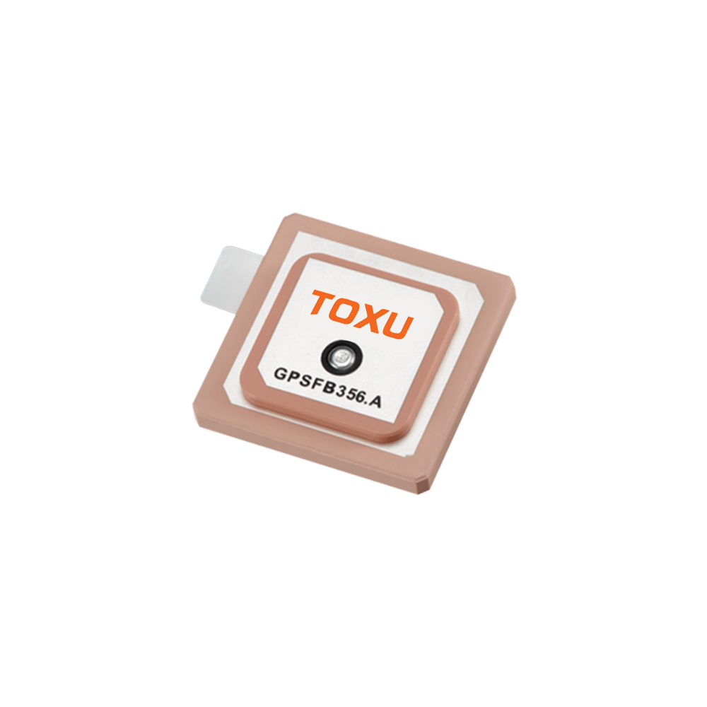
The GNSS patch antenna is a crucial component in GNSS receivers. It is responsible for receiving the weak satellite signals and converting them into electrical signals that can be processed by the receiver. High - precision custom GNSS patch antennas are designed to meet the specific requirements of various applications that demand extremely accurate positioning.
These antennas have seen a significant increase in demand in recent years. In applications like autonomous vehicles, where centimeter - level accuracy is essential for safe driving, high - precision GNSS patch antennas play a pivotal role. Precision agriculture also benefits from such antennas, as farmers can precisely manage their fields, optimizing the use of fertilizers, water, and seeds. Surveying and mapping industries rely on these antennas to create highly accurate maps and models of the Earth's surface.
The development of high - precision custom GNSS patch antennas has been driven by several factors. Technological advancements in materials science have allowed for the creation of more efficient and compact antenna designs. The miniaturization of electronic components has also contributed to the development of smaller and more lightweight antennas without sacrificing performance. Additionally, the increasing need for accurate positioning in various industries has spurred research and development in this area.
2.1 Antenna Geometry
The design of a high - precision custom GNSS patch antenna starts with its geometry. The patch itself is typically a flat, rectangular or circular conductive element. The size of the patch is carefully calculated based on the operating frequency of the GNSS system. For example, for GPS L1 band (1575.42 MHz), the patch dimensions are designed to resonate at this frequency. A common approach is to use a stacked - patch design. In a stacked - patch antenna, multiple patches are placed one above the other. This design increases the bandwidth and improves the antenna's gain. The patches are usually separated by a dielectric material, which helps in controlling the electrical properties of the antenna. The choice of dielectric material is crucial as it affects the antenna's performance. Materials with a high dielectric constant can reduce the size of the antenna, but they may also introduce more losses. Common dielectric materials used in GNSS patch antennas include ceramic, which offers a good balance between performance and size.
2.2 Ground Plane Considerations
The ground plane is an essential part of the antenna design. It serves as a reflector for the antenna's radiation pattern. In high - precision applications, the size and shape of the ground plane need to be optimized. A larger ground plane generally provides better performance in terms of gain and radiation pattern stability. However, in some applications where space is limited, a smaller ground plane may be required. In such cases, techniques like using a ground - plane - independent antenna design can be employed. These antennas are designed to be less sensitive to the size and shape of the ground plane. They often use special feeding mechanisms and parasitic elements to achieve this. The ground plane can also be designed with specific shapes, such as a circular or square shape, depending on the application requirements. The distance between the patch and the ground plane is also a critical parameter. It affects the impedance matching of the antenna and the overall radiation pattern.
2.3 Feeding Mechanisms
There are several feeding mechanisms used in high - precision custom GNSS patch antennas. One common method is the microstrip line feed. In this method, a microstrip line, which is a thin strip of conductive material on a dielectric substrate, is used to connect the patch to the receiver. The microstrip line is designed to have a specific characteristic impedance, usually 50 ohms, to match the impedance of the receiver. Another feeding mechanism is the coaxial feed. Here, a coaxial cable is used to feed the patch. The inner conductor of the coaxial cable is connected to the patch, and the outer conductor is connected to the ground plane. The choice of feeding mechanism depends on factors such as the antenna's size, performance requirements, and the manufacturing process. For example, a microstrip line feed may be more suitable for a planar antenna design, while a coaxial feed may be preferred for an antenna that needs to be connected to a cable in a more rugged environment.
2.4 Manufacturing Process
The manufacturing of high - precision custom GNSS patch antennas involves several steps. First, the conductive materials for the patch and the ground plane are selected. Copper is a commonly used material due to its excellent electrical conductivity. The dielectric material is also carefully chosen. Ceramic dielectrics are often fabricated using a sintering process, where ceramic powders are compressed and heated to form a solid structure. The patches and ground planes are then fabricated using techniques such as photolithography. In photolithography, a light - sensitive material is applied to the conductive substrate. A mask with the desired pattern of the patch or ground plane is then placed over the substrate, and ultraviolet light is shone through the mask. The exposed areas of the light - sensitive material are then removed, leaving behind the desired conductive pattern. After the patterning, the antenna is assembled, and the feeding mechanism is attached. Quality control is a crucial step in the manufacturing process. Antennas are tested for parameters such as impedance, gain, and radiation pattern to ensure they meet the high - precision requirements.
3.1 Electromagnetic Wave Reception
GNSS satellites transmit electromagnetic waves at specific frequencies. The high - precision custom GNSS patch antenna is designed to receive these waves. When an electromagnetic wave impinges on the antenna, it causes the electrons in the conductive patch to oscillate. This oscillation generates an electric current in the patch. The frequency of the received wave is related to the position of the satellite. For example, different GNSS constellations transmit at slightly different frequencies. The antenna is designed to be sensitive to these specific frequencies. The antenna's radiation pattern determines the direction from which it can receive the signals most effectively. A well - designed patch antenna has a broad radiation pattern in the horizontal plane, allowing it to receive signals from satellites in different parts of the sky. In the vertical plane, the radiation pattern is shaped to minimize interference from ground - based sources.
3.2 Signal Conversion and Transmission
Once the electromagnetic wave is received and an electric current is generated in the patch, this current needs to be converted into a signal that can be processed by the GNSS receiver. The feeding mechanism, such as a microstrip line or coaxial cable, plays a role in transmitting this current to the receiver. The impedance matching between the antenna and the receiver is crucial at this stage. If the impedance is not properly matched, a significant amount of the signal power will be reflected back to the antenna, resulting in a loss of signal strength. The antenna also contains a low - noise amplifier (LNA). The LNA is used to amplify the weak received signal before it is transmitted to the receiver. The LNA is designed to have a low noise figure, which means it adds very little noise to the signal during the amplification process. This is essential for high - precision applications, as even a small amount of added noise can degrade the accuracy of the positioning.
3.3 Multipath Mitigation
Multipath is a major challenge in GNSS signal reception. Multipath occurs when the satellite signal reaches the antenna via multiple paths, such as direct and reflected paths. These reflected signals can interfere with the direct signal, causing errors in the positioning. High - precision custom GNSS patch antennas employ several techniques to mitigate multipath. One common technique is the use of a choke ring. A choke ring is a circular structure with multiple concentric rings that are placed around the antenna. The choke ring is designed to absorb or reflect the reflected signals, reducing their impact on the direct signal. Another technique is the use of advanced signal processing algorithms in the receiver. These algorithms can analyze the received signals and identify and remove the effects of multipath. The antenna's radiation pattern can also be optimized to reduce the sensitivity to reflected signals. For example, an antenna with a narrow vertical radiation pattern is less likely to receive strong reflected signals.
4.1 Advantages
4.1.1 High Precision
The most significant advantage of high - precision custom GNSS patch antennas is their ability to provide extremely accurate positioning. In applications like surveying, they can achieve centimeter - level accuracy. This high precision is crucial for creating detailed maps and for accurately determining property boundaries. In autonomous vehicles, centimeter - level accuracy is essential for safe navigation. The antenna's ability to receive signals from multiple GNSS constellations simultaneously also contributes to its high precision. By combining signals from GPS, GLONASS, Galileo, and BeiDou, the antenna can improve the accuracy and reliability of the positioning.
4.1.2 Compact Size
Many high - precision custom GNSS patch antennas are designed to be compact. This makes them suitable for applications where space is limited, such as in small drones or wearable devices. The use of advanced materials and manufacturing techniques has enabled the miniaturization of these antennas without sacrificing performance. A compact antenna also reduces the overall size and weight of the device it is integrated into, which can be beneficial for applications that require portability.
4.1.3 Low Power Consumption
These antennas are designed to operate with low power consumption. This is important for battery - powered devices, such as mobile phones and IoT sensors. Low power consumption means that the device can operate for longer periods without recharging. The use of efficient components, such as low - noise amplifiers with low power requirements, contributes to the overall low power consumption of the antenna.
4.2 Challenges
4.2.1 Interference Susceptibility
High - precision custom GNSS patch antennas are susceptible to interference from various sources. Radio - frequency interference (RFI) from other electronic devices, such as mobile phones, Wi - Fi routers, and radar systems, can disrupt the GNSS signals. Nearby power lines and electrical equipment can also generate electromagnetic interference. To address this challenge, antennas are often designed with shielding and filtering mechanisms. Shielding materials are used to prevent external electromagnetic fields from reaching the antenna. Filters are used to remove unwanted frequencies from the received signal. However, these solutions can add complexity and cost to the antenna design.
4.2.2 Multipath Effects
As mentioned earlier, multipath is a significant challenge. Despite the use of techniques like choke rings and advanced signal processing, it is difficult to completely eliminate multipath effects, especially in urban canyons or areas with a lot of reflective surfaces. In such environments, the reflected signals can be strong enough to cause significant errors in the positioning. Improving multipath mitigation techniques is an ongoing area of research. New antenna designs and signal processing algorithms are being developed to better handle multipath in challenging environments.
4.2.3 Cost
The high - precision requirements of these antennas often result in a relatively high cost. The use of advanced materials, precise manufacturing processes, and rigorous quality control measures contribute to the cost. The cost of research and development for new antenna designs also adds to the overall cost. For mass - market applications, such as in consumer electronics, the high cost of these antennas can be a barrier to adoption. Reducing the cost while maintaining high performance is a key challenge for the industry.
5.1 Current Applications
5.1.1 Autonomous Vehicles
In the field of autonomous vehicles, high - precision custom GNSS patch antennas are essential. Autonomous cars rely on accurate positioning information to navigate safely on the roads. The centimeter - level accuracy provided by these antennas allows the vehicle to precisely determine its position relative to the road, other vehicles, and obstacles. This information is used by the vehicle's control system to make decisions such as when to accelerate, brake, or turn. The antennas also play a role in vehicle - to - everything (V2X) communication, where the vehicle exchanges information with other vehicles, infrastructure, and pedestrians.
5.1.2 Precision Agriculture
Precision agriculture has seen a significant uptake of high - precision GNSS patch antennas. Farmers use these antennas to precisely control agricultural machinery, such as tractors and sprayers. The accurate positioning allows for variable - rate application of fertilizers, pesticides, and seeds. This means that farmers can apply these inputs only where they are needed, reducing waste and environmental impact. The antennas also help in mapping the fields, identifying areas with different soil conditions, and monitoring crop growth.
5.1.3 Surveying and Mapping
Surveying and mapping industries rely heavily on high - precision GNSS patch antennas. Land surveyors use these antennas to accurately measure distances, angles, and elevations. This information is used to create detailed maps of the Earth's surface, which are used in various applications, including urban planning, construction, and environmental monitoring. The antennas are also used in aerial and satellite mapping, where they help in precisely georeferencing the images.
5.2 Future Trends
5.2.1 Integration with Other Technologies
In the future, high - precision custom GNSS patch antennas are likely to be integrated with other technologies. For example, they may be combined with inertial navigation systems (INS) to provide even more accurate positioning. INS can provide short - term accurate positioning when GNSS signals are temporarily unavailable, such as in tunnels or dense urban areas. The combination of GNSS and INS can create a more robust and reliable positioning system. There is also a trend towards integrating GNSS antennas with 5G and future wireless communication technologies. This integration can enable new applications, such as real - time traffic monitoring and smart city management.
5.2.2 Development of New Antenna Designs
Research is ongoing to develop new antenna designs that offer even better performance. One area of focus is the development of antennas with higher gain and broader bandwidth. Higher gain antennas can receive weaker signals, improving the performance in areas with poor satellite visibility. Broader bandwidth antennas can support more GNSS frequency bands, further enhancing the accuracy and reliability of the positioning. New materials, such as metamaterials, are also being explored for antenna design. Metamaterials can be engineered to have unique electromagnetic properties, which can be used to create antennas with improved performance.
5.2.3 Expansion into New Markets
As the performance of high - precision custom GNSS patch antennas improves and the cost decreases, there is potential for expansion into new markets. For example, in the healthcare industry, these antennas could be used in wearable devices for patient tracking and monitoring. In the logistics industry, they could be used to improve the tracking of goods in transit. The growth of the Internet of Things (IoT) also presents opportunities for these antennas, as more and more devices require accurate positioning information.
6. Conclusion
High - precision custom GNSS patch antennas have emerged as a critical technology in various industries. Their ability to provide accurate positioning, combined with their compact size and low power consumption, makes them suitable for a wide range of applications. The design and construction of these antennas involve careful consideration of factors such as geometry, ground plane, feeding mechanisms, and manufacturing processes. The working principles of these antennas, including electromagnetic wave reception, signal conversion, and multipath mitigation, are complex and rely on advanced technologies.
Despite the many advantages, there are also challenges associated with these antennas, such as interference susceptibility, multipath effects, and cost. However, ongoing research and development efforts are focused on addressing these challenges. The future of high - precision custom GNSS patch antennas looks promising, with trends such as integration with other technologies, development of new antenna designs, and expansion into new markets. As these trends continue to unfold, these antennas are likely to play an even more significant role in shaping the future of navigation and positioning - based applications.

 86 0755 2819 9597
Lucy Yang | lucy.y@toxutech.com
Nicole Li | nicole@toxutech.com
Dotty Zhao | sales04@toxutech.com
Global Business Director / Sales Team / Global Operations


 En
En Cn
Cn Korean
 Home >


