

-
Products -PCBA Manufacturing RF Connectors RF Cable Assemblys Embedded Antennas External Antennas Positioning Chips and Modules
RF Connectors

RF Cable Assemblys
Embedded Antennas
External Antennas
Positioning Chips and Modules


 Language


Language


In the realm of high-precision geospatial measurement, where reliable signal reception is the foundation of accuracy, high-gain RTK surveying antennas stand out as critical tools. These specialized antennas are engineered to amplify weak satellite signals, enabling Real-Time Kinematic (RTK) systems to maintain centimeter-level precision even in signal-challenged environments such as dense forests, urban canyons, or remote mountainous regions. Unlike standard RTK antennas with moderate gain (typically 5–8 dBi), high-gain models deliver gain values ranging from 10–15 dBi, a significant boost that transforms the performance of RTK systems in areas where satellite signals are attenuated or obstructed.
Core Design Features for High-Gain Performance
The ability of high-gain RTK surveying antennas to amplify signals without introducing excessive noise stems from several key design innovations:
Directional Radiation Patterns with Narrow Beamwidth: High-gain antennas achieve their amplified signal reception through a focused radiation pattern with a narrower beamwidth in the vertical plane (typically 30–60 degrees) compared to standard antennas. This narrow beam concentrates energy toward the sky, increasing the antenna’s sensitivity to satellite signals while reducing the pickup of unwanted noise from the horizon and ground. The horizontal radiation pattern remains sufficiently broad (360 degrees) to ensure coverage of satellites across all azimuth angles, maintaining the ability to track multiple satellites simultaneously.
Multi-Element Array Configuration: Unlike single-patch antennas, high-gain models often use a phased array of radiating elements. These arrays consist of multiple interconnected patches arranged in a grid or circular pattern, each contributing to the overall gain through constructive interference. The phases of the signals received by each element are adjusted (via a phase shifter) to reinforce signals from satellite directions while canceling out noise from other angles. This array design not only boosts gain but also allows for beam steering—an advanced feature where the radiation pattern can be dynamically adjusted to track satellites as they move across the sky.
Dual-Frequency and Multi-Constellation Compatibility: To maintain RTK’s centimeter-level accuracy while amplifying signals, high-gain antennas are designed to support multiple GNSS constellations (GPS, GLONASS, Galileo, BeiDou) and dual frequency bands (e.g., L1/L2, L1/L5). This multi-band capability ensures that the antenna can amplify signals across different frequencies, enabling the receiver to correct for ionospheric delays—a critical factor in preserving accuracy. The antenna’s filtering circuitry is optimized to prevent cross-talk between frequency bands, ensuring that amplification is applied uniformly without distorting the signal characteristics needed for precise phase measurements.
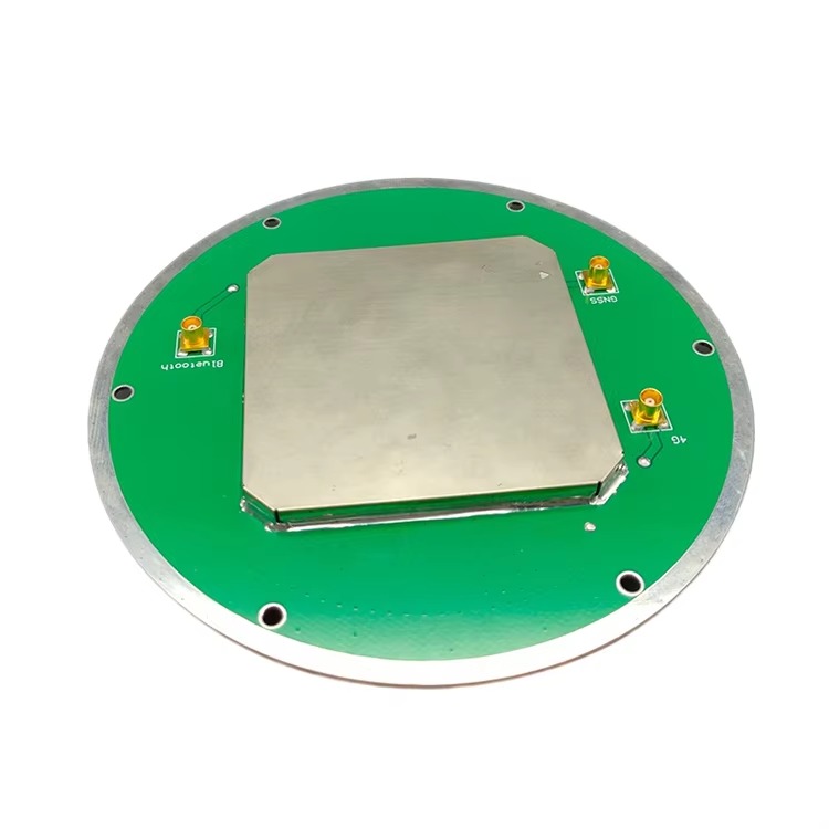
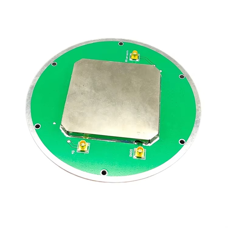
Construction Components
The physical construction of high-gain RTK surveying antennas combines precision engineering with robust materials to deliver both performance and durability:
Radiating Elements: The core of the antenna is a phased array of planar patches made from high-conductivity materials such as gold-plated copper or silver. Each patch is etched onto a low-loss ceramic substrate with a high dielectric constant (εr > 25), which allows for compact element design while enhancing radiation efficiency. The patches are interconnected via microstrip lines, which distribute signals across the array while maintaining controlled phase relationships. The number of elements in the array (typically 4–16) directly influences gain—more elements result in higher gain but increase size and complexity.
Feed Network and Phase Shifters: The feed network distributes the received signals from the array elements to the Low-Noise Amplifier (LNA) while maintaining the correct phase relationships. In beam-steering models, solid-state phase shifters adjust the phase of each element’s signal, allowing the antenna to dynamically focus its radiation pattern on specific satellites. These phase shifters are controlled by the RTK receiver, which uses ephemeris data to predict satellite positions and optimize the beam direction.
Low-Noise Amplifier (LNA) with Gain Control: The LNA in high-gain antennas is designed to work in tandem with the array, providing additional amplification (typically 20–30 dB) while maintaining an extremely low noise figure (<0.7 dB). Unlike fixed-gain LNAs, these models often include automatic gain control (AGC), which adjusts amplification levels based on signal strength. This prevents over-amplification of strong signals (which can cause distortion) while ensuring weak signals are boosted sufficiently for processing. The LNA is positioned as close to the radiating elements as possible to minimize signal loss before amplification.
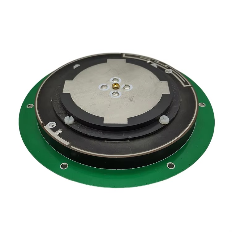
Rugged Enclosure with Optimized Radome: The antenna is housed in a weatherproof enclosure with an IP67 or IP68 rating, ensuring operation in extreme temperatures (-40°C to +70°C), heavy rain, and dust. The radome—made from fiberglass-reinforced composite or low-loss plastic—is engineered to be transparent to GNSS frequencies, with a dielectric loss of <0.02 at 1.5 GHz. Its shape is aerodynamically optimized to reduce wind resistance during fieldwork and may include a hydrophobic coating to repel water, preventing signal attenuation from moisture buildup.
Ground Plane and Shielding: A large, thick (≥4 mm) aluminum ground plane serves as a reflective surface, enhancing gain by bouncing downward-traveling signals back toward the radiating elements. It also acts as a shield against electromagnetic interference (EMI) from the surveying equipment or nearby power lines. For applications requiring minimal weight (e.g., drone mounting), the ground plane may be fabricated from carbon fiber-reinforced polymer with a conductive coating, balancing durability and weight reduction.
Core Design Features for Centimeter-Level Accuracy
To achieve centimeter-level precision, these antennas incorporate design elements that minimize errors at every stage of signal processing:
Dual-Frequency and Multi-Constellation Support: Centimeter-level RTK antennas are designed to receive signals from multiple GNSS constellations (GPS, GLONASS, Galileo, BeiDou) and at least two frequency bands per constellation (e.g., L1/L2 for GPS). This dual-frequency capability allows the receiver to model and correct ionospheric delays, which are frequency-dependent and can introduce errors of several meters if uncompensated. By combining data from multiple constellations, the antenna ensures a robust satellite lock even in challenging environments, reducing the risk of accuracy degradation due to signal loss.
Ultra-Low Phase Center Variation (PCV): The phase center—the point where satellite signals are electrically processed—must remain stable across all satellite angles and environmental conditions. Centimeter-level antennas achieve PCV as low as 0.5–1 millimeter, a level of stability achieved through precision manufacturing of the radiating element and ground plane. Manufacturers perform rigorous calibration to map PCV across the antenna’s entire field of view, providing correction models that the receiver uses to eliminate residual errors. This calibration is often done in anechoic chambers with robotic positioners to ensure accuracy.
Highly Directional Radiation Patterns with Low Sidelobes: The antenna’s radiation pattern is optimized to focus on satellites while minimizing interference from ground-based reflections. This is achieved through a hemispherical pattern with high gain (8–12 dBi) in the upper hemisphere and suppressed sidelobes, which reduces multipath signals from below. The radiating element is designed to reject signals coming from angles below the horizon, where reflections from buildings, trees, or terrain are most common.
Construction Components
The physical construction of centimeter-level RTK antennas combines advanced materials and precision engineering to maintain performance in harsh field conditions:
Radiating Element: The core signal-capturing component is a multi-layer planar patch array made from high-purity copper or gold-plated copper. These patches are etched onto a low-loss ceramic substrate with a high dielectric constant (εr > 20), allowing for compact design while maintaining high efficiency. The patch geometry is optimized using electromagnetic simulation software to ensure resonance at target frequencies and uniform performance across all supported bands. Each patch in the array is tuned to a specific frequency, with isolation between patches to prevent cross-talk.
Ground Plane: A thick (≥3 mm) aluminum or brass ground plane serves as both a reflective surface and an EMI shield. The ground plane is larger than the radiating element (typically 20–30 cm in diameter) to minimize edge diffraction, which can distort the radiation pattern. For applications requiring minimal weight (e.g., drone mounting), the ground plane may be made from lightweight alloys like aluminum 6061-T6, with reinforcing ribs to maintain rigidity.
Low-Noise Amplifier (LNA) with Advanced Filtering: The LNA is positioned within 1–2 cm of the radiating element to minimize signal loss before amplification. It features a noise figure of <0.8 dB, ensuring that weak signals (as low as -165 dBm) are amplified without introducing significant noise. The LNA is paired with a multi-stage band-pass filter that rejects out-of-band interference from cellular networks (4G/5G), Wi-Fi, and radar systems. Some antennas include a second-stage amplifier near the connector to compensate for cable losses in long runs.
Hermetically Sealed Enclosure: The antenna is encased in a rugged, weatherproof enclosure with an IP68 rating, ensuring operation in submersion up to 2 meters for 30 minutes. The radome is made from fiberglass-reinforced polypropylene or PEEK, materials chosen for their low dielectric loss at GNSS frequencies (<0.01 at 1.5 GHz) and resistance to UV radiation and chemical corrosion. The enclosure includes a pressure equalization valve to prevent damage from temperature-induced air expansion or contraction.
Low-Loss Cable and Precision Connectors: The antenna is connected to the receiver via a low-loss coaxial cable (e.g., LMR-400 or equivalent) with a attenuation of <4 dB/10m at 1.5 GHz. The cable is jacketed in polyurethane for flexibility and resistance to oil, water, and abrasion. Connectors are precision-machined TNC or SMA types with gold plating to ensure low contact resistance and weatherproof seals (O-rings made from EPDM rubber). Some antennas include a built-in bias tee to power the LNA via the coaxial cable, simplifying installation.
High-gain RTK surveying antennas operate on the fundamental principle of constructive interference to amplify satellite signals, while integrating seamlessly with RTK systems to deliver precise positioning. Here’s a detailed breakdown of their operation:
Signal Capture and Amplification via Array Gain: The phased array of radiating elements captures GNSS signals from multiple satellites. Each element receives the signal at a slightly different phase, depending on the satellite’s position. The feed network combines these signals in a way that reinforces (constructive interference) signals from the desired satellite directions and cancels out (destructive interference) signals from other angles, such as ground reflections. This process naturally amplifies the desired signals, contributing to the antenna’s high gain.
Low-Noise Amplification: The combined signal from the array is passed to the LNA, which amplifies it by 20–30 dB. The LNA’s low noise figure ensures that the amplified signal retains a high signal-to-noise ratio (SNR), critical for the RTK receiver to resolve carrier-phase ambiguities. In beam-steering models, the phase shifters dynamically adjust the array’s radiation pattern to track satellites as they move, ensuring that the maximum gain is always directed toward the available satellites.
Frequency Filtering and Signal Conditioning: After amplification, the signal passes through band-pass filters that isolate the desired GNSS frequencies (e.g., L1 and L2), rejecting interference from cellular networks, Wi-Fi, and other radio sources. This filtering is essential because high gain can amplify noise and interference alongside the desired signals, degrading performance. The filtered signals are then conditioned to match the input requirements of the RTK receiver, with impedance matching to ensure maximum power transfer.
RTK Correction Integration: Like standard RTK systems, high-gain antennas work with a base station that transmits error corrections. The amplified and filtered signals from the antenna are processed by the rover receiver, which uses the base station corrections to adjust for ionospheric, tropospheric, and satellite clock errors. The high SNR provided by the antenna enables the receiver to resolve integer ambiguities more quickly and reliably, even when only a few satellites are visible.
Dynamic Performance Optimization: In beam-steering models, the receiver continuously updates the antenna’s phase shifters based on real-time satellite tracking data. This ensures that the radiation pattern is always focused on the strongest available satellites, maximizing signal strength and minimizing interference. For example, in an urban canyon with only 3–4 visible satellites, the antenna can direct its gain toward those satellites, ensuring that their signals are strong enough for centimeter-level positioning.
Advantages of High-Gain RTK Surveying Antennas
High-gain RTK surveying antennas offer unique benefits that make them indispensable in challenging environments:
Superior Signal Reception in Weak-Signal Areas: The most significant advantage is their ability to amplify weak signals, enabling RTK positioning in areas where standard antennas fail. In dense forests, for example, tree canopies can attenuate satellite signals by 10–20 dB; high-gain antennas compensate for this loss, allowing surveyors to map terrain or conduct ecological studies without sacrificing accuracy. Similarly, in urban canyons, where tall buildings block most satellites, the antenna’s focused gain ensures that signals from the few visible satellites are strong enough for reliable RTK operation.
Extended Range in Remote Locations: In remote areas with limited satellite visibility (e.g., mountain valleys), high-gain antennas can capture signals from low-elevation satellites that would otherwise be too weak for standard equipment. This extends the effective range of RTK systems, reducing the need for additional base stations and enabling surveys in previously inaccessible regions. For example, mining operations in deep valleys can use high-gain antennas to maintain centimeter-level accuracy, improving safety and efficiency.
Faster Ambiguity Resolution: The high SNR provided by these antennas accelerates the RTK receiver’s ability to resolve integer ambiguities—the process of determining the exact number of carrier-wave cycles between the satellite and receiver. In weak-signal conditions, standard antennas may take 5–10 minutes to resolve ambiguities, while high-gain models can achieve this in 1–2 minutes, reducing field time and improving productivity.
Enhanced Reliability in Dynamic Environments: Beam-steering capabilities (in advanced models) allow the antenna to adapt to changing conditions, such as passing clouds or moving obstructions (e.g., construction cranes). By dynamically focusing on the strongest available satellites, the antenna maintains a stable lock, preventing drops in accuracy that can occur with fixed-pattern antennas when signals are temporarily blocked.
Compatibility with Existing RTK Infrastructure: High-gain RTK antennas are designed to work seamlessly with standard RTK receivers and base stations, requiring no modifications to existing workflows. This compatibility allows surveying firms to upgrade their equipment incrementally, leveraging their existing investment in RTK systems while extending their capabilities into more challenging environments.
Challenges and Limitations
Despite their advantages, high-gain RTK surveying antennas face several limitations that must be considered:
Increased Sensitivity to Multipath Interference: The same directional gain that amplifies satellite signals can also amplify multipath signals—reflections from buildings, trees, or the ground. In urban environments, multipath can introduce errors of 5–10 cm, as the antenna cannot distinguish between direct and reflected signals. While advanced receivers use algorithms to mitigate multipath, high-gain antennas require careful placement (e.g., away from large reflective surfaces) to minimize this effect, adding complexity to fieldwork.
Narrow Beamwidth Trade-Off: The narrow vertical beamwidth that enables high gain also makes the antenna more sensitive to orientation. Even small tilts (5–10 degrees) can cause signal strength to drop significantly, as the beam moves off the satellite’s position. This requires precise mounting on surveying poles or vehicles, with leveling mechanisms to ensure the antenna remains upright. In dynamic applications (e.g., moving drones), maintaining optimal orientation is challenging and may require gyroscopic stabilization systems.
Larger Size and Weight: The phased array design and additional elements needed for high gain result in larger, heavier antennas compared to standard models. A typical high-gain RTK antenna weighs 1.5–3 kg, nearly twice the weight of a standard antenna, making it less suitable for backpack-mounted surveys or small drones with limited payload capacity. This weight can also increase fatigue for surveyors working long hours in the field.
Higher Cost and Complexity: High-gain RTK antennas are significantly more expensive than standard models, with prices ranging from \(3,000–\)15,000, depending on features like beam steering. This cost is driven by the complex phased array design, precision manufacturing, and advanced electronics. Additionally, operating beam-steering models requires specialized training to configure and calibrate the antenna, limiting accessibility for small surveying firms.
Power Consumption: The phased array, phase shifters, and high-performance LNA consume more power than standard antennas, typically 2–3 times the current (150–300 mA at 5V). This increased power demand can shorten battery life in portable RTK systems, requiring larger batteries or more frequent recharging—an inconvenience in remote areas without power access.
Applications and Future Trends
High-gain RTK surveying antennas are deployed in scenarios where signal strength is the limiting factor for precision positioning:
Forestry and Environmental Surveying: In dense forests, where tree canopies block or attenuate satellite signals, high-gain antennas enable accurate mapping of terrain, vegetation, and wildlife habitats. They are used in conservation projects to monitor deforestation rates, measure carbon sequestration, and map watersheds, providing data that informs sustainable land management.
Urban Infrastructure Surveys: In cities with tall buildings, high-gain antennas maintain RTK accuracy for projects such as utility mapping, road construction, and building deformation monitoring. They allow surveyors to work in narrow streets or between skyscrapers, where standard antennas would struggle to maintain a sufficient number of satellite locks. For example, monitoring the movement of skyscrapers during construction requires centimeter-level precision, even in the shadow of adjacent buildings.
Mining and Quarrying: In deep open-pit mines or narrow valleys, high-gain antennas capture signals from low-elevation satellites that clear the mine walls. They are used to guide drilling equipment, monitor slope stability, and map ore deposits, ensuring safe and efficient operations. The ability to maintain RTK accuracy in these challenging environments reduces the need for expensive ground-based positioning systems.
Precision Agriculture in Covered Environments: In greenhouse agriculture or regions with dense cloud cover, high-gain antennas amplify weak signals to guide autonomous tractors, map soil variability, and monitor crop health. They ensure that precision farming techniques—such as variable-rate fertilization—can be applied even in conditions that would degrade the performance of standard RTK systems.
Drone-Based Surveying in Complex Terrain: Drones equipped with high-gain antennas are used to map rugged terrain, such as mountain ranges, coastal cliffs, or volcanic areas. The antenna’s ability to amplify signals allows the drone to maintain centimeter-level positioning even when flying at low altitudes or near vertical surfaces, enabling detailed 3D modeling of hard-to-reach areas.
Future Trends
The development of high-gain RTK surveying antennas is shaped by advances in materials, artificial intelligence, and satellite technology:
AI-Optimized Beam Steering: Machine learning algorithms will enable antennas to predict and adapt to signal blockages in real time. By analyzing historical data and current satellite positions, AI systems will dynamically adjust the radiation pattern to avoid multipath sources and focus on the most reliable satellites, reducing errors in urban and forested environments.
Metamaterial Arrays: Metamaterials—engineered materials with unique electromagnetic properties—will enable smaller, lighter high-gain antennas. These materials can manipulate electromagnetic waves to achieve high gain with fewer elements, reducing size and weight by 30–50% compared to traditional arrays. This will expand their use in small drones and portable surveying equipment.
Integration with LEO Satellite Constellations: Low Earth Orbit (LEO) satellite constellations (e.g., Starlink, OneWeb) will provide stronger, more frequent signals than traditional GNSS satellites, complementing the gain of high-gain antennas. This combination will improve performance in polar regions and deep canyons, where traditional satellite coverage is limited.
Multi-Band, Multi-Constellation Optimization: Future high-gain antennas will support an even broader range of frequencies, including new GNSS bands such as GPS L1C, Galileo E6, and BeiDou B3. This will enable better mitigation of atmospheric errors and interference, further enhancing accuracy in challenging environments.
Energy Harvesting and Power Efficiency: Advances in low-power electronics and energy harvesting (e.g., solar-powered LNAs) will reduce the power consumption of high-gain antennas, extending battery life in portable applications. This will make them more practical for long-duration surveys in remote areas.
Conclusion
High-gain RTK surveying antennas represent a critical innovation in geospatial measurement, enabling centimeter-level precision in environments where standard equipment would fail. Their ability to amplify weak satellite signals through phased array design, directional radiation patterns, and advanced signal processing has transformed the scope of RTK applications, from forestry and urban infrastructure to mining and drone surveying. By overcoming the limitations of signal attenuation and obstruction, these antennas have expanded the reach of high-precision positioning technology, making it possible to collect accurate data in previously inaccessible locations.
While challenges such as multipath sensitivity, size, and cost persist, ongoing advancements in AI, metamaterials, and satellite technology are addressing these limitations. Future high-gain antennas will be smaller, more efficient, and smarter, with the ability to adapt dynamically to changing signal conditions. As a result, they will play an increasingly vital role in supporting industries that rely on

 86 0755 2819 9597
Lucy Yang | lucy.y@toxutech.com
Nicole Li | nicole@toxutech.com
Dotty Zhao | sales04@toxutech.com
Global Business Director / Sales Team / Global Operations


 En
En Cn
Cn Korean
 Home >


