

-
Products -PCBA Manufacturing RF Connectors RF Cable Assemblys Embedded Antennas External Antennas Positioning Chips and Modules
RF Connectors

RF Cable Assemblys
Embedded Antennas
External Antennas
Positioning Chips and Modules


 Language


Language


The evolution of Global Navigation Satellite Systems (GNSS) has moved beyond reliance on a single constellation. Modern high-precision applications demand more satellites, better geometry, and increased robustness, leading to the rise of multi-constellation solutions. At the heart of this capability is the GPS+GLONASS Multi-System RTK Antenna, a sophisticated device engineered to be the critical first stage in achieving real-time, centimeter-level accuracy. This antenna is not a mere accessory; it is the foundational sensor that enables a new era of precision by simultaneously harnessing the power of American and Russian satellite networks.
A GPS+GLONASS Multi-System RTK antenna is a specialized type of GNSS antenna designed explicitly for use in Real-Time Kinematic (RTK) and other carrier-phase-based positioning systems. Its name defines its core purpose:
GPS+GLONASS: It is designed to receive signals from both the American GPS (Global Positioning System) and the Russian GLONASS (Global'naya Navigatsionnaya Sputnikovaya Sistema) satellite constellations. This dual-system capability is its defining feature, doubling the number of available satellites compared to using GPS alone.
Multi-System: While focusing on GPS and GLONASS, most modern antennas of this type are also capable of receiving signals from other constellations like Galileo (EU) and BeiDou (China), making them truly "multi-GNSS" and future-proof.
RTK: This signifies that the antenna is engineered for the highest standards of precision required for RTK positioning. RTK relies on measuring the phase of the satellite's carrier wave itself, a process that demands exceptional signal integrity, phase stability, and multipath mitigation from the antenna.
The primary driver for this technology is the insatiable demand for improved performance in precision applications. Using a single constellation like GPS can provide adequate satellite coverage in open-sky conditions. However, in challenging environments such as urban canyons, under tree canyons, or in mountainous terrain, the view to the sky is often obstructed. Satellites are frequently blocked, leading to poor satellite geometry (high Position Dilution of Precision, or PDOP) and, in worst-case scenarios, an insufficient number of satellites to compute a fixed RTK solution. By incorporating GLONASS, the available satellite count instantly increases from ~30 GPS satellites to over 50 satellites, dramatically improving availability and reliability.
However, simply receiving more signals is not enough. An RTK-grade antenna must do so with impeccable quality. Unlike a standard navigation antenna, an RTK antenna is characterized by several key attributes:
Precision Phase Center Stability: The electrical phase center of the antenna must be extremely stable and well-defined. Any movement of this point with satellite elevation or azimuth introduces error into the precise carrier-phase measurements. RTK antennas are meticulously calibrated to model and correct for these variations.
Advanced Multipath Mitigation: Multipath error, caused by signals reflecting off the ground, buildings, or other objects, is the nemesis of high-precision GNSS. RTK antennas incorporate specialized designs, such as choke rings or advanced ground planes, to suppress these reflected signals aggressively.
Multi-Frequency Support: Modern RTK operates on multiple frequencies (e.g., GPS L1/L2/L5, GLONASS L1/L2/L3) to correct for atmospheric delays. The antenna must be efficient across all these bands.
Right-Hand Circular Polarization (RHCP) Purity: It must perfectly match the polarization of the direct satellite signals while rejecting the reversed polarization of reflected signals.
Therefore, a GPS+GLONASS Multi-System RTK antenna is a high-performance instrument designed to provide a robust, clean, and stable signal feed from the largest possible number of satellites to a sophisticated RTK receiver. It is the indispensable gateway for applications where accuracy, reliability, and availability cannot be compromised, forming the reliable backbone of modern surveying, construction, agriculture, and autonomous machine control.
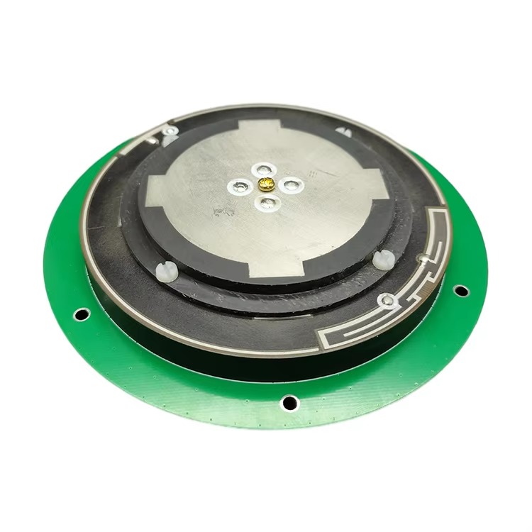
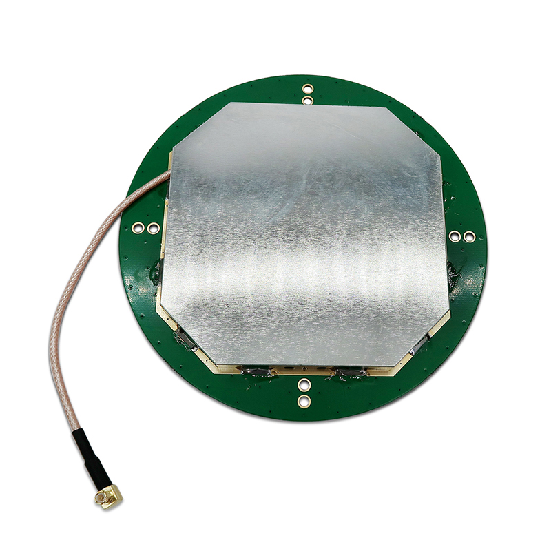
The design and construction of a GPS+GLONASS Multi-System RTK antenna is a complex exercise in electromagnetic engineering, requiring a careful balance between wide bandwidth performance, phase stability, and physical robustness. Every component is optimized to handle the distinct signals from multiple satellite systems with utmost fidelity.
1. The Radiating Element: The Wideband Heart
The core of the antenna is the radiating element, which must be capable of operating efficiently across multiple frequency bands. Unlike a single-band antenna, this element is a wideband or multi-resonant design.
Frequencies: It must cover at a minimum:
GPS L1: 1575.42 MHz
GPS L2: 1227.60 MHz
GLONASS L1: ~1602 MHz (with a small spread due to its FDMA nature)
GLONASS L2: ~1246 MHz (also FDMA)
Modern antennas also include:
GPS L5: 1176.45 MHz
GLONASS L3: 1202.025 MHz
Galileo and BeiDou B1/B2 signals.
Design Techniques: Achieving this is typically done with a stacked-patch or coupled-patch design. Multiple patch elements of slightly different sizes are layered on top of each other, each tuned to a primary frequency band (e.g., a larger patch for L2 and a smaller one for L1). Sophisticated feeding mechanisms excite these patches to create multiple resonant points across the required spectrum. The element is fabricated on a low-loss dielectric substrate to minimize signal loss.
2. The Ground Plane and Multipath Mitigation
The ground plane is a critical part of the antenna system. For RTK applications, it is not merely a passive reflector but an active component for performance enhancement.
Solid Ground Plane: A finite-sized, circular ground plane is standard. Its size is carefully chosen to optimize the antenna's radiation pattern, ensuring good gain at low elevations while providing a base level of shielding from ground-borne multipath.
Choke Ring Technology: High-end RTK antennas incorporate an integrated choke ring structure. These concentric corrugated rings surrounding the radiator act as a high-impedance surface. They are designed to be a quarter-wavelength deep at the target frequency, which prevents surface currents from flowing. This effectively "chokes" or rejects signals arriving at low angles—the primary direction of multipath reflections. While adding bulk, choke rings offer the best-in-class multipath suppression.
3. The Feed Network and Impedance Matching
The signal from the radiating patch is collected by a feed network. This network must efficiently combine the signals from the different resonant modes of the patch(es) and present a consistent 50-ohm impedance to the output across all frequency bands. This is a significant challenge due to the wide frequency separation (e.g., between L2 at ~1220 MHz and L1 at ~1575 MHz). Complex matching networks are designed into the substrate to ensure smooth performance across the entire bandwidth.
4. Low-Noise Amplifier (LNA)
Immediately following the radiating element is a Low-Noise Amplifier (LNA). This active component is crucial. Its primary functions are:
Gain: To amplify the extremely weak signals received from the satellites (on the order of -130 dBm) to a level strong enough to travel down the coaxial cable to the receiver without being degraded by cable loss.
Low Noise Figure: To accomplish this amplification while adding the absolute minimum amount of electronic noise of its own. A great LNA has a high gain and an exceptionally low noise figure (e.g., <2 dB), preserving the precious signal-to-noise ratio (SNR).
Filtering: The LNA stage often includes bandpass filtering to reject strong out-of-band interference from cellular, WiFi, and other radio services that could overload the receiver.
5. Phase Center Calibration
The most critical aspect of an RTK antenna's construction is the stability of its Phase Center. The physical point of measurement (Antenna Reference Point) is not where the signal is electrically received. The Phase Center Offset (PCO) and Phase Center Variation (PCV) must be precisely known and stable.
Design for Stability: The antenna is designed to be electromagnetically symmetrical to minimize PCV—the change in phase center with satellite elevation and azimuth.
Calibration: Each antenna model is painstakingly calibrated in an anechoic chamber. This process maps the precise PCO and PCV for every frequency. This calibration data is applied in the post-processing software or receiver firmware to correct the raw measurements, ensuring they are all referenced to a single, stable virtual point.
6. Housing and Environmental Sealing
The entire assembly is housed in a rugged, environmental radome, typically made from high-grade UV-stable plastic (e.g., polycarbonate). The housing is sealed to IP67 or higher standards to prevent moisture ingress, which could detune the antenna and cause corrosion. A standard geodetic mounting thread (e.g., 5/8"-11) is integrated into the base for secure attachment to tripods, poles, or permanent monuments.
In summary, the construction of a multi-system RTK antenna is a holistic integration of wideband radiators, sophisticated electronics, and precision mechanical design, all aimed at delivering a pure, stable, and powerful signal from every visible satellite across multiple constellations.
The operation of a GPS+GLONASS Multi-System RTK antenna is a sophisticated process of signal capture, purification, and preparation. It functions not as a simple collector, but as a high-fidelity filter and pre-amplifier, executing a precise sequence of steps to ensure the receiver receives the cleanest possible data for centimeter-level positioning.
1. Dual-Signal Reception and Polarization Matching
The antenna's radiating element is continuously illuminated by signals from dozens of satellites from multiple constellations. Each satellite transmits Right-Hand Circularly Polarized (RHCP) signals. The antenna's patch element is specifically designed to be sensitive only to RHCP signals. This provides the first layer of defense against multipath, as signals reflected off surfaces typically undergo a polarization shift towards Left-Hand Circular Polarization (LHCP), which the antenna inherently rejects.
2. Wideband Resonance and Frequency Separation
The multi-resonant patch element is simultaneously excited by signals across a wide frequency spectrum—from ~1160 MHz (L5) to ~1610 MHz (GLONASS L1). The patch's design allows it to resonate efficiently at these disparate frequencies. The energy from each frequency band is coupled out through the feed network. The antenna itself does not separate the signals by constellation; it simply captures all RHCP energy within its designed bandwidth and passes it along. The task of distinguishing GPS L1 from GLONASS L1 from Galileo E1 is handled by the receiver's digital signal processing correlators.
3. Multipath Mitigation: Rejecting the Deceivers
Multipath signals, which have traveled a longer path than the direct line-of-sight signal, are a primary source of error. The antenna attacks this problem on two fronts:
Polarization Discrimination: As mentioned, the RHCP design rejects most LHCP reflected signals.
Radiation Pattern Control: The antenna's ground plane (especially a choke ring) shapes its radiation pattern to have high gain towards the zenith and very low gain towards and below the horizon. Since multipath signals typically arrive at low elevation angles, they are attenuated by the antenna's pattern. The choke rings make this attenuation exceptionally effective by preventing the antenna from "seeing" anything below the horizontal plane.
4. Low-Noise Amplification: Preserving the Signal-to-Noise Ratio
The signals captured by the patch are incredibly weak, often buried below the thermal noise floor. They are immediately passed to the Low-Noise Amplifier (LNA). The LNA's critical job is to boost the amplitude of all signals within the passband (both desired GNSS signals and unwanted noise) by a factor of 30-40 dB. The quality of an LNA is defined by its Noise Figure—a measure of how much additional noise it adds to the signal. A low noise figure (e.g., 1.5 dB) means the LNA amplifies the signal while degrading the Signal-to-Noise Ratio (SNR) only marginally. This amplified signal is now strong enough to withstand the inevitable losses of the transmission cable.
5. Ensuring Phase Stability for Carrier-Phase Tracking
The entire design is geared towards one goal: enabling precise carrier-phase measurement. The receiver measures the phase of the carrier wave itself, which allows for millimeter-level accuracy. For this to work, the electrical path length from the satellite to the receiver must be known and stable. The antenna is the first point in this chain.
Stable Electrical Point: The antenna is designed to have a Phase Center that does not move. Whether a satellite is directly overhead or near the horizon, the effective point of measurement should be the same.
Calibration Correction: In reality, there are slight variations (Phase Center Variations - PCV). The pre-determined calibration model for that specific antenna model is applied within the processing software. This software correction effectively "moves" all measurements to a single, stable virtual point, ensuring that phase measurements from different satellites are consistent and comparable. This is absolutely mandatory for resolving integer ambiguities in RTK processing.
6. The Role in RTK: Base and Rover Coordination
In an RTK system, a base station antenna is set up over a known point. A rover antenna moves to unknown points. Both antennas must receive signals from the same set of satellites. The multi-system capability dramatically increases the probability that both base and rover are tracking a common set of satellites, which is critical for generating and maintaining a fixed integer solution. Furthermore, for the differential corrections to be valid, the phase center characteristics of the base and rover antennas must be known. Using antennas with the same calibration model (or carefully accounting for different models) is essential for achieving the highest accuracy.
In essence, the antenna works by acting as a spatially and polarimetrically selective filter, capturing the desired signals, ruthlessly suppressing noise and multipath, amplifying the result without corruption, and providing a stable phase reference—all across a wide range of frequencies from multiple satellite systems simultaneously.
Adopting a GPS+GLONASS Multi-System RTK antenna offers a transformative set of advantages for high-precision positioning, but these benefits are accompanied by significant technical and practical challenges that must be understood and managed.
Advantages:
Increased Satellite Availability and improved Geometry: This is the foremost advantage. By doubling the number of available satellites, the system significantly improves satellite geometry, leading to a lower Position Dilution of Precision (PDOP). This directly translates to higher potential accuracy and, more importantly, greater reliability of the position solution.
Enhanced Reliability and Availability in Challenging Environments: In urban canyons, under dense tree cover, or in mountainous terrain, the view to parts of the sky is obstructed. With only GPS, these obstructions can lead to insufficient satellites for an RTK fix. With GPS+GLONASS, the odds of having enough satellites from at least one constellation in a clear patch of sky are vastly improved, reducing downtime and increasing productivity.
Faster Time-to-First-Fix (TTFF) and Re-acquisition: A greater number of satellites allows the receiver to calculate a position more quickly from a cold start. Furthermore, if the rover loses lock (e.g., driving under a bridge), the increased satellite count enables it to re-acquire a fixed RTK solution much faster upon regaining signal.
Improved Robustness and Integrity: With more measurements available, the system can better self-diagnose problems. It can detect and exclude faulty measurements from a single satellite without jeopardizing the entire solution, leading to a more robust and trustworthy position output.
Future-Proofing: Investing in a multi-GNSS antenna prepares the user for the full operational capabilities of all global constellations (including Galileo and BeiDou), ensuring the equipment remains viable and effective for years to come.
Challenges:
Increased Cost and Complexity: The design and manufacturing of a wideband, high-performance antenna with a low-noise amplifier and rigorous calibration are inherently more complex and expensive than a single-band GPS antenna. This cost is passed on to the end-user.
Calibration and Inter-System Bias: This is a critical technical challenge. Different GNSS constellations have different reference times and underlying hardware. The precise calibration of the antenna's phase center must be done for each frequency of each constellation. Furthermore, when processing signals from different systems, receivers must account for Inter-System Biases. Using a well-calibrated antenna ensures these biases are stable and can be accurately modeled, but it adds complexity to the processing algorithms.
Power Consumption: The internal LNA requires power, which is typically supplied by the receiver through the coaxial cable (via a bias tee). This must be accounted for in system design, especially for battery-operated rover units.
Size and Weight: High-performance antennas with features like integrated choke rings for superior multipath rejection are larger and heavier than simple patch antennas. This can be a consideration for certain applications like UAV mapping, where payload weight is at a premium. A trade-off between performance and form factor is often necessary.
Expertise Required for Optimal Use: To achieve the highest accuracy, users must understand the importance of antenna calibration. Using a base station antenna and a rover antenna with different phase center characteristics without applying the correct calibration files can introduce biases of several centimeters, negating the benefits of multi-constellation tracking. This requires careful system configuration and management.
Susceptibility to Broadband Interference: By design, the antenna has a wide bandwidth to receive multiple signals. This also makes it potentially more susceptible to broadband interference sources that fall within its reception range, compared to a narrowly tuned antenna. High-quality filtering in the LNA is essential to mitigate this.
In conclusion, the advantages of a multi-system RTK antenna—primarily unparalleled reliability and availability—make it the undisputed choice for professional high-precision applications. However, these benefits require a higher financial investment and a deeper understanding of the technical complexities involved in GNSS processing to fully leverage its capabilities.
The GPS+GLONASS Multi-System RTK antenna is the enabling technology for a wide range of demanding applications that rely on continuous, reliable, and centimeter-accurate positioning. Its value is proven in fields where operational efficiency and data integrity are paramount.
Applications:
Precision Surveying and Construction: This is the traditional core market. Surveyors use these antennas for topographic mapping, boundary surveys, and construction layout. The multi-system capability allows them to work efficiently in increasingly challenging environments, such as built-up urban areas and forested sites, reducing time spent waiting for a "fix." In machine control (e.g., bulldozers, graders), the reliability ensured by multiple constellations is critical for safety and efficiency.
Precision Agriculture: Autonomous tractor guidance, variable rate application (VRA) of seeds, fertilizer, and pesticides, and yield mapping all depend on continuous, high-accuracy GNSS. A loss of signal in the middle of a field leads to skipped rows or overlapping applications, wasting time and resources. Multi-system RTK antennas provide the robustness needed for large-scale, efficient farming operations.
Unmanned Aerial Vehicle (UAV) Mapping: Drones used for photogrammetry and LiDAR mapping require a highly accurate GNSS receiver for geotagging images and precise navigation. The base station on the ground, which provides the corrections for the drone, almost invariably uses a multi-system RTK antenna to ensure uninterrupted correction data, which is essential for creating accurate orthomosaics and 3D models without distortion.
Geophysical and Structural Monitoring: Monitoring the movement of dams, bridges, volcanoes, and landslide areas requires permanent GNSS reference stations. These stations often operate unattended for long periods. The redundancy and reliability offered by multiple constellations are essential for ensuring data continuity and detecting tiny, millimeter-level movements with confidence.
Marine and Hydrographic Survey: Bathymetric surveys that map the seafloor require precise positioning of the survey vessel. Multi-system antennas provide the constant availability needed, even when operating near cliffs, bridges, or other structures that can obstruct the view to parts of the sky.
Autonomous Vehicles and Robotics: While still emerging, the development of autonomous systems for logistics, mining, and public transportation relies on precise and, above all, reliable positioning. Multi-GNSS is a fundamental requirement for achieving the necessary safety integrity levels.
Future Trends:
Full Multi-GNSS Integration: The trend is moving beyond GPS+GLONASS to full Four-Constellation support (GPS, GLONASS, Galileo, BeiDou). This will push the number of available satellites to over 100, further enhancing reliability and enabling positioning in deeply challenging environments like deep urban canyons and indoors near windows.
Focus on L5 and Next-Generation Signals: Future antenna designs will place even greater emphasis on optimizing performance for the modernized L5, E5, and B2a signals. These signals offer higher power, better code structure, and are more resistant to multipath and interference, enabling faster and more robust RTK initialization.
Miniaturization of High-Performance Features: There is a strong drive to incorporate the performance benefits of technologies like choke rings into smaller, lighter form factors suitable for drones and handheld devices. This involves research into artificial magnetic conductors (AMCs) and other metamaterials that can mimic the multipath rejection of choke rings without the size and weight.
Integrated Inertial Measurement Units (IMUs): We will see tighter coupling between the GNSS antenna and an IMU within a single housing. This provides a complete positioning and orientation system that can provide continuous navigation through short-term GNSS outages (e.g., under a tree or bridge), seamlessly blending the absolute accuracy of GNSS with the short-term stability of inertial sensors.
Enhanced Interference Mitigation: As the RF spectrum becomes more crowded, antennas and their integrated LNAs will incorporate more sophisticated filtering and adaptive nulling techniques to reject both narrowband and wideband interference, ensuring operation in electrically noisy environments.
Networked RTK and PPP-RTK: The role of the antenna in permanent reference networks is evolving. The ultra-stable phase characteristics of these antennas are critical for new precise positioning techniques like PPP-RTK, which aim to provide global centimeter-level accuracy without a local base station by leveraging corrections from a sparse network of high-quality reference stations.
The future of the multi-system RTK antenna is one of becoming more capable, more integrated, and more essential to the ecosystem of autonomous and precision-driven technologies.
Conclusion
The GPS+GLONASS Multi-System RTK antenna represents a fundamental paradigm shift in high-precision positioning. It is no longer a simple component but a sophisticated system that serves as the critical gateway between the chaotic RF environment and the demanding requirements of centimeter-level accuracy. Its development and adoption mark the transition from hoping for enough satellites to having confident expectation of continuous, reliable precision, regardless of the operating environment.
Its value proposition is undeniable: by harnessing the power of multiple satellite constellations, it provides a level of robustness and availability that single-system solutions cannot match. This translates directly into increased productivity for surveyors, greater efficiency for farmers, enhanced safety for autonomous systems, and more reliable data for scientists. It mitigates the single greatest operational headache in precision GNSS: signal obstruction.
However, this capability is not achieved without cost and complexity. The antenna's advanced wideband design, integrated amplification, and need for precise calibration make it a significant investment. Furthermore, to truly reap its benefits, users must possess a deeper understanding of GNSS principles, particularly the importance of antenna phase center models and inter-system bias management. It is a tool that rewards expertise.
Looking forward, the multi-system RTK antenna is not a final destination but a evolving platform. The integration of all four global constellations and the exploitation of new modernized signals will push performance to new heights. The ongoing challenges of miniaturization, interference mitigation, and integration with complementary sensors like IMUs will drive innovation for years to come.
In conclusion, the GPS+GLONASS Multi-System RTK antenna has moved from being a premium option to the de facto standard for professional high-precision applications. It is the bedrock upon which reliable RTK is built, transforming GNSS from a tool that works well in ideal conditions to one that delivers uncompromised precision consistently, day in and day out, anywhere on Earth. It is, without a doubt, an indispensable engine of the modern geospatial economy.

 86 0755 2819 9597
Lucy Yang | lucy.y@toxutech.com
Nicole Li | nicole@toxutech.com
Dotty Zhao | sales04@toxutech.com
Global Business Director / Sales Team / Global Operations


 En
En Cn
Cn Korean
 Home >


