

-
Products -PCBA Manufacturing RF Connectors RF Cable Assemblys Embedded Antennas External Antennas Positioning Chips and Modules
RF Connectors

RF Cable Assemblys
Embedded Antennas
External Antennas
Positioning Chips and Modules


 Language


Language


In the realm of geospatial positioning and precision navigation, the Global Positioning System (GPS) has revolutionized how we determine locations on Earth’s surface. However, standard GPS technology often falls short when high accuracy—down to centimeter or even millimeter levels—is required. This is where Real-Time Kinematic (RTK) technology emerges as a game-changer, bridging the gap between basic GPS positioning and precision applications. A critical component of any RTK system is the antenna, which captures satellite signals and converts them into electrical signals for processing. In recent years, the integration of tilt compensation into GPS RTK antennas has further elevated their performance, addressing a longstanding challenge: the impact of antenna tilt on positioning accuracy.
To understand the significance of GPS RTK antennas with tilt compensation, it is first essential to contextualize the evolution of GPS and RTK technology. The GPS system, developed by the U.S. Department of Defense in the 1970s, initially served military purposes but was later opened for civilian use in the 1980s. Early civilian GPS provided positioning accuracy of around 100 meters, which was sufficient for general navigation but inadequate for applications like surveying, construction, or precision agriculture. The introduction of Differential GPS (DGPS) in the 1990s improved accuracy to within 1–10 meters by using a fixed reference station to correct satellite signal errors. However, DGPS still had limitations, particularly in dynamic environments where real-time adjustments were necessary.
RTK technology, first developed in the 1990s, marked a significant leap forward. Unlike DGPS, which relies on post-processing or near-real-time corrections, RTK provides real-time centimeter-level accuracy by processing carrier-phase measurements of GPS signals. This is achieved through a two-part system: a base station (fixed at a known location) and a rover (mobile unit). The base station continuously calculates the difference between its known position and the position derived from satellite signals, then transmits these correction data to the rover via a radio link (e.g., UHF, GSM, or satellite). The rover uses these corrections to adjust its own position calculations, resulting in highly accurate, real-time positioning.
The antenna is a vital element of both the base station and rover in an RTK system. A standard GPS RTK antenna is designed to receive signals from multiple GPS satellites (typically 4–12) simultaneously, with a focus on maximizing signal reception, minimizing noise, and maintaining stability. However, a major limitation of traditional RTK antennas is their sensitivity to tilt. In real-world applications—such as construction sites, where equipment may be on uneven terrain, or surveying in hilly areas—the antenna often tilts away from its ideal horizontal orientation. This tilt can cause significant errors in position calculations, as the antenna’s phase center (the point from which signal measurements are referenced) shifts, and the signal reception pattern is distorted. For example, a tilt of just 5 degrees can lead to positioning errors of several centimeters, which is unacceptable for precision applications.
Tilt compensation technology addresses this issue by actively measuring the antenna’s tilt angle and applying corrections to the position data. A GPS RTK antenna with tilt compensation integrates sensors—such as accelerometers, gyroscopes, or inclinometers—that continuously monitor the antenna’s orientation relative to the horizontal plane. These sensors collect data on the antenna’s pitch (tilt along the front-back axis) and roll (tilt along the left-right axis), and in some cases, yaw (rotation around the vertical axis). The tilt data is then processed by the antenna’s embedded software or the connected RTK receiver, which adjusts the position calculations to account for the phase center shift and signal distortion caused by tilt. The result is a system that maintains high accuracy even when the antenna is not perfectly 水平.
The importance of tilt-compensated GPS RTK antennas has grown exponentially with the expansion of precision applications across industries. In construction, for instance, these antennas are used in machine control systems for excavators, bulldozers, and graders, ensuring that earthmoving operations are performed to exact specifications—even on sloped terrain. In agriculture, they enable precision farming techniques such as variable-rate application of fertilizers and pesticides, where accurate positioning is critical to optimizing crop yields and reducing waste. In surveying and mapping, tilt compensation allows surveyors to work in challenging environments without the need for time-consuming manual leveling of the antenna, increasing efficiency and reducing errors.
To fully appreciate the value of these antennas, it is also important to consider the technical specifications that define their performance. Key parameters include tilt compensation range (the maximum angle at which the antenna can still provide accurate corrections, typically ±15 to ±30 degrees), accuracy after compensation (often <1 cm horizontal and <2 cm vertical), signal reception capabilities (e.g., compatibility with multiple satellite constellations like GPS, GLONASS, Galileo, and BeiDou to improve signal availability in urban canyons or remote areas), and environmental robustness (resistance to water, dust, vibration, and extreme temperatures). Manufacturers such as Trimble, Topcon, Leica Geosystems, and u-blox are leading providers of tilt-compensated GPS RTK antennas, each offering products tailored to specific industry needs.
In summary, the GPS RTK antenna with tilt compensation represents a critical advancement in precision positioning technology. By combining the high accuracy of RTK with active tilt correction, it overcomes a major limitation of traditional antennas and enables reliable performance in real-world, dynamic environments. As industries continue to demand higher levels of accuracy and efficiency, the role of these antennas will only become more central. The following sections will delve deeper into the design and construction, working principles, advantages and challenges, applications and future trends, and conclusion of GPS RTK antennas with tilt compensation, providing a comprehensive understanding of this essential technology.
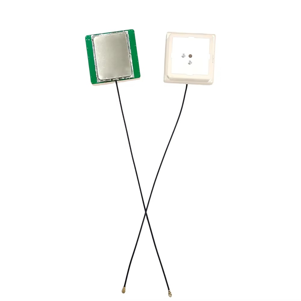
The design and construction of a GPS RTK antenna with tilt compensation are complex processes that require careful integration of multiple components—including the antenna element, tilt sensors, signal processing circuitry, and mechanical housing—to ensure optimal performance, durability, and accuracy. Each component is designed to address specific challenges, from maximizing satellite signal reception to accurately measuring tilt and applying real-time corrections. This section will break down the key design elements and construction considerations of these antennas, highlighting how each part contributes to the overall functionality of the system.
2.1 Antenna Element Design
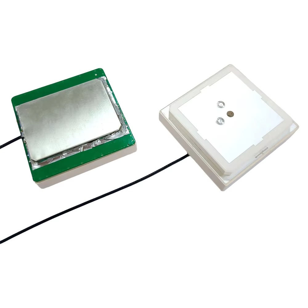
At the core of any GPS RTK antenna is the antenna element, which is responsible for receiving electromagnetic signals from GPS (and other satellite constellations) and converting them into electrical signals for processing. The design of the antenna element is critical to ensuring high signal sensitivity, low noise, and a stable phase center—all of which are essential for RTK accuracy.
Traditional GPS RTK antennas typically use a microstrip patch antenna design, which is well-suited for this application due to its compact size, low profile, and relatively simple construction. A microstrip patch antenna consists of a thin metallic patch (usually copper) printed on a dielectric substrate (e.g., FR4, a common fiberglass-reinforced epoxy material) with a ground plane on the opposite side of the substrate. The patch is fed by a coaxial cable or microstrip line, which excites the antenna to resonate at the frequency of GPS signals (L1: 1575.42 MHz and L2: 1227.60 MHz for GPS; additional frequencies for other constellations like GLONASS, Galileo, and BeiDou).
For tilt-compensated antennas, the patch antenna design must be optimized to minimize the impact of tilt on the phase center. The phase center is the point in the antenna where the signal appears to originate, and any shift in this point due to tilt can introduce positioning errors. To address this, manufacturers use phase center stabilization techniques, such as designing the patch with a symmetric shape (e.g., square, circular) and carefully selecting the substrate material and thickness to ensure that the phase center remains as stable as possible across different tilt angles. Some advanced designs also use multiple patch elements arranged in an array to improve signal reception and phase center stability, particularly in environments with weak or blocked signals (e.g., urban canyons, dense forests).
Another key consideration in antenna element design is polarization. GPS satellite signals are right-hand circularly polarized (RHCP), so the antenna must be designed to receive RHCP signals efficiently. A microstrip patch antenna can be configured for RHCP by introducing a slight asymmetry in the patch (e.g., a truncated corner or a slot) or by using a dual-feed system that excites two orthogonal modes with a 90-degree phase shift. This ensures that the antenna can capture GPS signals regardless of the satellite’s position in the sky.
2.2 Tilt Sensor Integration
The most distinguishing feature of a GPS RTK antenna with tilt compensation is the integration of tilt sensors, which measure the antenna’s orientation relative to the horizontal plane. The choice of tilt sensor technology depends on factors such as accuracy, response time, power consumption, and cost. The three most common types of sensors used are accelerometers, gyroscopes, and inclinometers.
Accelerometers: These sensors measure linear acceleration, including the acceleration due to gravity. By detecting the direction of gravitational acceleration, an accelerometer can determine the antenna’s pitch and roll angles relative to the horizontal. Accelerometers are widely used in tilt-compensated antennas due to their low cost, small size, and low power consumption. However, they are sensitive to dynamic acceleration (e.g., vibration from construction equipment), which can introduce noise into the tilt measurements. To mitigate this, manufacturers often use MEMS (Micro-Electro-Mechanical Systems) accelerometers with high resolution (e.g., 0.1 degrees or better) and integrate filtering algorithms (e.g., Kalman filtering) to separate gravitational acceleration from dynamic acceleration.
Gyroscopes: Gyroscopes measure angular velocity, which can be used to track changes in the antenna’s orientation over time. Unlike accelerometers, gyroscopes are not affected by dynamic acceleration, making them ideal for applications where the antenna is subject to high vibration or rapid movement (e.g., mobile mapping vehicles). However, gyroscopes suffer from drift—a gradual accumulation of error over time—so they are often used in combination with accelerometers in a sensor fusion system. Sensor fusion combines data from multiple sensors to leverage their strengths (accelerometers for long-term stability, gyroscopes for short-term accuracy) and minimize their weaknesses, resulting in more reliable tilt measurements.
Inclinometers: Inclinometers are specialized sensors designed specifically for measuring tilt angles. They can be based on various technologies, including liquid-level (using a bubble in a liquid-filled tube), pendulum (using a weighted pendulum to detect vertical), or MEMS-based designs. Inclinometers offer high accuracy (often <0.01 degrees) and stability, but they are typically larger and more expensive than accelerometers or gyroscopes. They are commonly used in high-precision applications, such as surveying, where even small tilt errors are unacceptable.
The tilt sensors are mounted directly on the antenna’s circuit board or within the mechanical housing, as close to the antenna element as possible to ensure that the measured tilt accurately reflects the orientation of the phase center. The sensors are calibrated during manufacturing to account for any offset or sensitivity errors, and some antennas include user-calibration features to allow for field adjustments if needed.
2.3 Signal Processing Circuitry
Once the antenna element receives the satellite signals and the tilt sensors collect orientation data, the signal processing circuitry is responsible for converting these raw data into usable position information with tilt compensation. This circuitry typically includes a low-noise amplifier (LNA), a downconverter, an analog-to-digital converter (ADC), and a microcontroller or digital signal processor (DSP).
Low-Noise Amplifier (LNA): The LNA is the first component in the signal chain, and its role is to amplify the weak satellite signals (which are often on the order of microvolts) while introducing minimal noise. A high-performance LNA is critical for maintaining signal integrity, especially in environments with high levels of electromagnetic interference (EMI) or weak signal reception. LNAs used in GPS RTK antennas typically have a noise figure (NF) of <1 dB and a gain of 20–30 dB.
Downconverter: The downconverter converts the high-frequency GPS signals (L1 and L2 bands) to a lower intermediate frequency (IF), which is easier to process digitally. This is done using a local oscillator (LO) to mix with the incoming signal, producing an IF signal that retains the original signal’s phase and amplitude information. The downconverter must be highly stable to avoid introducing phase errors, which can degrade RTK accuracy.
Analog-to-Digital Converter (ADC): The ADC converts the analog IF signal into a digital signal that can be processed by the microcontroller or DSP. The ADC’s resolution (number of bits) and sampling rate are key parameters: a higher resolution (e.g., 12–16 bits) allows for more accurate representation of the signal, while a higher sampling rate (e.g., 1–10 MHz) ensures that the signal’s phase information is captured correctly.
Microcontroller/DSP: The microcontroller or DSP is the "brain" of the tilt-compensated antenna. It performs two main tasks: processing the satellite signal data to calculate the initial position (using RTK algorithms) and processing the tilt sensor data to apply compensation corrections. The RTK processing involves comparing the carrier-phase measurements from the rover antenna with the correction data from the base station, while the tilt compensation involves using the pitch and roll angles to adjust the position calculations for phase center shift.
Advanced antennas may also include a field-programmable gate array (FPGA) to accelerate the signal processing, particularly for multi-constellation systems that need to process signals from GPS, GLONASS, Galileo, and BeiDou simultaneously. The FPGA can handle parallel processing tasks, such as correlating satellite signals and filtering noise, much faster than a microcontroller or DSP, improving the antenna’s response time and accuracy.
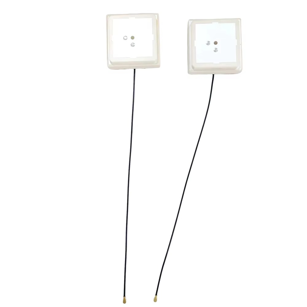
2.4 Mechanical Housing and Environmental Protection
The mechanical housing of a GPS RTK antenna with tilt compensation is designed to protect the internal components (antenna element, sensors, circuitry) from environmental hazards while maintaining optimal signal reception. The housing must be durable enough to withstand the harsh conditions of the applications in which the antenna is used—such as construction sites (dust, vibration, impact), agricultural fields (moisture, chemicals), and outdoor surveying (extreme temperatures, rain, snow).
Most tilt-compensated RTK antennas use a weatherproof housing made from materials like aluminum, plastic (e.g., ABS, polycarbonate), or fiberglass. Aluminum is preferred for its strength and thermal conductivity (which helps dissipate heat from the circuitry), while plastic and fiberglass are lighter and more resistant to corrosion. The housing is typically sealed to meet IP (Ingress Protection) standards, such as IP67 (dust-tight and waterproof up to 1 meter) or IP68 (dust-tight and waterproof up to 1.5 meters), ensuring that no dust or liquid can enter the interior.
The shape of the housing is also important for signal reception. The top of the housing (where the antenna element is located) is usually a smooth, non-metallic dome or flat surface made from a low-loss dielectric material (e.g., Teflon, polypropylene) that allows GPS signals to pass through with minimal attenuation. The sides and bottom of the housing are often made from metal to provide EMI shielding, which protects the internal circuitry from interference from nearby electronic devices (e.g., radios, power tools).
Another key mechanical consideration is the mounting system. The antenna must be securely mounted to the rover or base station equipment (e.g., a survey pole, construction machine, or vehicle roof) while allowing for easy adjustment if needed. Mounting options include threaded studs, magnetic bases, or clamp-on brackets. Some antennas also include a built-in leveling bubble or laser level to assist with initial manual leveling, even though tilt compensation will correct for any remaining tilt.
In summary, the design and construction of a GPS RTK antenna with tilt compensation require a holistic approach that integrates high-performance antenna elements, accurate tilt sensors, advanced signal processing circuitry, and durable mechanical housing. Each component is carefully selected and optimized to work together seamlessly, ensuring that the antenna can provide centimeter-level accuracy even in challenging environments. The next section will explore the working principles of these antennas, explaining how the various components collaborate to deliver tilt-compensated positioning data.
To understand how a GPS RTK antenna with tilt compensation operates, it is essential to break down its working principles into two interconnected processes: the standard RTK positioning workflow and the tilt compensation mechanism. These two processes work in tandem to ensure that the antenna delivers accurate, real-time position data—even when the antenna is tilted. This section will explain each process in detail, highlighting how satellite signal reception, RTK correction, tilt measurement, and compensation algorithms come together to produce reliable positioning results.
3.1 Standard RTK Positioning: The Foundation
Before delving into tilt compensation, it is critical to first grasp the working principles of standard GPS RTK technology, as tilt compensation builds upon this foundation. RTK positioning relies on the precise measurement of the carrier phase of GPS satellite signals, which is far more accurate than the code-phase measurements used in basic GPS (which typically provide 1–10 meter accuracy).
The GPS system consists of a constellation of 24–32 satellites orbiting Earth at an altitude of approximately 20,200 km. Each satellite transmits two main signals: the C/A (Coarse/Acquisition) code (on the L1 frequency) and the P (Precise) code (on both L1 and L2 frequencies). These codes are pseudorandom sequences that allow the receiver to determine the time it takes for the signal to travel from the satellite to the receiver (time of flight, TOF). By multiplying the TOF by the speed of light, the receiver calculates the distance (pseudorange) between the satellite and the receiver.
To determine its position, a GPS receiver needs pseudoranges from at least four satellites (to solve for three spatial coordinates—latitude, longitude, altitude—and the receiver’s clock error). However, basic GPS positioning is affected by several sources of error, including:Ionospheric Delay: The ionosphere (a layer of Earth’s atmosphere 50–1,000 km above the surface) contains charged particles that slow down GPS signals, causing delays that vary with solar activity and signal frequency.
Tropospheric Delay: The troposphere (the lowest layer of the atmosphere, up to 12 km) causes signal delays due to water vapor, temperature, and pressure variations. Unlike ionospheric delay, tropospheric delay affects both L1 and L2 frequencies equally.
Satellite Clock Error: Small inaccuracies in the satellite’s atomic clock can lead to errors in TOF measurements, as the clock is used to timestamp the transmitted signal.
Satellite Orbit Error (Ephemeris Error): Errors in the satellite’s reported orbit (ephemeris data) can cause the receiver to miscalculate the satellite’s position, leading to pseudorange errors.
Multipath Interference: GPS signals can reflect off nearby objects (e.g., buildings, trees, water) before reaching the receiver, creating multiple signal paths. The receiver may mistakenly use the reflected signal instead of the direct one, leading to position errors.
RTK technology mitigates these errors by using a base station and rover system, as mentioned in the Overview. Here’s a step-by-step breakdown of the standard RTK workflow:
Base Station Setup: The base station is installed at a location with a known, surveyed position (e.g., a permanent survey marker). This known position is critical, as it serves as a reference point for calculating errors.
Base Station Signal Measurement: The base station’s GPS antenna continuously receives signals from visible satellites and measures the carrier phase of each signal. It then calculates the theoretical pseudorange between itself and each satellite using its known position and the satellite’s orbit data (from the satellite’s navigation message).
Error Calculation: The base station compares the measured pseudorange (from the carrier phase) with the theoretical pseudorange. The difference between these two values represents the error correction for that satellite—this correction accounts for ionospheric delay, tropospheric delay, satellite clock error, and orbit error.
Correction Data Transmission: The base station packages the error corrections (along with information about the satellites it is tracking) into a data stream and transmits it to the rover via a communication link. Common communication methods include UHF radio (for short-range applications, up to 10 km), cellular networks (GSM, LTE, 5G for longer ranges), or satellite communication (for remote areas with no cellular coverage).
Rover Signal Measurement and Correction: The rover’s GPS antenna (which is the focus of this analysis) receives signals from the same satellites as the base station and measures their carrier phases. It also receives the correction data from the base station and applies the corrections to its own pseudorange measurements.
Position Calculation: Using the corrected pseudoranges, the rover’s receiver calculates its precise position in real time. Because the base station and rover are relatively close (typically within 10–20 km for optimal accuracy), the errors affecting both units are highly correlated—this means the corrections from the base station effectively cancel out the errors in the rover’s measurements, resulting in centimeter-level accuracy.
A key technical detail in RTK positioning is the ambiguity resolution process. The carrier phase measurement is a fractional value of the signal’s wavelength (e.g., ~19 cm for L1, ~24 cm for L2), so the receiver must determine the integer number of full wavelengths between the satellite and the receiver (the “ambiguity”). Resolving these ambiguities correctly is essential for achieving centimeter-level accuracy. Modern RTK receivers use advanced algorithms (e.g., Least Squares Ambiguity Decorrelation Adjustment, LAMBDA) to quickly and reliably resolve ambiguities, even in challenging signal environments.
3.2 Tilt Compensation Mechanism: Enhancing RTK Accuracy
While standard RTK provides high accuracy when the antenna is perfectly horizontal, tilt introduces additional errors that must be corrected. The tilt compensation mechanism addresses these errors by integrating tilt sensor data into the RTK position calculation process. This mechanism can be broken down into three key steps: tilt measurement, error modeling, and correction application.
3.2.1 Tilt Measurement: Capturing Antenna Orientation
As discussed in the Design and Construction section, the tilt-compensated antenna integrates sensors (accelerometers, gyroscopes, or inclinometers) to measure the antenna’s pitch and roll angles. These sensors operate continuously, sampling orientation data at a high rate (typically 10–100 Hz) to keep up with dynamic changes in the antenna’s position (e.g., a rover moving over rough terrain).
Pitch and Roll Calculation: For accelerometers, the sensor measures the component of gravitational acceleration along its x, y, and z axes. When the antenna is horizontal, the z-axis (vertical) aligns with gravity, so the z-axis acceleration is ~9.81 m/s², and the x and y axes (horizontal) measure 0 m/s². When the antenna tilts, the gravitational acceleration is distributed across the x, y, and z axes. The pitch angle (θ) and roll angle (φ) can be calculated using trigonometric relationships:
Pitch (θ) = arctan2(ax, √(ay² + az²))
Roll (φ) = arctan2(ay, az)
Where ax, ay, and az are the accelerations along the x, y, and z axes, respectively.
Sensor Fusion for Dynamic Environments: In applications where the antenna is subject to vibration or rapid movement (e.g., a construction vehicle), accelerometers alone may produce noisy tilt measurements due to dynamic acceleration. To address this, the antenna uses sensor fusion—combining data from accelerometers and gyroscopes. The gyroscope measures angular velocity (rate of change of pitch and roll), which is integrated over time to calculate orientation changes. The accelerometer provides long-term stability (since it references gravity), while the gyroscope provides short-term accuracy (since it is unaffected by vibration). A Kalman filter is often used to combine these data streams: it uses a mathematical model to predict the antenna’s orientation based on gyroscope data, then updates the prediction using accelerometer data to correct for drift and noise.
The tilt sensor data is time-stamped to ensure it is synchronized with the satellite signal measurements. This synchronization is critical, as the antenna’s orientation at the time of signal reception directly affects the phase center position and signal distortion.
3.2.2 Error Modeling: Quantifying Tilt-Induced Errors
Once the pitch and roll angles are measured, the next step is to model the errors caused by tilt. The primary sources of tilt-induced error are phase center shift and signal reception pattern distortion.
Phase Center Shift: The phase center of the antenna is the point from which the satellite signal appears to be received. For a perfectly horizontal antenna, the phase center is at a known location relative to the antenna’s physical mount (e.g., the bottom of the housing). When the antenna tilts, the phase center shifts horizontally relative to the mount. The magnitude of this shift depends on the tilt angle and the height of the phase center above the mount (the “phase center height”). For example, if the phase center is 10 cm above the mount and the antenna tilts by 10 degrees, the horizontal shift is approximately 10 cm × sin(10°) ≈ 1.7 cm—this shift would directly translate to a position error if uncorrected.
To model this shift, the antenna’s software uses the measured pitch and roll angles and the known phase center height to calculate the horizontal displacement (Δx, Δy) of the phase center relative to the mount. This displacement is then used to adjust the rover’s position calculation.
Signal Reception Pattern Distortion: The antenna’s radiation pattern (the directionality of signal reception) is optimized for horizontal operation. When the antenna tilts, the radiation pattern tilts with it, reducing the antenna’s sensitivity to signals from satellites in certain directions. For example, a tilted antenna may have reduced sensitivity to satellites near the horizon, leading to fewer tracked satellites or weaker signal strength. This can degrade the accuracy of the RTK position calculation, as fewer satellites mean fewer pseudoranges to use in solving for position.
To mitigate this, some advanced tilt-compensated antennas use adaptive beamforming—a technique that adjusts the radiation pattern of the antenna array to maintain sensitivity to key satellites, even when tilted. Beamforming uses multiple patch elements and phase shifters to focus the antenna’s reception in the direction of the satellites, compensating for the tilt-induced distortion.
3.2.3 Correction Application: Integrating Tilt Data into RTK Positioning
The final step in the tilt compensation mechanism is applying the calculated corrections to the RTK position data. This integration happens in the rover’s receiver (or the antenna’s embedded processing unit) and involves adjusting both the pseudorange measurements and the final position calculation.
Pseudorange Adjustment: The tilt-induced phase center shift causes the measured pseudoranges to be offset by the horizontal displacement of the phase center. To correct this, the receiver adjusts each pseudorange by the component of the phase center shift in the direction of the satellite. For example, if the phase center shifts 1 cm to the east and a satellite is located to the east of the rover, the pseudorange to that satellite is reduced by 1 cm (since the phase center is now closer to the satellite). This adjustment ensures that the pseudoranges accurately represent the distance from the satellite to the antenna’s actual phase center.
Position Calculation Adjustment: After adjusting the pseudoranges, the receiver calculates the initial RTK position using the standard RTK algorithm. It then applies a further correction to account for the phase center shift relative to the rover’s physical location (e.g., the mount point on a survey pole or construction machine). This correction involves subtracting the horizontal displacement (Δx, Δy) of the phase center from the initial position, resulting in the final, tilt-compensated position.
Real-Time Updates: The entire tilt compensation process—from tilt measurement to correction application—occurs in real time, typically at the same rate as the RTK position update (1–10 Hz). This ensures that the position data remains accurate even as the antenna’s orientation changes dynamically. For example, if a surveyor is walking with a rover pole on a sloped path, the antenna tilts continuously, but the tilt compensation system adjusts the position data instantaneously, maintaining centimeter-level accuracy.
It is important to note that tilt compensation has limitations. Most antennas have a maximum tilt range (typically ±15 to ±30 degrees) beyond which the phase center shift becomes too large to correct accurately, and the radiation pattern distortion becomes severe. Additionally, yaw (rotation around the vertical axis) is not typically compensated for by basic tilt sensors, as it does not affect the horizontal position of the phase center—however, some advanced systems integrate magnetometers to measure yaw and correct for any orientation-dependent errors (e.g., in applications where the rover’s direction of movement is critical).
3.3 Synergy Between RTK and Tilt Compensation
The working principles of GPS RTK antennas with tilt compensation highlight the synergy between the standard RTK workflow and the tilt compensation mechanism. RTK provides the foundation of centimeter-level accuracy by correcting for satellite and atmospheric errors, while tilt compensation addresses the real-world challenge of antenna tilt, ensuring that this accuracy is maintained in dynamic, uneven environments. Without RTK, tilt compensation would be irrelevant—basic GPS cannot provide the precision needed for tilt-induced errors to matter. Without tilt compensation, RTK accuracy would be limited to applications where the antenna can be perfectly leveled, which is often impractical in the field.
This synergy is particularly evident in the timing of the two processes. The RTK system requires continuous, accurate pseudorange measurements to calculate position, while the tilt compensation system requires continuous, synchronized tilt measurements to correct those pseudoranges. The integration of these two data streams—satellite signals and tilt sensor data—into a single, real-time processing workflow is what makes tilt-compensated GPS RTK antennas so powerful.
In summary, the working principles of a GPS RTK antenna with tilt compensation involve two core processes: standard RTK positioning, which uses carrier-phase measurements and base station corrections to achieve centimeter-level accuracy, and tilt compensation, which uses sensor data to measure antenna orientation, model tilt-induced errors, and apply corrections to the position data. By combining these processes, the antenna delivers reliable, high-accuracy positioning even in the challenging, dynamic environments where it is most needed. The next section will explore the advantages and challenges of this technology, providing a balanced view of its performance and limitations.
GPS RTK antennas with tilt compensation offer a range of advantages that have made them indispensable in precision positioning applications, but they also face significant challenges that can limit their performance in certain scenarios. Understanding these advantages and challenges is critical for users—such as surveyors, construction managers, and agricultural engineers—to make informed decisions about whether to adopt this technology and how to optimize its use. This section will explore the key benefits of tilt-compensated RTK antennas, as well as the technical, environmental, and practical challenges they encounter.
4.1 Key Advantages of GPS RTK Antennas with Tilt Compensation
The primary advantage of tilt-compensated RTK antennas is their ability to maintain high accuracy in real-world, dynamic environments—but this technology offers several other benefits that enhance efficiency, reliability, and usability across industries.
4.1.1 Enhanced Accuracy in Uneven Terrain
The most significant advantage of tilt compensation is its ability to correct for position errors caused by antenna tilt, ensuring that centimeter-level RTK accuracy is maintained even when the antenna is not perfectly horizontal. In applications where terrain is uneven—such as construction sites with slopes, agricultural fields with rolling hills, or surveying projects in mountainous areas—traditional RTK antennas would require time-consuming manual leveling to avoid errors. Tilt-compensated antennas eliminate this need: the sensors automatically measure tilt, and the software applies corrections, allowing users to work faster without sacrificing accuracy.
For example, in road construction, a grader equipped with a tilt-compensated RTK antenna can operate on sloped terrain while maintaining the exact grade specified in the design plans. Without tilt compensation, the grader operator would need to stop frequently to level the antenna, slowing down the construction process and increasing the risk of errors. With tilt compensation, the antenna adjusts for tilt in real time, ensuring that the grader’s blade stays at the correct height and angle, resulting in a smoother, more accurate road surface.
4.1.2 Increased Operational Efficiency
By eliminating the need for manual leveling, tilt-compensated RTK antennas significantly reduce the time and effort required to set up and operate RTK systems. In surveying, for instance, traditional RTK surveys require surveyors to use a bubble level or laser level to ensure the antenna is horizontal before taking measurements—a process that can take several minutes per measurement point. With a tilt-compensated antenna, surveyors can set up the rover pole quickly, even on sloped ground, and start taking measurements immediately. This increase in efficiency can reduce project timelines by 20–30%, according to industry studies, allowing surveyors to complete more work in less time.
Efficiency is also improved in dynamic applications, such as mobile mapping or precision agriculture. In mobile mapping, a vehicle equipped with a tilt-compensated RTK antenna can drive over rough roads or uneven terrain while capturing accurate geospatial data (e.g., for road maintenance or urban planning). Without tilt compensation, the antenna’s tilt would cause errors in the mapping data, requiring post-processing to correct—or, in the worst case, rendering the data unusable. With tilt compensation, the data is accurate in real time, eliminating the need for post-processing and speeding up the mapping workflow.
4.1.3 Improved Reliability in Dynamic Environments
Tilt-compensated RTK antennas are designed to handle the dynamic conditions of real-world applications, such as vibration, movement, and changing terrain. The integration of sensor fusion (accelerometers + gyroscopes) ensures that tilt measurements remain accurate even when the antenna is subject to vibration—for example, on a construction excavator or a agricultural tractor. This reliability is critical in applications where downtime or errors can be costly: a single error in a construction project can lead to rework, which costs time and money, while an error in precision agriculture can result in over- or under-application of inputs, reducing crop yields.
Additionally, the ability to maintain accuracy with fewer manual interventions reduces the risk of human error. Manual leveling requires skill and attention to detail—even a small mistake (e.g., misreading the bubble level) can lead to significant position errors. Tilt-compensated antennas automate the leveling process, removing the human element and ensuring consistent, reliable results.
4.1.4 Compatibility with Multi-Constellation Systems
Many modern tilt-compensated RTK antennas are designed to work with multiple satellite constellations, including GPS, GLONASS (Russia), Galileo (EU), and BeiDou (China). This multi-constellation compatibility improves signal availability and redundancy, which is particularly beneficial in challenging signal environments—such as urban canyons (where buildings block signals) or dense forests (where trees attenuate signals). By tracking more satellites, the antenna can maintain RTK lock (the ability to receive and process correction data) even when some satellites are blocked, ensuring continuous accuracy.
Tilt compensation enhances this benefit by ensuring that even if the antenna tilts to capture signals from overhead satellites (to avoid blocked horizon satellites), the position data remains accurate. For example, in an urban environment, a tilt-compensated antenna mounted on a survey pole can be tilted upward to track satellites above the buildings, and the tilt compensation system will correct for the tilt, maintaining centimeter-level accuracy. Without tilt compensation, tilting the antenna to capture overhead signals would introduce errors, making it impossible to work in such environments.
4.1.5 Reduced Equipment Costs (Long-Term)
While tilt-compensated RTK antennas may have a higher upfront cost than traditional RTK antennas, they can reduce long-term equipment costs by eliminating the need for additional leveling tools. Traditional RTK systems require separate bubble levels, laser levels, or leveling bases to ensure the antenna is horizontal—these tools add tothe overall equipment cost and require regular maintenance (e.g., calibrating laser levels). Tilt-compensated antennas integrate leveling functionality into the device itself, eliminating the need for these extra tools. Additionally, the increased efficiency and reduced rework associated with tilt compensation can lower labor costs over time. For example, a construction company using tilt-compensated antennas may require fewer workers to complete a grading project, as the equipment operates more efficiently and with fewer errors. Over the lifespan of a project or a fleet of equipment, these cost savings can far outweigh the initial premium for tilt-compensated technology.
4.2 Key Challenges of GPS RTK Antennas with Tilt Compensation
Despite their numerous advantages, GPS RTK antennas with tilt compensation face several challenges that can impact their performance, usability, and cost-effectiveness. These challenges range from technical limitations of tilt sensors to environmental factors that disrupt signal reception, and they require careful consideration when deploying the technology.
4.2.1 Technical Limitations of Tilt Sensors
The accuracy of tilt compensation is heavily dependent on the performance of the integrated tilt sensors (accelerometers, gyroscopes, inclinometers). While sensor fusion techniques improve reliability, these sensors still have inherent limitations that can introduce errors:
Accelerometer Sensitivity to Dynamic Acceleration: Even with filtering, accelerometers are susceptible to noise from dynamic acceleration—such as the vibration of a moving vehicle or the jostling of a survey pole. This noise can cause incorrect tilt measurements, leading to inaccurate compensation. For example, if a surveyor is walking quickly with a rover pole, the accelerometer may mistake the forward acceleration of the pole for tilt, resulting in a position error of 1–2 cm. While Kalman filters reduce this noise, they cannot eliminate it entirely, especially in high-vibration environments.
Gyroscope Drift: Gyroscopes suffer from drift, where the measured angular velocity gradually deviates from the true value over time. This drift can accumulate, leading to significant tilt measurement errors after extended use (e.g., 0.1 degrees of drift per hour). Sensor fusion with accelerometers helps correct for drift, but if the accelerometer data is noisy (e.g., in dynamic environments), the drift correction becomes less effective. This is a particular challenge in applications that require continuous operation for hours at a time, such as long-distance surveying or 24-hour construction projects.
Calibration Requirements: Tilt sensors require regular calibration to maintain accuracy. Over time, factors like temperature changes, physical shock (e.g., dropping the antenna), or component aging can cause sensor offsets or sensitivity changes. Calibration typically involves placing the antenna in a known horizontal position and adjusting the sensor data to match the true orientation. While some antennas offer automated calibration, many require manual calibration using specialized equipment (e.g., a precision tilt table), which adds time and complexity to the maintenance process. If calibration is neglected, tilt measurements can become inaccurate, leading to failed compensation and position errors.
4.2.2 Environmental Factors Disrupting Performance
GPS RTK antennas—including tilt-compensated models—rely on strong, unobstructed satellite signals to function. Environmental factors that block or distort these signals can degrade RTK performance, and tilt compensation cannot overcome these challenges:
Signal Obstruction (Urban Canyons, Forests): In urban environments, tall buildings create “urban canyons” that block signals from low-elevation satellites. In dense forests, tree canopies attenuate signals, reducing their strength. While tilt compensation allows the antenna to tilt toward overhead satellites (which are less likely to be blocked), if there are too few overhead satellites (e.g., only 2–3 visible), the RTK system cannot resolve ambiguities or calculate a position accurately. This leads to “RTK dropouts,” where the system loses centimeter-level accuracy and reverts to lower-precision modes (e.g., DGPS). Tilt compensation cannot fix this issue, as it only corrects for tilt—not a lack of satellite signals.
Electromagnetic Interference (EMI): EMI from nearby electronic devices—such as radios, power lines, or construction equipment (e.g., welders, cranes)—can disrupt the satellite signals received by the antenna. EMI can cause signal noise, leading to inaccurate carrier-phase measurements and, consequently, position errors. While the antenna’s metal housing provides some EMI shielding, strong interference (e.g., from a high-power radio transmitter) can still penetrate the housing. Tilt compensation does not address EMI-related errors, as it only corrects for tilt-induced issues. This is a major challenge in industrial environments, where EMI sources are abundant.
Extreme Weather Conditions: Extreme temperatures, humidity, rain, snow, or ice can impact both the antenna’s electronics and the satellite signals. For example, high temperatures can cause the antenna’s circuit board to overheat, leading to sensor drift or signal processing errors. Heavy rain or snow can attenuate satellite signals, reducing their strength and increasing noise. While tilt-compensated antennas are designed to be weatherproof (e.g., IP67 or IP68 ratings), extreme conditions can still degrade performance. For instance, ice buildup on the antenna’s dome can block signals, even if the tilt sensors are still functioning correctly. Tilt compensation cannot correct for signal loss due to ice or extreme weather, making it challenging to use the technology in harsh climates.
4.2.3 Cost Barriers and Complexity
Tilt-compensated RTK antennas are more complex and expensive than traditional RTK antennas, which can be a barrier to adoption—especially for small businesses or individual users:
Higher Upfront Costs: The integration of tilt sensors, sensor fusion circuitry, and advanced software increases the manufacturing cost of tilt-compensated antennas. A high-quality tilt-compensated RTK antenna can cost 30–50% more than a comparable traditional RTK antenna (e.g., \(1,500–\)3,000 for a tilt-compensated model vs. \(1,000–\)2,000 for a traditional model). For users with limited budgets—such as small surveying firms or independent farmers—this price difference can be prohibitive, even if the long-term cost savings are significant.
Increased Complexity for Users: Tilt-compensated antennas require users to understand and configure additional settings related to tilt compensation—such as setting the maximum tilt range, calibrating the sensors, or adjusting the sensor fusion parameters. This adds complexity to the setup and operation of the system. For users with limited technical expertise (e.g., farmers new to precision agriculture), this complexity can lead to incorrect configuration, resulting in inaccurate compensation or system failure. While manufacturers provide user manuals and training, the learning curve is steeper than with traditional RTK antennas.
Maintenance Costs: The additional components (tilt sensors, sensor fusion circuitry) in tilt-compensated antennas increase maintenance costs. If a tilt sensor fails, it must be replaced—often by a qualified technician, as the sensor is integrated into the antenna’s circuit board. This is more expensive than maintaining a traditional antenna, which has fewer moving or sensitive components. Additionally, regular calibration of the tilt sensors adds to the maintenance workload and cost, especially for large fleets of antennas (e.g., a construction company with 10+ rovers).
4.2.4 Limitations in High-Speed or High-Tilt Applications
Tilt-compensated RTK antennas have performance limitations in applications where the antenna is moving at high speeds or tilting beyond the maximum compensation range:
High-Speed Applications: In applications where the rover is moving at high speeds (e.g., mobile mapping vehicles traveling at 60+ km/h), the tilt sensors may not be able to sample orientation data quickly enough to keep up with rapid changes in tilt. For example, if the vehicle hits a pothole, the antenna tilts suddenly, but the sensor sampling rate (10–100 Hz) may not capture the full extent of the tilt before the vehicle stabilizes. This leads to incomplete compensation, resulting in a temporary position error. While some advanced antennas offer higher sampling rates (200+ Hz), they are more expensive and consume more power.
Exceeding Maximum Tilt Range: Most tilt-compensated antennas have a maximum tilt range of ±15 to ±30 degrees. If the antenna tilts beyond this range (e.g., a survey pole falling over, or a construction machine operating on a steep slope of 40 degrees), the tilt compensation system cannot correct for the error. The phase center shift becomes too large to model accurately, and the radiation pattern distortion is severe, leading to significant position errors (10+ cm). In such cases, the system may alert the user to the excessive tilt, but it cannot provide accurate data until the antenna is repositioned within the compensation range. This is a major limitation in applications where steep terrain is common, such as mountain surveying or mining.
4.3 Balancing Advantages and Challenges
To maximize the value of GPS RTK antennas with tilt compensation, users must balance their advantages against their challenges. This involves:
Selecting the Right Antenna for the Application: Choosing an antenna with the appropriate tilt sensor technology (e.g., accelerometer-gyroscope fusion for dynamic environments, inclinometers for high-precision static surveying) and maximum tilt range (e.g., ±30 degrees for steep terrain) to match the application’s needs.
Investing in Calibration and Maintenance: Regularly calibrating tilt sensors and maintaining the antenna to ensure accurate performance. This may involve scheduling monthly calibration checks or training staff to perform basic maintenance tasks.
Mitigating Environmental Challenges: Using multi-constellation antennas to improve signal availability in urban or forested areas, and installing EMI shielding (e.g., additional metal enclosures) in industrial environments to reduce interference.
Training Users: Providing comprehensive training to users on how to configure, operate, and troubleshoot tilt-compensated antennas, reducing the risk of errors due to complexity.
By addressing these challenges, users can leverage the full potential of tilt-compensated RTK antennas, enjoying the benefits of enhanced accuracy, efficiency, and reliability while minimizing the impact of limitations.
5.1 Key Applications of GPS RTK Antennas with Tilt Compensation
The versatility of tilt-compensated RTK antennas makes them suitable for a wide range of applications, each leveraging the technology’s unique strengths—such as real-time accuracy, tilt correction, and multi-constellation compatibility.
5.1.1 Construction and Machine Control
The construction industry is one of the largest users of tilt-compensated GPS RTK antennas, primarily for machine control—a technology that uses precision positioning to guide construction equipment (e.g., excavators, bulldozers, graders, pavers) with minimal human intervention. Tilt compensation is critical in this application, as construction equipment often operates on sloped terrain, and even small antenna tilt can lead to costly errors in earthmoving, grading, or paving.
Grading and Earthmoving: Graders equipped with tilt-compensated RTK antennas use the technology to maintain a precise grade (slope) as specified in the project’s design plans. The antenna is mounted on the grader’s blade or cab, and tilt compensation corrects for the equipment’s tilt as it moves over uneven ground. For example, when grading a road base, the antenna ensures that the blade stays at the exact elevation and slope needed, even if the grader is on a side slope of 10–15 degrees. This eliminates the need for manual staking (placing wooden stakes to mark grade) and reduces rework, as the grade is accurate on the first pass.
Excavation: Excavators use tilt-compensated RTK antennas to dig trenches, foundations, or basins to precise depths and dimensions. The antenna is mounted on the excavator’s bucket or arm, and tilt compensation corrects for the arm’s tilt as it moves. For instance, when digging a foundation for a building, the antenna ensures that the trench is exactly 1.5 meters deep and 0.8 meters wide, even if the excavator is on uneven ground. This improves safety (as workers do not need to stand near the bucket to guide the operator) and increases efficiency, as the excavator can work faster without manual checks.
Paving: Pavers use tilt-compensated RTK antennas to lay asphalt or concrete to a precise thickness and slope. The antenna is mounted on the paver’s screed (the component that levels the asphalt), and tilt compensation corrects for the screed’s tilt as the paver moves. This ensures that the road surface is smooth and even, with no high or low spots, which is critical for road durability and safety. Tilt-compensated RTK also allows pavers to work in curved sections of the road, as the antenna adjusts for the paver’s lateral tilt.
Major construction equipment manufacturers—such as Caterpillar, John Deere, and Volvo Construction Equipment—integrate tilt-compensated RTK antennas into their machine control systems, offering turnkey solutions for contractors.
5.1.2 Precision Agriculture
Precision agriculture (PA) uses technology to optimize crop yields, reduce input costs (e.g., fertilizers, pesticides, water), and minimize environmental impact. Tilt-compensated GPS RTK antennas are a cornerstone of PA, as they enable accurate positioning of agricultural equipment (e.g., tractors, harvesters, sprayers) in fields with rolling hills or uneven terrain.
Variable-Rate Application (VRA): VRA involves applying inputs (fertilizers, pesticides) at variable rates across a field, based on soil conditions, crop health, or yield data. Tilt-compensated RTK antennas ensure that the equipment applies the correct rate of input to each area of the field, even if the tractor is on a slope. For example, a sprayer equipped with the antenna can apply more pesticide to a section of the field with high pest pressure and less to a section with low pressure, all while moving over rolling hills. Tilt compensation corrects for the sprayer’s tilt, ensuring that the application rate is accurate and that chemicals do not drift outside the target area.
Auto-Steering: Auto-steering systems use tilt-compensated RTK antennas to guide tractors along precise paths (e.g., 2–5 cm accuracy) in the field. This eliminates “overlapping” (tilling or spraying the same area twice) and “skipping” (missing areas), which waste inputs and reduce yields. Auto-steering is particularly useful in large fields or during low-visibility conditions (e.g., early morning fog), where manual steering is error-prone. Tilt compensation ensures that the auto-steering system remains accurate even when the tractor is on a slope, as the antenna corrects for tilt-induced position errors.
Harvest Mapping: Harvesters equipped with tilt-compensated RTK antennas collect yield data (e.g., bushels per acre) as they harvest the crop. The antenna records the exact position of each yield measurement, even if the harvester is on uneven ground. This data is used to create yield maps, which farmers analyze to identify areas of the field with high or low yields. The maps help farmers make informed decisions about future crop management (e.g., adjusting fertilizer rates in low-yield areas). Tilt compensation ensures that the yield data is geospatially accurate, making the maps reliable for decision-making.
Agricultural technology companies like Trimble Agriculture, Topcon Precision Agriculture, and Deere & Company offer tilt-compensated RTK solutions tailored to the needs of farmers, including antennas that are resistant to dust, moisture, and chemical exposure.
5.1.3 Surveying and Mapping
Surveying and mapping involve measuring and recording the shape, size, and position of features on Earth’s surface. Tilt-compensated GPS RTK antennas have revolutionized this industry by reducing setup time, improving accuracy in challenging terrain, and enabling dynamic mapping.
Topographic Surveying: Topographic surveys create maps of the Earth’s surface, including elevation data (contours). Surveyors use tilt-compensated RTK antennas mounted on survey poles to collect elevation measurements in hilly or mountainous areas. Without tilt compensation, surveyors would need to level the pole manually at each measurement point—a time-consuming process. With tilt compensation, the surveyor can walk quickly over rough terrain, and the antenna automatically corrects for pole tilt, collecting accurate elevation data in a fraction of the time. This is particularly useful for large-scale surveys (e.g., mapping a national park) or surveys in remote areas with no access to power.
Cadastral Surveying: Cadastral surveys define property boundaries, which are used for land ownership, legal disputes, and urban planning. These surveys require extremely high accuracy (often <1 cm), and tilt compensation is critical to achieving this. Surveyors use tilt-compensated RTK antennas to measure boundary markers, even if the ground is sloped. The antenna’s tilt correction ensures that the boundary measurements are legally defensible, as any error could lead to costly legal disputes. Additionally, tilt compensation reduces the time required to set up the survey, as the pole does not need to be perfectly leveled.
Mobile Mapping: Mobile mapping systems (MMS) use vehicles equipped with tilt-compensated RTK antennas, LiDAR (Light Detection and Ranging), and cameras to collect geospatial data (e.g., 3D models of roads, buildings, or infrastructure) as the vehicle moves. The tilt-compensated antenna provides the precise position of the MMS, which is used to georeference the LiDAR and camera data. Tilt compensation is essential in this application, as the vehicle may drive over rough roads or uneven terrain, causing the antenna to tilt. Without tilt compensation, the georeferenced data would be inaccurate, making the 3D models unusable. Mobile mapping is used for applications like road maintenance (identifying potholes), urban planning (modeling cityscapes), and disaster response (mapping damage after an earthquake).
Leading surveying equipment manufacturers, such as Leica Geosystems, Trimble, and Topcon, offer dedicated tilt-compensated RTK antennas for surveying and mapping, with features like lightweight designs (for easy pole mounting) and high-precision sensors (for sub-centimeter accuracy).
5.1.4 Autonomous Vehicles and Robotics
The rise of autonomous vehicles (AVs) and industrial robotics has created a new demand for tilt-compensated GPS RTK antennas, as these systems require precise, real-time positioning to navigate safely and efficiently. Tilt compensation is critical in this application, as AVs and robots often operate on uneven surfaces (e.g., unpaved roads, factory floors) and may experience tilt due to movement or payload changes.
Autonomous Agricultural Robots: Small, autonomous robots used for tasks like weeding, seeding, or crop monitoring rely on tilt-compensated RTK antennas to navigate between crop rows with centimeter-level accuracy. These robots are often lightweight and operate on uneven field terrain, making tilt a common issue. For example, a weeding robot equipped with a tilt-compensated antenna can identify and remove weeds without damaging crops, even if the robot tilts slightly while moving over mounds of soil. Tilt compensation ensures that the robot’s position data remains accurate, allowing it to stay on course and target weeds precisely.
Autonomous Construction Robots: Construction robots—such as brick-laying robots, concrete-finishing robots, or material-handling robots—use tilt-compensated RTK antennas to perform repetitive tasks with high precision. For instance, a brick-laying robot needs to place each brick in an exact position (within 1–2 cm) to ensure the wall is straight and level. If the robot is on a sloped construction site, the antenna’s tilt compensation corrects for the robot’s tilt, ensuring that the bricks are placed accurately. This reduces the need for human oversight and improves the consistency of the construction work.
Autonomous Off-Highway Vehicles: Off-highway AVs—such as mining trucks, forestry vehicles, or agricultural tractors—operate in harsh, uneven environments where traditional positioning systems fail. Tilt-compensated RTK antennas provide these vehicles with the accuracy needed to navigate without human intervention. For example, a mining truck using a tilt-compensated antenna can transport ore from the mine face to the processing plant along a pre-defined route, even on rough, sloped terrain. Tilt compensation corrects for the truck’s tilt as it moves over rocks or uneven ground, ensuring that it stays on the route and avoids collisions with other vehicles or obstacles.
Companies like NVIDIA, Velodyne, and Trimble are developing integrated positioning systems for AVs and robotics that combine tilt-compensated RTK antennas with other sensors (e.g., LiDAR, cameras) to create a “sensor suite” that delivers reliable, redundant positioning.
5.1.5 Disaster Response and Emergency Services
Disaster response teams (e.g., FEMA, Red Cross) and emergency services (e.g., fire departments, search and rescue) use tilt-compensated GPS RTK antennas to map disaster zones, locate survivors, and coordinate relief efforts. These applications require fast, accurate positioning in chaotic, damaged environments where terrain is often uneven or obstructed.
Post-Disaster Mapping: After natural disasters like earthquakes, floods, or hurricanes, tilt-compensated RTK antennas are used to create detailed maps of the damage. Surveyors or drones equipped with the antennas can quickly collect data on collapsed buildings, flooded areas, or blocked roads, even if the terrain is sloped or covered in debris. Tilt compensation ensures that the mapping data is accurate, which helps emergency managers prioritize relief efforts (e.g., directing rescue teams to areas with the most damage).
Search and Rescue (SAR): SAR teams use tilt-compensated RTK antennas to locate missing persons in remote or rough terrain (e.g., mountains, forests). The antennas are mounted on SAR vehicles or carried by team members on survey poles, allowing them to record the exact position of search areas and any evidence found (e.g., footprints, debris). Tilt compensation ensures that the position data is accurate even on steep slopes, reducing the risk of missing the target and speeding up the rescue process.
Infrastructure Inspection: After a disaster, tilt-compensated RTK antennas are used to inspect critical infrastructure like bridges, dams, or power lines for damage. Inspectors mount the antennas on drones or inspection vehicles to collect precise position data of cracks, deformations, or other damage. Tilt compensation corrects for the tilt of the drone or vehicle as it moves around the structure, ensuring that the damage is located accurately. This helps engineers assess the safety of the infrastructure and plan repairs.
5.2 Future Trends in GPS RTK Antennas with Tilt Compensation
As technology advances and user needs evolve, several key trends are emerging that will shape the future of GPS RTK antennas with tilt compensation. These trends focus on improving accuracy, reducing cost, enhancing connectivity, and expanding compatibility—making the technology more accessible and effective for a wider range of applications.
5.2.1 Integration of Artificial Intelligence (AI) and Machine Learning (ML)
The integration of AI and ML into tilt-compensated RTK antennas is expected to revolutionize their performance by enabling adaptive tilt compensation and predictive maintenance.
Adaptive Tilt Compensation: AI algorithms can analyze real-time data from tilt sensors, satellite signals, and environmental sensors (e.g., temperature, vibration) to adjust the compensation parameters dynamically. For example, if the antenna detects high vibration (e.g., on a construction excavator), the AI algorithm can increase the weighting of gyroscope data (which is less sensitive to vibration) in the sensor fusion process, improving the accuracy of tilt measurements. Similarly, if the antenna is in an urban canyon with few satellites, the AI can adjust the beamforming pattern to focus on the available satellites, reducing signal loss. This adaptive approach ensures that the antenna performs optimally in any environment, without requiring manual configuration by the user.
Predictive Maintenance: ML algorithms can analyze historical data from the antenna’s sensors (e.g., sensor drift, signal strength, power consumption) to predict when components are likely to fail. For example, if the algorithm detects that a gyroscope’s drift rate is increasing over time, it can alert the user to calibrate or replace the sensor before it causes a failure. This reduces unplanned downtime and maintenance costs, as users can address issues proactively rather than reacting to failures. Additionally, ML can optimize calibration schedules—calibrating sensors only when needed, rather than on a fixed timeline—saving time and resources.
Companies like Trimble and Topcon are already investing in AI/ML research for positioning systems, and we can expect to see AI-enabled tilt-compensated RTK antennas on the market within the next 3–5 years.
5.2.2 Miniaturization and Low-Power Design
Advancements in MEMS technology and semiconductor design are enabling the miniaturization of tilt-compensated RTK antennas, making them smaller, lighter, and more power-efficient. This trend is critical for applications like drones, wearable devices, and small robotics, where size and power are limited.
Miniaturized Antennas: New MEMS-based tilt sensors and compact microstrip patch antennas are reducing the size of tilt-compensated RTK antennas. For example, some manufacturers are developing antennas that are just 5–10 cm in diameter (compared to traditional antennas of 15–20 cm) and weigh less than 100 grams. These miniaturized antennas can be mounted on small drones or wearable devices (e.g., SAR team members’ backpacks) without adding significant weight or bulk.
Low-Power Operation: Improvements in circuit design (e.g., low-power microcontrollers, energy-efficient sensors) are reducing the power consumption of tilt-compensated RTK antennas. Some advanced models now consume less than 50 mW of power (compared to 100–200 mW for older models), allowing them to operate for longer periods on battery power. This is particularly beneficial for remote applications like wilderness SAR or long-duration agricultural surveys, where access to power is limited.
The miniaturization trend is also driving down costs, as smaller components are cheaper to manufacture. This will make tilt-compensated RTK antennas more accessible to small businesses and individual users.
5.2.3 5G Connectivity for RTK Corrections
The rollout of 5G networks is transforming how RTK correction data is transmitted, offering faster, more reliable, and wider coverage than traditional communication methods (e.g., UHF radio, 4G LTE).
Faster Correction Data Transmission: 5G networks have a latency of less than 10 milliseconds (ms), compared to 4G LTE’s latency of 50–100 ms. This faster transmission speed ensures that the rover receives correction data from the base station in near-real time, reducing the risk of position errors due to delayed corrections. This is critical for high-speed applications like autonomous racing cars or fast-moving mobile mapping vehicles, where even small delays can cause significant errors.
Wider Coverage: 5G networks have a larger coverage area than UHF radio (which is limited to 10–20 km) and can penetrate obstacles like buildings or trees better than satellite communication. This means that tilt-compensated RTK antennas using 5G can operate in urban environments, remote areas, or dense forests—locations where traditional communication methods fail. Additionally, 5G allows multiple rovers to connect to a single base station simultaneously, making it easier to scale RTK systems for large projects (e.g., a construction site with 20+ pieces of equipment).
Redundant Connectivity: Future tilt-compensated RTK antennas will likely support multi-network connectivity (e.g., 5G, 4G LTE, satellite), allowing them to switch between networks automatically if one fails. This redundancy ensures that the antenna always receives correction data, even in areas with spotty 5G coverage.
Telecommunication companies like Verizon, AT&T, and Huawei are partnering with positioning technology firms to develop 5G-enabled RTK systems, and this trend is expected to accelerate in the next 2–3 years.
5.2.4 Compatibility with Emerging Satellite Constellations
The launch of new satellite constellations—such as SpaceX’s Starlink, Amazon’s Kuiper, and China’s BeiDou-3—is expanding the number of satellites available for positioning, improving signal availability and accuracy for tilt-compensated RTK antennas.
Starlink and Kuiper: These low Earth orbit (LEO) constellations consist of thousands of small satellites orbiting at an altitude of 500–1,200 km (compared to GPS’s 20,200 km). LEO satellites provide stronger signals (since they are closer to Earth) and lower latency than traditional GPS satellites, which improves the performance of RTK systems. Tilt-compensated RTK antennas compatible with Starlink or Kuiper will be able to track more satellites, even in urban canyons or dense forests, reducing RTK dropouts and improving accuracy.
BeiDou-3: China’s BeiDou-3 constellation is fully operational and offers global coverage, with additional signals (e.g., B1C, B2a) that are compatible with GPS, GLONASS, and Galileo. Tilt-compensated RTK antennas that support BeiDou-3 can leverage these additional signals to improve satellite tracking and redundancy, especially in the Asia-Pacific region where BeiDou has strong coverage.
Manufacturers are already updating their tilt-compensated RTK antennas to support these new constellations, and future models will likely be “multi-constellation by design,” ensuring compatibility with all major satellite systems.
5.2.5 Reduced Cost and Increased Accessibility
One of the most significant future trends is the reduction in the cost of tilt-compensated RTK antennas, driven by economies of scale, component miniaturization, and competition.
Economies of Scale: As demand for tilt-compensated RTK antennas grows (especially in agriculture and AVs), manufacturers will produce larger volumes of components, reducing the cost of production. For example, the cost of MEMS tilt sensors has decreased by 50% over the past decade, and this trend is expected to continue.
Competition: The entry of new manufacturers (e.g., Chinese firms like u-blox, Hi-Target) into the market is increasing competition, forcing established companies to lower prices. This is making tilt-compensated RTK antennas more accessible to small businesses and individual users—such as independent farmers or small surveying firms—that previously could not afford the technology.
Consumer-Grade Models: In the future, we may see “consumer-grade” tilt-compensated RTK antennas designed for hobbyists or small-scale users (e.g., drone enthusiasts, backyard farmers). These models will be smaller, cheaper (under $500), and easier to use than professional-grade antennas, opening up new applications for the technology.
Conclusion
GPS RTK antennas with tilt compensation represent a pivotal advancement in precision positioning technology, addressing a longstanding limitation of traditional RTK systems and enabling reliable, centimeter-level accuracy in dynamic, uneven environments. Over the course of this analysis, we have explored the technology’s overview, design and construction, working principles, advantages and challenges, applications, and future trends—revealing how it has transformed industries from construction and agriculture to surveying and disaster response, and how it will continue to evolve in the years ahead. This concluding section will synthesize these insights, emphasizing the technology’s impact, its role in the broader landscape of precision positioning, and the key considerations for users and manufacturers moving forward.
6.1 The Transformative Impact of Tilt-Compensated RTK Antennas
The most significant impact of GPS RTK antennas with tilt compensation is their ability to bridge the gap between “ideal” laboratory conditions and “real-world” operational environments. Traditional RTK systems deliver exceptional accuracy when antennas are perfectly horizontal, but this requirement is often impractical in the field—where terrain is sloped, equipment vibrates, and conditions are unpredictable. Tilt compensation eliminates this barrier by automating the correction of tilt-induced errors, making high-precision positioning accessible in scenarios where it was previously impossible or impractical.
In the construction industry, this has translated to faster project timelines, reduced rework, and improved safety. By enabling machine control systems to operate accurately on sloped terrain, tilt-compensated antennas have eliminated the need for manual staking and frequent leveling—tasks that were not only time-consuming but also exposed workers to hazards (e.g., standing near moving equipment). For example, a road construction project that previously took 10 weeks to grade with traditional RTK can now be completed in 7 weeks with tilt-compensated antennas, reducing labor costs by 30% and minimizing the risk of errors that require rework.
In precision agriculture, tilt-compensated RTK antennas have empowered farmers to adopt sustainable, data-driven practices that optimize yields and reduce environmental impact. Variable-rate application (VRA) and auto-steering systems—powered by these antennas—allow farmers to apply fertilizers, pesticides, and water only where needed, reducing waste by 15–20% and lowering the environmental footprint of farming. Additionally, harvest mapping with tilt-compensated antennas provides farmers with accurate, geospatial yield data, enabling them to make informed decisions about crop rotation, soil management, and input allocation—leading to higher yields and better profitability.
In surveying and mapping, the technology has revolutionized efficiency by reducing setup time and expanding the range of accessible terrain. Surveyors no longer need to spend minutes leveling their poles at each measurement point; instead, they can walk quickly over rough, hilly terrain, with the antenna automatically correcting for tilt. This has reduced the time required to complete a topographic survey by 40–50%, making it feasible to map large, remote areas (e.g., national parks, mountain ranges) that were previously too time-consuming or costly to survey.
Beyond these industries, tilt-compensated RTK antennas are playing a critical role in emerging fields like autonomous vehicles and robotics, where reliable positioning is essential for safety and functionality. By providing centimeter-level accuracy in uneven environments, these antennas are helping to accelerate the development and deployment of autonomous systems—from mining trucks to agricultural robots—that have the potential to transform how work is done.
6.2 The Role of Tilt-Compensated RTK in the Broader Precision Positioning Ecosystem
Tilt-compensated GPS RTK antennas are not standalone technologies; they are part of a broader ecosystem of precision positioning tools that include satellite constellations (GPS, GLONASS, Galileo, BeiDou), communication networks (5G, satellite), and complementary sensors (LiDAR, cameras, IMUs). The success of tilt-compensated RTK depends on its integration with these other technologies, and its future development will be shaped by advancements in the ecosystem as a whole.
For example, the expansion of multi-constellation satellite systems (e.g., BeiDou-3, Starlink) has improved the availability and strength of satellite signals, which in turn enhances the performance of tilt-compensated RTK antennas. By tracking more satellites, these antennas are less likely to experience RTK dropouts in challenging environments (e.g., urban canyons, dense forests), ensuring continuous accuracy. Similarly, the rollout of 5G networks has enabled faster, more reliable transmission of RTK correction data, reducing latency and improving the performance of high-speed applications like autonomous vehicles.
Complementary sensors like LiDAR and cameras also play a key role in enhancing the reliability of tilt-compensated RTK. In environments where satellite signals are blocked (e.g., indoor warehouses, tunnels), LiDAR and cameras can provide alternative positioning data that is fused with tilt-compensated RTK data to maintain accuracy. This “sensor fusion” approach—combining RTK with other technologies—creates a redundant, robust positioning system that is resilient to signal loss or sensor failure.
Tilt-compensated RTK antennas also complement emerging technologies like indoor positioning systems (IPS) and ultra-wideband (UWB) positioning. While IPS and UWB are designed for indoor or short-range positioning, tilt-compensated RTK provides outdoor, long-range accuracy. Together, these technologies create a “seamless positioning” system that works indoors and outdoors, enabling applications like autonomous delivery robots that move from warehouses to city streets without losing positioning accuracy.
6.3 Key Considerations for Usersand Manufacturers
For users considering adopting GPS RTK antennas with tilt compensation, several key considerations will ensure that the technology delivers maximum value and aligns with their specific needs. These considerations span application requirements, technical specifications, and long-term usability—helping users avoid common pitfalls and make informed purchasing decisions.
First, application-specific requirements must guide the selection process. Different industries and use cases demand different levels of tilt compensation range, accuracy, and environmental robustness. For example, a construction company using the antenna for grader machine control on steep slopes will need a model with a maximum tilt range of ±30 degrees (or higher) and high vibration resistance, while a small-scale farmer using the antenna for auto-steering on gently rolling fields may only require a ±15-degree tilt range and basic weatherproofing. Users should also consider the number of satellite constellations supported: those working in urban or forested areas will benefit from multi-constellation compatibility (GPS, GLONASS, Galileo, BeiDou) to improve signal availability, while users in open rural areas may find single-constellation support sufficient.
Second, technical specifications such as accuracy after compensation, sensor type, and power consumption are critical. Users should verify the antenna’s stated accuracy (e.g., <1 cm horizontal, <2 cm vertical) under real-world conditions—ideally by testing the antenna in their specific environment or reviewing case studies from similar users. The type of tilt sensor (accelerometer, gyroscope, inclinometer) also matters: dynamic applications (e.g., mobile mapping) require sensor fusion (accelerometer + gyroscope) to handle vibration, while static applications (e.g., cadastral surveying) may only need an inclinometer for maximum accuracy. Power consumption is another key factor for battery-powered applications (e.g., drones, portable survey poles): users should select an antenna with low power draw (under 50 mW) to extend battery life.
Third, usability and support should not be overlooked. Tilt-compensated RTK antennas are more complex than traditional models, so users should prioritize systems with intuitive software interfaces, automated calibration features, and comprehensive user manuals. Additionally, access to technical support is critical—especially for users with limited technical expertise. Manufacturers that offer 24/7 support, online training resources, or local service centers will help minimize downtime and ensure that the antenna is used correctly. Users should also consider the antenna’s compatibility with their existing equipment (e.g., RTK receivers, machine control systems) to avoid costly upgrades or integration issues.
For manufacturers, the key considerations revolve around innovation, cost reduction, and user-centric design. To stay competitive, manufacturers must continue investing in research and development to integrate emerging technologies like AI/ML and 5G connectivity, as discussed in the future trends section. They must also focus on miniaturization and component optimization to reduce production costs, making tilt-compensated RTK antennas more accessible to a wider range of users. Additionally, manufacturers should prioritize user-centric design—simplifying setup and operation, improving durability for harsh environments, and offering customizable solutions for specific industries (e.g., a dust-resistant model for agriculture, a shock-resistant model for construction).
Manufacturers must also address interoperability within the precision positioning ecosystem. As tilt-compensated RTK antennas become part of larger sensor suites (e.g., combining RTK with LiDAR, cameras), manufacturers should develop open standards and APIs (Application Programming Interfaces) to enable seamless integration with third-party equipment. This will allow users to build flexible, tailored systems that meet their unique needs, rather than being locked into a single manufacturer’s product line.
6.4 The Future of Tilt-Compensated RTK Antennas: A Vision for Precision Positioning
Looking ahead, GPS RTK antennas with tilt compensation will play an increasingly central role in the global shift toward automation, sustainability, and data-driven decision-making. As industries like agriculture, construction, and transportation embrace precision technologies to improve efficiency and reduce environmental impact, the demand for reliable, high-accuracy positioning will grow—and tilt-compensated RTK antennas will be at the forefront of meeting this demand.
In agriculture, the combination of tilt-compensated RTK antennas with AI-driven crop monitoring systems will enable “precision farming 2.0”—where every aspect of crop management (from seeding to harvest) is optimized based on real-time, geospatial data. For example, a farmer could use a drone equipped with a miniaturized tilt-compensated RTK antenna to map crop health, then use the data to trigger an autonomous tractor with tilt-compensated auto-steering to apply fertilizer only to areas with nutrient deficiencies. This level of precision will not only increase yields but also reduce the use of chemicals and water, contributing to more sustainable farming practices.
In construction, tilt-compensated RTK antennas will be a key enabler of “smart construction sites”—where all equipment (excavators, graders, robots) is connected via 5G networks, sharing real-time positioning data to coordinate tasks and avoid collisions. AI-powered tilt compensation will allow equipment to adapt to changing terrain and environmental conditions automatically, reducing the need for human intervention and improving safety. For example, a construction robot could use AI to adjust its tilt compensation parameters based on real-time vibration data from the site, ensuring that it maintains accuracy even during heavy machinery operation.
In autonomous vehicles, tilt-compensated RTK antennas will be an essential component of the “sensor suite” that enables safe, reliable navigation. By providing centimeter-level accuracy in uneven environments, these antennas will complement LiDAR and cameras to create a redundant positioning system that works in all conditions—from urban canyons to rural roads. As 5G networks and LEO satellite constellations (like Starlink) become more widespread, tilt-compensated RTK antennas will be able to receive correction data in real time anywhere in the world, enabling autonomous vehicles to operate in remote areas that were previously inaccessible.
Beyond these industries, tilt-compensated RTK antennas will find new applications in areas like environmental monitoring (e.g., mapping coastal erosion with drones), cultural heritage preservation (e.g., creating 3D models of ancient ruins), and space exploration (e.g., positioning rovers on other planets with uneven terrain). The technology’s ability to deliver accurate positioning in dynamic, challenging environments makes it versatile and adaptable to emerging needs.
6.5 Final Reflections: A Technology Shaped by Need, Driven by Innovation
GPS RTK antennas with tilt compensation are a testament to how technology evolves to meet real-world needs. Traditional RTK systems were limited by their reliance on perfectly horizontal antennas—a constraint that made them impractical for many field applications. Tilt compensation emerged as a solution to this problem, driven by the demand from industries for more flexible, reliable precision positioning. Over time, the technology has evolved from simple accelerometer-based systems to sophisticated sensor fusion platforms with AI/ML capabilities—each advancement fueled by the need to improve accuracy, efficiency, and usability.
As we conclude this analysis, it is clear that tilt-compensated RTK antennas are not just a technical innovation—they are a catalyst for change across industries. They have transformed how we build, farm, survey, and respond to disasters, making precision accessible in ways that were once unimaginable. And as technology continues to advance—with AI, 5G, and new satellite constellations—tilt-compensated RTK antennas will only become more powerful, more affordable, and more widely used.
For users, the message is clear: tilt-compensated RTK antennas are no longer a “nice-to-have” but a “must-have” for any application that requires high-accuracy positioning in dynamic environments. By understanding the technology’s capabilities, limitations, and future trends, users can leverage it to improve efficiency, reduce costs, and drive innovation in their own work. For manufacturers, the challenge is to continue pushing the boundaries of what is possible—developing smaller, smarter, more interoperable systems that meet the evolving needs of the global precision positioning market.
In the end, the success of tilt-compensated RTK antennas will be measured not just by their technical specifications, but by their ability to empower users to do more—more accurately, more efficiently, and more sustainably. And based on the progress we have seen so far, the future of this technology is bright.

 86 0755 2819 9597
Lucy Yang | lucy.y@toxutech.com
Nicole Li | nicole@toxutech.com
Dotty Zhao | sales04@toxutech.com
Global Business Director / Sales Team / Global Operations


 En
En Cn
Cn Korean
 Home >


