

-
Products -PCBA Manufacturing RF Connectors RF Cable Assemblys Embedded Antennas External Antennas Positioning Chips and Modules
RF Connectors

RF Cable Assemblys
Embedded Antennas
External Antennas
Positioning Chips and Modules


 Language


Language


In the realm of modern land surveying, the pursuit of centimeter-level accuracy in real-time is no longer a luxury but a standard requirement. This precision is made possible by a technology known as Real-Time Kinematic (RTK) positioning, a sophisticated form of Global Navigation Satellite System (GNSS) processing. While the entire RTK system—comprising satellites, receivers, communication links, and software—is integral, the antenna is arguably its most critical and often underestimated component. It serves as the primary gateway through which all satellite signals must pass; its performance directly dictates the quality, reliability, and ultimate accuracy of the entire surveying operation. An understanding of the RTK antenna is, therefore, fundamental to any discussion of high-precision surveying.
An antenna, in its simplest definition, is a transducer that converts electromagnetic waves propagating through space into electrical currents in a conductor (for reception) and vice-versa (for transmission). In the context of a GPS RTK system, the antenna's role is solely to receive the incredibly weak, right-hand circularly polarized (RHCP) microwave signals broadcast from GNSS satellites orbiting over 20,000 kilometers above the Earth. These signals are astonishingly faint by the time they reach the Earth's surface, often compared to the light from a bright streetlamp viewed from across the continent. The antenna's first and most crucial job is to capture these weak signals effectively while simultaneously rejecting noise, interference, and unwanted reflections.
The evolution of the surveying antenna mirrors the advancement of surveying technology itself. Early GPS antennas were simple, passive monopole or dipole designs with relatively poor gain patterns and multipath rejection. They were sufficient for the meter-level accuracy of standard GPS but wholly inadequate for RTK. The demand for higher precision drove the development of more sophisticated designs. The breakthrough came with the widespread adoption of the choke ring antenna and later, more compact pinwheel or patch antenna designs integrated with ground planes and array elements. These designs were engineered not just to hear the satellites but to listen to them intelligently, favoring the direct line-of-sight signal and suppressing those that bounced off the ground, buildings, or other objects—a phenomenon known as multipath.
A modern geodetic-grade RTK antenna is a marvel of electronic and mechanical engineering. It is far more than a simple piece of metal; it is a system within a system. Its key characteristics define its quality:
Phase Center: The most critical concept in RTK antennas. The phase center is the electrical point within the antenna to which satellite measurements are referenced. For centimeter-level work, this point must be stable and consistent across all satellites, regardless of their azimuth (direction) and elevation (angle above the horizon). Any variation, known as Phase Center Variation (PCV), introduces error into the measurement. High-quality antennas have meticulously calibrated and stable phase centers.
Gain Pattern: This describes how sensitive the antenna is to signals coming from different directions. An ideal RTK antenna has high gain towards the horizon (where most satellites are) and very low gain (high rejection) towards the ground and the horizon below the antenna to mitigate multipath from below.
Multipath Rejection: This is the antenna's ability to discriminate against reflected signals. Techniques include using a large ground plane, choke rings (which create a high-impedance surface that "chokes" off low-elevation signals), and specialized antenna elements.
Band Support: Modern antennas are typically multi-band, meaning they can receive signals from multiple satellite constellations (GPS (USA), GLONASS (Russia), Galileo (EU), BeiDou (China)) and on multiple frequencies (e.g., L1, L2, L5, E1, E5a, E5b, B1, B2). This significantly improves availability, reliability, and the ability to resolve integer ambiguities quickly.
In a typical RTK setup, the antenna is mounted on a fixed-height survey pole. The surveyor ensures the pole is perfectly vertical using a bubble level. The antenna's precise location, relative to its phase center, is the point being measured. Any error in the antenna's performance, instability in its phase center, or its susceptibility to multipath directly translates to an error in the surveyed point. Therefore, investing in a high-quality, geodetic-grade antenna is not an area for compromise; it is the foundation upon which all subsequent RTK accuracy is built. It is the silent, diligent sentinel that makes modern high-precision surveying a reality.
The design and construction of a geodetic-grade RTK antenna are a meticulous balancing act of physics, electrical engineering, and materials science. Every component is purposefully engineered to achieve one overarching goal: to provide a stable, precise, and reliable electrical reference point (the phase center) for measuring satellite signals while ruthlessly suppressing noise and multipath. Unlike a consumer-grade GPS antenna, which prioritizes miniaturization and cost, a survey-grade antenna prioritizes performance above all else, leading to a more complex and robust physical architecture.
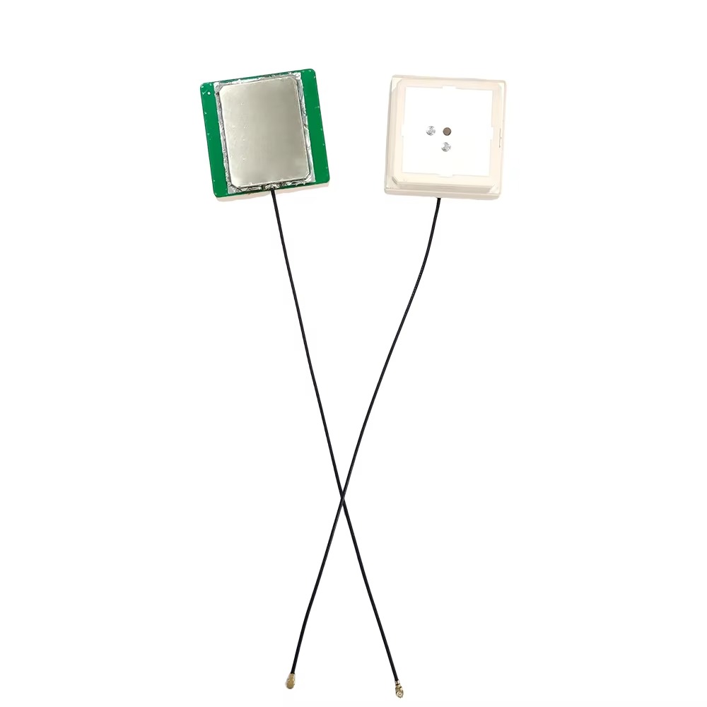
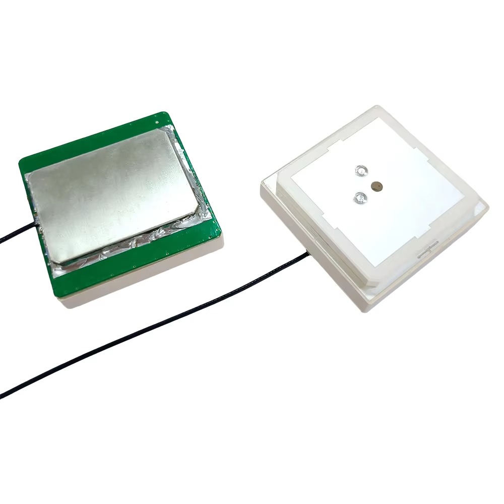
The most common and effective type of element for high-precision antennas is the microstrip patch antenna. This consists of a flat rectangular "patch" of conductive material, separated from a larger ground plane by a dielectric substrate. Its advantages include a low profile, ruggedness, and ease of manufacture. However, a single patch has limitations, particularly a gain pattern that is not ideal for rejecting low-angle multipath. To overcome this, manufacturers use antenna arrays—multiple patch elements arranged in a specific pattern (often a circle, known as a pinwheel design). By carefully controlling the phase of the signal fed to each element, they can electronically "shape" the radiation pattern to enhance performance.
The single most important external feature of a high-end RTK antenna is the choke ring ground plane. This is not merely a flat plate but a series of concentric, corrugated metal rings surrounding the central antenna array. The depth and spacing of these rings are precisely calculated to be approximately one-quarter of the wavelength of the target GPS frequencies. This creates a high-impedance surface that acts as an "electromagnetic choke." For signals arriving at low angles (which are typically multipath reflections from the ground), the choke ring presents a barrier, causing the signal to be reflected again and effectively cancelled out. For signals arriving from above (the direct satellite signals), the rings are virtually invisible. This results in a radiation pattern that is amplified towards the sky and severely attenuated towards the ground—the perfect characteristic for multipath mitigation.
At the very heart of the antenna lies the radome. This is the protective dome, typically made of fiberglass or a proprietary plastic composite, that encloses the sensitive internal components. The radome must be mechanically strong to protect against impact and weather, but it must also be electromagnetically transparent. Its material and shape are carefully chosen to have minimal effect on the incoming radio waves. Any imperfection or water ingress into the radome can alter its dielectric properties, distorting the signals and destabilizing the phase center, leading to significant measurement errors.
Internally, the antenna contains a Low-Noise Amplifier (LNA). This is a critical active component located as close to the antenna elements as possible. Its job is to amplify the incredibly weak satellite signals (which are often buried in thermal noise) before they travel down the coaxial cable to the receiver. A high-quality LNA has two key characteristics: very high gain (to boost the signal) and very low noise figure (meaning it adds minimal additional noise of its own). The LNA is powered by sending a DC voltage up the same coaxial cable from the receiver, a system known as "phantom power" or bias-T power.
The physical construction is also designed to ensure Phase Center Stability. The mechanical and electrical components must be fixed rigidly and made from materials with low thermal expansion coefficients. As the antenna heats up in the sun or cools at night, its physical dimensions change slightly. If not managed, this thermal drift can cause the electrical phase center to move, introducing measurement error. High-quality antennas are designed to be thermally stable, often through symmetric construction and material choice, and they come with a precise calibration file that maps the remaining Phase Center Variations (PCV) as a function of elevation and azimuth for each frequency.
This calibration file, often in the ANTEX (ANTenna EXchange) format, is provided by the manufacturer and is derived from highly precise measurements in an anechoic chamber or via field calibration. Modern GNSS receivers automatically apply these corrections to the raw measurements, mathematically moving the reference point to the antenna's calibrated average phase center. Without applying this file, even the best antenna can introduce several centimeters of error.
Finally, the antenna is equipped with a robust mounting system. This typically includes a 5/8"-11 thread, the standard for survey equipment, allowing it to be securely attached to a tripod, pole, or permanent monument. The connection must be solid and immovable, as any shift in the antenna's position, no matter how small, invalidates the measurements. The entire design—from the choke rings and radome down to the internal amplifiers and physical mounts—is a symphony of engineering all directed towards preserving the integrity of that one, infinitesimally small point in space: the phase center.
To understand how an RTK antenna works, one must first appreciate what it is receiving. GNSS satellites transmit microwave signals on several dedicated frequencies (e.g., GPS L1 at 1575.42 MHz and L2 at 1227.60 MHz). These signals are modulated with two primary components: the Precise (P) Code (or the newer civil codes like L2C and L5) and the Coarse/Acquisition (C/A) Code. Crucially, both codes are modulated onto a fundamental carrier wave. The code is used for calculating the approximate distance to the satellite (the pseudorange), but it is the measurement of the phase of the carrier wave itself that enables centimeter-level accuracy.
The primary function of the antenna is to act as a transducer for these signals. The electromagnetic waves from the satellites induce tiny, oscillating electrical currents in the antenna's conductive elements. Due to the pinwheel or array design, the antenna exhibits directional selectivity. It is most sensitive to signals arriving from above the horizon and exhibits low gain (rejection) to signals from below, which are likely multipath. The choke ring ground plane enhances this effect by creating a null zone for low-elevation signals.
The captured signals from all visible satellites are combined within the antenna structure and passed to the Low-Noise Amplifier (LNA). The LNA's role is critical because the satellite signals are extremely weak, typically around -130 dBm (decibels relative to one milliwatt). By the time these signals travel down a cable to the receiver, cable loss can further attenuate them. The LNA provides enough gain (e.g., 25-40 dB) to overcome this cable loss and ensure the signal is strong enough for the receiver to process without being overwhelmed by the receiver's own internal noise. The quality of the LNA directly impacts the receiver's ability to maintain a lock on satellites in challenging environments, such as under light foliage.
The amplified RF signal is then sent down the coaxial cable to the GNSS receiver. The receiver's first stage is a down-converter, which shifts the high-frequency satellite signals to a lower, intermediate frequency (IF) that is easier to process digitally. Using internal replica codes, the receiver performs correlation, sliding its replica of the C/A code until it synchronizes with the incoming code from the satellite. This process acquires the satellite and provides a coarse pseudorange measurement.
However, for RTK, the magic lies in the next step: carrier-phase tracking. The receiver employs a phase-locked loop (PLL) to lock onto the precise phase of the carrier wave of the incoming satellite signal. It can measure the phase of its internally generated carrier wave against the phase of the received carrier wave. The initial measurement is ambiguous—the receiver can measure the fractional part of a wavelength perfectly, but it does not know the integer number of full wavelengths between the satellite and the antenna. This is the famous integer ambiguity (N).
This is where the RTK system comes into play. A stationary base station antenna, set up over a known point, makes the same set of carrier-phase measurements. Because its position is known exactly, it can calculate what the true carrier-phase measurement should be. The difference between the measured phase and the calculated phase is the error. This error, caused by satellite clock drift, orbital errors, and atmospheric delays (ionosphere and troposphere), is highly correlated over distance.
The base station receiver packages these error corrections and transmits them to the roving surveyor's receiver via a radio link. The rover receiver then applies these corrections to its own raw carrier-phase measurements. With the errors significantly mitigated, the rover can resolve the integer ambiguities (N) for each satellite pair through a statistical process. Once the integers are "fixed," the rover's position can be computed relative to the base station with breathtaking accuracy—often to within 1 cm + 1 ppm (parts per million) of the baseline length.
Throughout this entire process, the antenna's performance is paramount. Any instability in its phase center directly corrupts the carrier-phase measurement. If the electrical point being measured moves, the receiver cannot distinguish this movement from an actual movement of the antenna in space. Similarly, any multipath that the antenna fails to reject creates a distorted signal, causing an error in the phase measurement that the RTK corrections cannot fix, as multipath is local to each antenna. The antenna, therefore, is not a passive component but the very source of the fundamental observable—the carrier phase—that RTK relies upon. Its quality determines the purity of that observable.
The advantages of using a properly designed RTK antenna are the very enablers of modern high-precision surveying. However, these advantages are contingent on overcoming significant technical and practical challenges. Understanding both sides is key to successful field deployment.
Advantages:
Unmatched Accuracy: The primary advantage is the enabling of centimeter-level real-time positioning. This accuracy transforms surveying, construction, and mapping, allowing for precise stakeout, machine control, and as-built verification without the need for post-processing.
Robust Multipath Rejection: Advanced designs like choke rings and controlled radiation pattern arrays (CRPA) provide a significant defensive advantage against one of the most pernicious sources of error in GNSS. This allows surveyors to work closer to buildings, vehicles, and other reflective surfaces with greater confidence.
Improved Signal Reception and Satellite Tracking: High-gain LNAs and optimized elements ensure the receiver can maintain lock on satellites even in suboptimal conditions, such as under light tree cover or in urban canyons. Multi-band support further enhances this by providing more signals to track, increasing redundancy and reliability.
Faster Initialization and Ambiguity Resolution: A stable phase center and low noise figure contribute to cleaner, less noisy data. This allows the receiver's processing engine to resolve the integer ambiguities more quickly and reliably, reducing the time the surveyor spends waiting for a "fixed" RTK solution.
Calibration and Repeatability: The provision of an accurate ANTEX calibration file means that measurements are referenced to a known, consistent point. This allows for repeatable surveys over time, even if different antennas or receivers are used, as long as the calibration is properly applied.
Challenges and Limitations:
Cost: Geodetic-grade RTK antennas are expensive. The sophisticated engineering, precision manufacturing, and rigorous calibration processes involved make them a significant investment, often costing several thousand dollars, sometimes more than the receiver itself. This is a primary barrier to entry.
Size and Weight: Performance often comes at the expense of portability. A full choke ring antenna is large, bulky, and heavy compared to a simple patch antenna. While more compact "pinwheel" designs have mitigated this, the most performant antennas are still substantial objects to mount on a survey pole, potentially leading to user fatigue.
Phase Center Calibration and Management: The necessity of applying a phase center calibration file adds a layer of complexity. If the wrong file is used, or if the file is not applied at all, the antenna will introduce systematic errors of several centimeters. Users must be diligent in ensuring their field software is configured with the correct model for their specific antenna.
Multipath is Not Eliminated: While greatly reduced, multipath rejection is never perfect. Very strong multipath from nearby reflective surfaces (e.g., a large glass building or a body of water) can still penetrate the antenna's defenses. The antenna cannot mitigate multipath affecting the base station, which would then be transmitted to the rover.
Environmental and Physical Vulnerabilities: The antenna is exposed to the elements. While the radome is robust, it can be damaged by impact. Moisture ingress, either through a cracked radome or a poorly sealed cable connection, can drastically alter the antenna's performance and destroy its calibration. Thermal stability, while designed for, can still be a factor in extreme temperature gradients.
Calibration Drift: Over a long period, the physical characteristics of an antenna may change slightly due to aging materials or minor physical shocks. While stable, they are not immutable. For the most critical applications, antennas may need to be re-calibrated periodically, a costly and specialized process.
In essence, the high-performance RTK antenna solves the major physical signal capture problems but introduces logistical and management challenges. The advantages provide the accuracy, but the challenges require the surveyor to be knowledgeable, meticulous, and proactive in equipment setup and data management to fully realize that accuracy in the field.
The application of GPS RTK antennas has moved far beyond its traditional roots in geodetic control surveys. The democratization of centimeter-accurate positioning has revolutionized numerous industries, each leveraging the stable foundation provided by the antenna.
Applications:
Classical Land Surveying: Establishing control networks, topographic surveying, boundary surveys, and construction layout. This is the core application where reliability and absolute accuracy are paramount.
Construction Machine Control (CMC): Antennas are mounted on bulldozers, graders, and excavators. The machine's blade or bucket position is known in real-time relative to a digital design model, allowing operators to grade to precise specifications without stakes, saving immense time and material.
Precision Agriculture: RTK-guided tractors can drive with 2-3 cm accuracy, enabling automated farming practices like precision planting, fertilizing, and harvesting. This reduces overlap, saves inputs, and increases yield. Here, antennas must be ruggedized for the harsh agricultural environment.
Unmanned Aerial Vehicles (UAVs) / Drones: PPK (Post-Processed Kinematic) and RTK drones use small, lightweight, but highly performant antennas to geotag aerial imagery with centimeter-level accuracy. This eliminates the need for numerous ground control points and enables the rapid creation of highly accurate digital surface models and orthomosaics.
Autonomous Vehicles and Robotics: The development of self-driving cars and outdoor robots relies on GNSS for absolute positioning. RTK provides the necessary accuracy, and specialized multi-band antennas are a key sensor in the sensor fusion system.
Monitoring and Deformation Studies: Arrays of permanent RTK antennas are installed on critical infrastructure like dams, bridges, volcanoes, and landslides. By monitoring their relative positions over time, engineers can detect millimeter-level movements that signal potential failure.
Future Trends:
The future of RTK antenna technology is driven by demands for higher performance, miniaturization, integration, and robustness.
Multi-Constellation, Multi-Frequency Support as Standard: Future antennas will be designed to efficiently receive all current and planned signals from all four major GNSS constellations and augmentation systems (e.g., SBAS). This will maximize satellite availability and further improve reliability in challenging environments.
Advanced Multipath Mitigation: Research continues into new techniques for multipath rejection. This includes adaptive antenna arrays that can electronically "steer" nulls in their radiation pattern towards sources of interference and multipath, and advanced signal processing techniques that can identify and filter reflected signals within the receiver.
Miniaturization of High-Performance Designs: The challenge is to pack the performance of a choke ring into a smaller form factor. This involves using metamaterials—artificial materials engineered to have electromagnetic properties not found in nature—to create high-impedance surfaces that mimic choke rings but are much thinner and lighter. This is critical for drones and consumer applications.
Tighter Integration with IMUs and Sensors: The future lies in sensor fusion. We will see more tightly integrated packages combining a multi-band GNSS antenna with an Inertial Measurement Unit (IMU), cameras, and other sensors on a single board. This provides continuous positioning even during GNSS outages (e.g., in tunnels or under heavy cover) and simplifies system design for OEMs.
Improved Robustness and Calibration: Materials science will lead to more durable radomes and more thermally stable internal structures. Furthermore, the process of antenna calibration may become more accessible or even automated, perhaps through crowd-sourced data or onboard calibration routines.
AI-Enhanced Performance: Artificial intelligence could be used to model an antenna's performance in real-time based on the signals it receives, dynamically adjusting processing parameters to optimize for multipath or interference in its immediate environment.
The trajectory is clear: RTK antenna technology will continue to become more capable, more compact, and more integrated, powering the next wave of autonomous systems and precision applications we have yet to imagine.
Conclusion
In the sophisticated ecosystem of RTK positioning, it is easy to focus on the visible technology—the data collector screen, the receiver box, the radio modem. However, this series has underscored the profound truth that the antenna, often a silent and static component, is the true foundation upon which the entire edifice of centimeter accuracy is built. It is the critical first link in the chain, the gatekeeper of the signals that form the raw material for all subsequent processing.
A high-quality geodetic antenna is not merely a collector of signals; it is an intelligent filter and amplifier. Its design—from the choke rings and radome to the LNA and phased array elements—is a direct response to the physical challenges of capturing faint signals from distant satellites while operating in an electrically noisy and reflective environment. Its most precious property is a stable and well-calibrated phase center, providing a trustworthy reference point for the exquisitely precise carrier-phase measurements that are the lifeblood of RTK.
While the antenna confers tremendous advantages in accuracy, multipath rejection, and reliability, it also demands respect and understanding from the user. Its cost, size, and the absolute necessity of proper calibration are non-negotiable aspects of its operation. Neglecting the antenna's requirements is to undermine the entire survey before it even begins.
As technology advances, the antenna will continue to evolve, becoming smaller, smarter, and more integrated. It will be a key enabler for the autonomous future, from self-driving vehicles to intelligent farming and construction equipment. Yet, its core mission will remain unchanged: to faithfully transduce electromagnetic waves into a clean electrical signal, providing a fixed point in a changing world from which all else can be measured. In the pursuit of precision, the investment in and understanding of the GPS RTK antenna is, therefore, the most fundamental investment a surveyor can make.

 86 0755 2819 9597
Lucy Yang | lucy.y@toxutech.com
Nicole Li | nicole@toxutech.com
Dotty Zhao | sales04@toxutech.com
Global Business Director / Sales Team / Global Operations


 En
En Cn
Cn Korean
 Home >


