

-
Products -PCBA Manufacturing RF Connectors RF Cable Assemblys Embedded Antennas External Antennas Positioning Chips and Modules
RF Connectors

RF Cable Assemblys
Embedded Antennas
External Antennas
Positioning Chips and Modules


 Language


Language


Global Positioning System (GPS) is a satellite - based navigation system that provides location and time information in all weather conditions, anywhere on or near the Earth where there is an unobstructed line of sight to four or more GPS satellites. Real - Time Kinematic (RTK) is an advanced GPS technique that significantly improves the accuracy of position determination.
1.1 Introduction to GPS RTK Technology
Global Positioning System (GPS) is a satellite - based navigation system that provides location and time information in all weather conditions, anywhere on or near the Earth where there is an unobstructed line of sight to four or more GPS satellites. Real - Time Kinematic (RTK) is an advanced GPS technique that significantly improves the accuracy of position determination.
In traditional GPS, the accuracy is typically in the range of several meters. However, RTK technology can achieve centimeter - level accuracy. It works by using a reference station at a known location to measure the GPS signals. The reference station then transmits the difference between the measured signals and the known values (correction data) to a rover station (the device whose position is being determined) in real - time. The rover station uses this correction data to adjust its own GPS measurements, thereby achieving high - precision positioning.
1.2 Role of Ceramic Patch Antennas in GPS RTK Systems
Ceramic patch antennas play a crucial role in GPS RTK systems. They are responsible for receiving the weak GPS signals from satellites. The ceramic material used in these antennas has several advantages. Firstly, ceramic has a high dielectric constant, which allows for a more compact antenna design. This is important as GPS RTK devices are often used in applications where size and weight are critical, such as in unmanned aerial vehicles (UAVs), mobile mapping systems, and precision agriculture equipment.
Secondly, ceramic patch antennas offer good radiation efficiency and a relatively stable performance over a wide range of environmental conditions. They can operate effectively in different temperatures, humidity levels, and electromagnetic interference (EMI) environments. In GPS RTK applications, where reliable signal reception is essential for accurate positioning, the stable performance of ceramic patch antennas is highly valued.
Moreover, the patch antenna design, with its flat and planar structure, is easy to integrate into printed circuit boards (PCBs) of GPS RTK receivers. This makes it possible to create compact and lightweight GPS RTK devices that can be easily deployed in various applications.
1.3 Market and Application Landscape
The market for GPS RTK ceramic patch antennas has been growing steadily in recent years, driven by the increasing demand for high - precision positioning in multiple industries.
In the surveying and mapping industry, GPS RTK technology, along with ceramic patch antennas, has become the standard for creating accurate maps. Surveyors can use handheld or vehicle - mounted GPS RTK devices with ceramic patch antennas to precisely measure land boundaries, elevation levels, and topographical features. This has significantly improved the efficiency and accuracy of surveying operations compared to traditional methods.
The agriculture sector is also a major user of GPS RTK ceramic patch antennas. Precision agriculture techniques rely on high - accuracy positioning to optimize farming operations. Tractors and other agricultural machinery equipped with GPS RTK systems can be guided with centimeter - level accuracy, enabling more precise planting, fertilizing, and harvesting. This not only increases crop yields but also reduces the use of resources such as water, fertilizers, and pesticides.
In the construction industry, GPS RTK ceramic patch antennas are used in equipment such as bulldozers, excavators, and graders. The high - precision positioning allows for more accurate grading of land, alignment of structures, and control of construction processes. This helps to improve the quality of construction projects and reduce construction time and costs.
The automotive industry is also showing a growing interest in GPS RTK technology for advanced driver - assistance systems (ADAS) and autonomous driving. Ceramic patch antennas can be integrated into vehicles to provide accurate positioning information, which is crucial for functions such as lane - keeping assist, adaptive cruise control, and self - driving navigation.
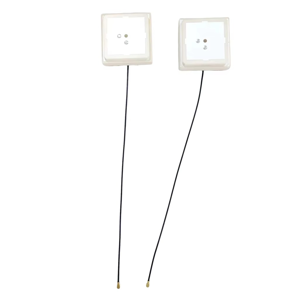
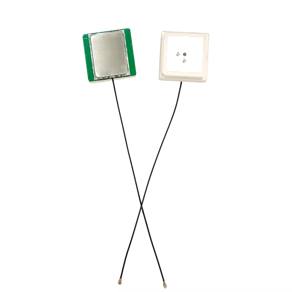
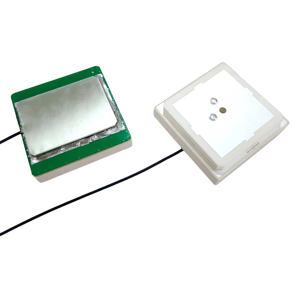
2.1 Components of a GPS RTK Ceramic Patch Antenna
A typical GPS RTK ceramic patch antenna consists of several key components. The main part is the ceramic substrate, which serves as the foundation for the antenna structure. The ceramic material, usually with a high dielectric constant (in the range of 30 - 100 for common ceramic materials used in antennas), helps to reduce the size of the antenna while maintaining good electrical performance.
On top of the ceramic substrate, there is a conductive patch. This patch is typically made of a metal such as copper or silver. The shape of the patch can vary, but rectangular and circular shapes are the most common. The dimensions of the patch are carefully designed based on the operating frequency of the antenna. For GPS applications, which mainly operate in the L - band (e.g., L1 at 1575.42 MHz and L2 at 1227.6 MHz), the patch dimensions are calculated to resonate at these frequencies.
The antenna also includes a feed mechanism. This can be a coaxial cable or a microstrip line. The feed is responsible for delivering the received RF signals from the patch to the GPS RTK receiver. In some designs, a matching network may be included between the feed and the patch to optimize the transfer of power and minimize signal reflection.
In addition, some GPS RTK ceramic patch antennas may have a ground plane. The ground plane can be a separate metal layer on the PCB or a metal structure adjacent to the antenna. The ground plane helps to improve the radiation pattern and efficiency of the antenna.
2.2 Design Considerations for High - Precision Applications
For high - precision GPS RTK applications, several design factors need to be carefully considered. One of the most important is the antenna's bandwidth. A wider bandwidth allows the antenna to receive signals from multiple satellite constellations and different frequency bands more effectively. In modern GPS RTK systems, in addition to the traditional GPS L1 and L2 bands, signals from other satellite navigation systems such as GLONASS, Galileo, and BeiDou are also utilized. An antenna with a wide bandwidth can capture these diverse signals, enabling better positioning accuracy.
The radiation pattern of the antenna is also crucial. In GPS RTK applications, a hemispherical radiation pattern is often desired. This pattern allows the antenna to receive signals from satellites located in different directions in the sky. The elevation and azimuth angles of the radiation pattern need to be optimized to ensure good signal reception in various operating environments. For example, in urban canyons or areas with tall buildings, the antenna should be able to receive signals from satellites that are at lower elevation angles.
Another important consideration is the antenna's gain. High - gain antennas can capture weaker signals more effectively, which is essential for GPS RTK systems, especially when the satellite signals are obstructed or attenuated. However, increasing the gain may also lead to a more directive radiation pattern, so a balance needs to be struck between gain and radiation pattern coverage.
The mechanical design of the antenna is also significant. The antenna should be rugged enough to withstand the harsh environmental conditions of its intended applications. This includes resistance to temperature variations, humidity, vibration, and shock. In applications such as UAVs or mobile mapping in rough terrains, the antenna must be able to maintain its performance under these challenging conditions.
2.3 Manufacturing Processes for Ceramic Patch Antennas
The manufacturing of GPS RTK ceramic patch antennas involves several steps. First, the ceramic substrate is prepared. This may involve processes such as ceramic powder mixing, shaping (e.g., by pressing or injection molding), and sintering. Sintering is a crucial step where the ceramic material is heated to a high temperature to densify it and improve its mechanical and electrical properties.
Next, the conductive patch is formed on the ceramic substrate. This can be done through methods such as screen printing, sputtering, or chemical vapor deposition (CVD). Screen printing is a commonly used method, where a conductive ink (usually containing metal particles) is printed onto the ceramic substrate in the desired patch shape. After printing, the ink is cured to form a solid conductive patch.
The feed mechanism and any additional components such as matching networks are then attached to the antenna. If a coaxial cable is used as the feed, it is carefully soldered or crimped to the appropriate connection points on the antenna. For microstrip line feeds, the microstrip lines are fabricated on the PCB along with the antenna using standard PCB manufacturing processes.
Finally, the completed antenna may undergo testing and calibration to ensure that it meets the required performance specifications. This includes testing for parameters such as resonance frequency, bandwidth, gain, and radiation pattern. Any necessary adjustments or re - work may be carried out based on the test results.
3.1 Signal Reception
High - precision GPS RTK ceramic patch antennas work by receiving signals from multiple satellites in the GPS or other satellite constellations. The antenna is designed to be sensitive to the weak electromagnetic signals transmitted by the satellites. These signals carry information about the satellite's position, time, and other parameters.
The patch elements of the antenna act as transducers, converting the unguided electromagnetic waves from the satellites into guided electromagnetic waves that can be processed by the receiver. The ceramic material of the patch helps in this conversion process due to its dielectric properties. The antenna is designed to receive circularly polarized signals, typically right - handed circular polarization (RHCP). This polarization type is beneficial as it helps in rejecting multipath fading and interference. In an environment where there are reflections of the satellite signals from buildings, terrain, or other objects, these reflected signals can cause interference. The RHCP polarization of the antenna allows it to preferentially receive the direct signal from the satellite and reject the cross - polarized reflected signals, thus improving the signal strength and the accuracy of the received signal.
3.2 RTK Error Correction
In the context of RTK, the antenna works in conjunction with a reference station. The reference station, which has a known accurate location, also has an antenna to receive the satellite signals. The reference station measures the errors in the GPS signals, such as satellite position errors, clock/timing errors, and estimations of degradation parameters. These errors are then transmitted to the rover station, which has the high - precision GPS RTK ceramic patch antenna.
The rover antenna receives both the satellite signals and the error correction data from the reference station. The receiver at the rover uses this error correction data to adjust the position calculation based on the received satellite signals. By comparing the measured signals from the satellites with the known errors provided by the reference station, the rover can achieve centimeter - level accuracy in its position determination. This process is crucial for applications that require high precision, such as surveying, where accurate mapping of land features is essential.
3.1 Electromagnetic Wave Reception by the Patch Antenna
When GPS satellites transmit signals, these signals propagate through space as electromagnetic waves. A GPS RTK ceramic patch antenna is designed to receive these electromagnetic waves. The conductive patch on the ceramic substrate acts as an antenna element that interacts with the incoming electromagnetic fields.
According to the principles of electromagnetics, when an electromagnetic wave impinges on the conductive patch, it induces an electric current on the patch surface. The magnitude and distribution of this induced current depend on the characteristics of the incoming wave, such as its frequency, polarization, and angle of incidence. The ceramic substrate, with its high dielectric constant, affects the behavior of the electromagnetic fields around the patch. It helps to confine and guide the electromagnetic fields, enhancing the antenna's ability to capture the incoming signals.
The induced current on the patch is then converted into an electrical signal that can be processed by the GPS RTK receiver. This conversion occurs at the feed point of the antenna, where the feed mechanism (such as a coaxial cable or microstrip line) is connected to the patch. The electrical signal at the feed point contains information about the amplitude, phase, and frequency of the received electromagnetic wave, which is crucial for the subsequent signal processing in the GPS RTK system.
3.2 Interaction with GPS Satellite Signals
GPS satellites transmit signals at specific frequencies and with specific modulation schemes. The L1 frequency (1575.42 MHz) is the most commonly used frequency for civilian GPS applications and contains the Coarse/Acquisition (C/A) code and the Precise (P) code. The L2 frequency (1227.6 MHz) is mainly used for military and more precise positioning applications and also carries the P code and other signals.
A GPS RTK ceramic patch antenna is designed to be sensitive to these GPS frequencies. The antenna's resonant frequency is tuned to match the GPS signal frequencies, so that it can efficiently capture the signals. When the antenna receives the GPS signals, it not only detects the carrier frequency but also the modulation information carried on the carrier.
In GPS RTK systems, the reference station and the rover station both use ceramic patch antennas to receive the GPS satellite signals. The reference station, located at a known position, measures the received signals and calculates the difference between the measured signals and the known values based on its known location. This difference, which represents the errors in the received signals (such as satellite clock errors, atmospheric delays, and ephemeris errors), is then transmitted as correction data to the rover station.
The rover station, using its own ceramic patch antenna, receives both the GPS satellite signals and the correction data from the reference station. By applying the correction data to its own received signals, the rover station can accurately determine its position relative to the reference station, achieving high - precision positioning.
3.3 Signal Processing in GPS RTK Systems
Once the GPS RTK ceramic patch antenna receives the signals, the signal processing in the GPS RTK system begins. The first step is usually signal amplification. The received GPS signals are very weak, typically in the range of - 130 dBm to - 160 dBm, so they need to be amplified to a level that can be processed by the subsequent components. Low - Noise Amplifiers (LNAs) are commonly used for this purpose to amplify the signals while adding as little noise as possible.
After amplification, the signals are filtered to remove unwanted noise and interference. Band - pass filters are used to select the GPS frequency bands of interest and reject signals outside these bands. Then, the signals are demodulated to extract the navigation data, which includes information about the satellite's position (ephemeris), clock correction, and other parameters.
In the case of RTK, the rover station combines the received GPS signals with the correction data from the reference station. This is typically done through a process called carrier - phase differencing. By comparing the carrier phases of the signals received at the rover and the reference station, the rover station can calculate the precise distance (pseudorange) between itself and the satellites. Using this information along with the known position of the reference station, the rover station can determine its own position with centimeter - level accuracy.
The signal processing also involves tasks such as satellite tracking, which ensures that the GPS receiver can continuously monitor the signals from the satellites even as the user's position and the satellite's positions change. Advanced algorithms are used to optimize the signal processing and improve the accuracy and reliability of the GPS RTK positioning.
5.1 Current Applications in Various Industries
5.1.1 Surveying and Mapping
In the surveying and mapping industry, GPS RTK ceramic patch antennas are extensively used. Traditional surveying methods, such as using total stations and theodolites, are time - consuming and require line - of - sight between measurement points. GPS RTK technology, with its ceramic patch antennas, has revolutionized this field. Surveyors can now cover large areas more quickly and accurately.
For example, in land surveying, GPS RTK devices with ceramic patch antennas can precisely measure property boundaries, topographical features, and elevation levels. The high - precision positioning allows for the creation of highly detailed and accurate maps. In hydrographic surveying, which involves mapping the underwater terrain, GPS RTK ceramic patch antennas are used in combination with sonar systems. The accurate positioning provided by theantenna ensures that the sonar data is accurately georeferenced, enabling the creation of precise underwater maps for navigation, resource exploration, and environmental monitoring. In aerial surveying, UAVs equipped with GPS RTK ceramic patch antennas can capture high - resolution aerial images while maintaining precise position information for each image. This allows for the generation of detailed 3D models of the terrain, which are widely used in urban planning, disaster assessment, and infrastructure development.
5.1.2 Precision Agriculture
The application of GPS RTK ceramic patch antennas in precision agriculture has transformed the way farming operations are conducted. In modern agriculture, maximizing crop yields while minimizing resource waste is a top priority, and high - precision positioning plays a key role in achieving this goal.
Tractors and harvesters equipped with GPS RTK systems and ceramic patch antennas can be guided along pre - determined paths with centimeter - level accuracy. This enables precise planting, where seeds are sown at the optimal spacing and depth. For example, in corn farming, the accurate guidance ensures that each seed is planted in a straight line and at the correct distance from neighboring seeds, which promotes uniform growth and reduces competition for resources such as sunlight, water, and nutrients.
Fertilizer and pesticide application is another area where GPS RTK ceramic patch antennas are highly valuable. By using the precise positioning information, farmers can apply fertilizers and pesticides only to the areas that need them. This is done by creating variable - rate application maps based on soil nutrient levels, crop health, and other factors. The agricultural machinery, guided by the GPS RTK system, adjusts the application rate in real - time as it moves across the field. This not only reduces the cost of fertilizers and pesticides but also minimizes the environmental impact by preventing over - application, which can lead to soil and water pollution.
Irrigation management is also improved with the use of GPS RTK ceramic patch antennas. Precision irrigation systems can be integrated with GPS RTK technology to deliver water precisely to the root zones of the crops. By knowing the exact position of each area of the field, farmers can control the irrigation amount and timing more accurately, ensuring that the crops receive the right amount of water when they need it. This helps to conserve water resources and improve crop water use efficiency.
5.1.3 Construction and Infrastructure Development
In the construction industry, the demand for high - precision positioning to ensure the quality and efficiency of construction projects has led to the widespread use of GPS RTK ceramic patch antennas. Construction equipment such as bulldozers, excavators, graders, and pavers are now commonly equipped with GPS RTK systems.
During the site preparation phase, GPS RTK ceramic patch antennas enable accurate grading of the land. Graders equipped with the technology can precisely level the ground to the required elevation, ensuring that the foundation of the structure is built on a stable and even surface. This reduces the risk of structural problems in the future and saves time and costs associated with rework.
In road construction, GPS RTK ceramic patch antennas are used to control the paving process. Pavers can be guided to lay asphalt or concrete with precise thickness and slope. The high - precision positioning ensures that the road surface is smooth and meets the design specifications, which improves the durability and safety of the road. Additionally, the accurate positioning of construction equipment helps to optimize the use of materials, reducing waste and lowering construction costs.
For large - scale infrastructure projects such as bridges and tunnels, GPS RTK ceramic patch antennas are used to monitor the construction process and ensure that the components are installed in the correct position. Surveyors can use handheld GPS RTK devices with ceramic patch antennas to measure the position of structural elements, such as bridge girders or tunnel segments, and compare them to the design plans. Any deviations can be detected and corrected in a timely manner, ensuring the structural integrity of the project.
5.1.4 Automotive and Transportation
The automotive industry is increasingly adopting GPS RTK technology with ceramic patch antennas to support advanced driver - assistance systems (ADAS) and the development of autonomous driving.
ADAS features such as lane - keeping assist, adaptive cruise control, and automatic emergency braking rely on accurate positioning information to function properly. GPS RTK ceramic patch antennas provide the high - precision positioning needed to determine the vehicle's exact position relative to the road lanes, other vehicles, and road infrastructure. For example, lane - keeping assist systems use the positioning data to detect if the vehicle is drifting out of its lane and provide corrective steering inputs to keep the vehicle on track.
In the development of autonomous driving, GPS RTK ceramic patch antennas are essential for enabling the vehicle to navigate safely and accurately. Autonomous vehicles need to know their position with centimeter - level accuracy to make decisions such as turning, changing lanes, and avoiding obstacles. The combination of GPS RTK technology and ceramic patch antennas, along with other sensors such as LiDAR, radar, and cameras, provides a comprehensive perception and navigation system for autonomous vehicles.
In the transportation sector, GPS RTK ceramic patch antennas are also used in fleet management. Logistics companies can track the position of their vehicles in real - time with high accuracy, allowing them to optimize route planning, improve delivery efficiency, and monitor driver behavior. The precise positioning information helps to reduce fuel consumption, minimize delivery delays, and enhance the overall productivity of the fleet.
5.2 Future Trends in GPS RTK Ceramic Patch Antenna Technology
5.2.1 Multi - Constellation and Multi - Frequency Support
One of the key future trends in GPS RTK ceramic patch antenna technology is the increased support for multiple satellite constellations and frequency bands. Currently, GPS RTK systems mainly use signals from the GPS constellation, but with the development of other global navigation satellite systems (GNSS) such as GLONASS (Russia), Galileo (European Union), BeiDou (China), and QZSS (Japan), future ceramic patch antennas will be designed to receive signals from multiple constellations simultaneously.
By supporting multiple constellations, the antenna can access a larger number of satellites, which improves the availability and reliability of positioning, especially in challenging environments such as urban canyons and dense forests. For example, in an urban area where GPS signals may be blocked by tall buildings, signals from GLONASS or BeiDou satellites may still be available, ensuring that the positioning system continues to function.
In addition to multi - constellation support, future ceramic patch antennas will also be designed to operate on multiple frequency bands. GPS uses L1 and L2 bands, while other GNSS systems have their own frequency bands. For instance, Galileo uses E1, E2, and E5 bands, and BeiDou uses B1, B2, and B3 bands. By supporting multiple frequency bands, the antenna can capture more signal information, which helps to reduce the impact of ionospheric and tropospheric delays on positioning accuracy. This will further improve the precision and stability of GPS RTK systems.
5.2.2 Miniaturization and Integration with Other Components
The trend towards miniaturization of electronic devices is driving the development of smaller and more compact GPS RTK ceramic patch antennas. As applications such as wearable devices, small UAVs, and portable surveying equipment require smaller form factors, antenna designers are exploring new materials and design techniques to reduce the size of ceramic patch antennas without compromising their performance.
Advancements in ceramic material technology, such as the development of ceramic materials with even higher dielectric constants, will enable the creation of smaller antennas. Additionally, innovative antenna designs, such as multi - layer ceramic patch antennas or fractal - based patch antennas, can help to reduce the physical size of the antenna while maintaining a wide bandwidth and high gain.
Another future trend is the integration of GPS RTK ceramic patch antennas with other electronic components. For example, antennas may be integrated with low - noise amplifiers (LNAs), filters, and other RF front - end components into a single module. This integration simplifies the design and manufacturing process of GPS RTK devices, reduces the overall size and weight of the device, and improves the performance and reliability of the system by minimizing signal loss between components.
5.2.3 Enhanced Anti - Interference and Anti - Multipath Capabilities
With the increasing number of wireless devices and the growing complexity of the electromagnetic environment, the issue of signal interference and multipath effects is becoming more severe. Future GPS RTK ceramic patch antennas will be equipped with enhanced anti - interference and anti - multipath capabilities to ensure reliable signal reception and high - precision positioning.
In terms of anti - interference, new antenna designs will incorporate techniques such as adaptive beamforming and null steering. Adaptive beamforming allows the antenna to focus its radiation pattern towards the desired satellites, while null steering creates nulls in the radiation pattern towards sources of interference. This helps to reduce the impact of external electromagnetic interference on the received GPS signals.
To address multipath effects, antenna designers are developing new patch shapes and ground plane configurations. For example, the use of chiral structures or metamaterial - based ground planes can help to reduce the reflection of signals from the ground or nearby objects, minimizing the number of multipath signals reaching the antenna. Additionally, signal processing algorithms will be further optimized to detect and eliminate multipath signals during the data processing phase.
5.2.4 Energy Efficiency and Low - Power Operation
As more GPS RTK devices are used in battery - powered applications such as portable surveying instruments, UAVs, and wearable devices, energy efficiency and low - power operation have become important considerations for future ceramic patch antennas.
Future antenna designs will focus on reducing the power consumption of the antenna and the associated RF front - end components. This can be achieved through the use of low - power materials and components, as well as optimized antenna structures that minimize power loss. For example, the use of high - conductivity metals for the patch and feed lines can reduce resistive losses, improving the overall efficiency of the antenna.
In addition, advanced power management techniques will be integrated into GPS RTK systems to optimize the power consumption of the antenna. For instance, the antenna can be put into a low - power sleep mode when not in use, and wake up only when needed to receive satellite signals. This helps to extend the battery life of the device, making it more suitable for long - duration field operations.
Conclusion
6.1 Summary of Key Findings
GPS RTK ceramic patch antennas have emerged as a critical component in enabling high - precision positioning across a wide range of industries. This analysis has highlighted several key findings regarding their overview, design and construction, working principles, advantages and challenges, applications, and future trends.
In terms of overview, GPS RTK technology, when combined with ceramic patch antennas, achieves centimeter - level accuracy by using a reference station to provide real - time correction data to a rover station. Ceramic patch antennas play a vital role in this system by receiving weak GPS signals, and their high dielectric constant, compact design, good environmental adaptability, and easy integration make them well - suited for GPS RTK applications. The market for these antennas is growing, driven by demand from industries such as surveying and mapping, agriculture, construction, and automotive.
The design and construction of GPS RTK ceramic patch antennas involve key components including a ceramic substrate, conductive patch, feed mechanism, and optional ground plane. Design considerations for high - precision applications include bandwidth, radiation pattern, gain, and mechanical ruggedness. Manufacturing processes such as ceramic substrate preparation, conductive patch formation, and component assembly are crucial for ensuring the performance and reliability of the antenna.
The working principles of GPS RTK ceramic patch antennas involve the reception of electromagnetic waves from GPS satellites, the interaction with these signals to induce an electric current, and the subsequent signal processing in the GPS RTK system. Signal amplification, filtering, demodulation, and carrier - phase differencing are key steps in the signal processing chain that enable high - precision positioning.
The advantages of GPS RTK ceramic patch antennas include high - precision positioning, compact and lightweight design, good environmental adaptability, and easy integration. However, they also face challenges such as signal interference and multipath effects, limited bandwidth, dependence on satellite visibility, and the need to balance cost and performance.
Current applications span multiple industries, including surveying and mapping (for land, hydrographic, and aerial surveys), precision agriculture (for planting, fertilization, and irrigation), construction (for site preparation, road construction, and infrastructure projects), and automotive (for ADAS and autonomous driving). Future trends include increased multi - constellation and multi - frequency support, further miniaturization and integration, enhanced anti - interference and anti - multipath capabilities, and improved energy efficiency.
6.2 Significance and Impact
The development and widespread adoption of GPS RTK ceramic patch antennas have had a significant impact on various industries and society as a whole. In the surveying and mapping industry, they have revolutionized the way maps are created, making the process faster, more accurate, and more efficient. This has enabled better urban planning, disaster management, and resource exploration.
In agriculture, the use of GPS RTK ceramic patch antennas has contributed to the development of precision agriculture, which helps to increase crop yields, reduce resource waste, and minimize environmental impact. This is crucial in addressing global food security challenges and promoting sustainable agriculture practices.
In the construction industry, the technology has improved the quality and efficiency of construction projects, reducing costs and ensuring the safety and durability of infrastructure. This supports economic development and the creation of high - quality built environments.
In the automotive industry, GPS RTK ceramic patch antennas are playing a key role in the advancement of ADAS and autonomous driving, which have the potential to reduce traffic accidents, improve traffic flow, and enhance the mobility of people with disabilities.
6.3 Future Outlook
Looking ahead, the future of GPS RTK ceramic patch antenna technology is promising. As the demand for high - precision positioning continues to grow in emerging applications such as smart cities, Internet of Things (IoT), and unmanned systems (including autonomous ships and drones), the development of more advanced ceramic patch antennas will be driven forward.
Research and development efforts will focus on addressing the current challenges, such as improving anti - interference and anti - multipath capabilities, expanding bandwidth to support more satellite constellations and frequency bands, and reducing the size and power consumption of the antennas. Additionally, the integration of GPS RTK ceramic patch antennas with other emerging technologies such as artificial intelligence (AI) and machine learning will further enhance the performance and functionality of GPS RTK systems.
AI - powered signal processing algorithms can be used to better detect and eliminate interference and multipath signals, as well as optimize the satellite tracking and positioning process. Machine learning techniques can also be applied to antenna design, enabling the automatic optimization of antenna parameters for specific applications and environments.
In conclusion, GPS RTK ceramic patch antennas are a key enabler of high - precision positioning technology, with wide - ranging applications and significant potential for future development. As technology continues to advance, they will play an even more important role in shaping the future of various industries and improving the quality of life for people around the world.

 86 0755 2819 9597
Lucy Yang | lucy.y@toxutech.com
Nicole Li | nicole@toxutech.com
Dotty Zhao | sales04@toxutech.com
Global Business Director / Sales Team / Global Operations


 En
En Cn
Cn Korean
 Home >


