

-
Products -PCBA Manufacturing RF Connectors RF Cable Assemblys Embedded Antennas External Antennas Positioning Chips and Modules
RF Connectors

RF Cable Assemblys
Embedded Antennas
External Antennas
Positioning Chips and Modules


 Language


Language


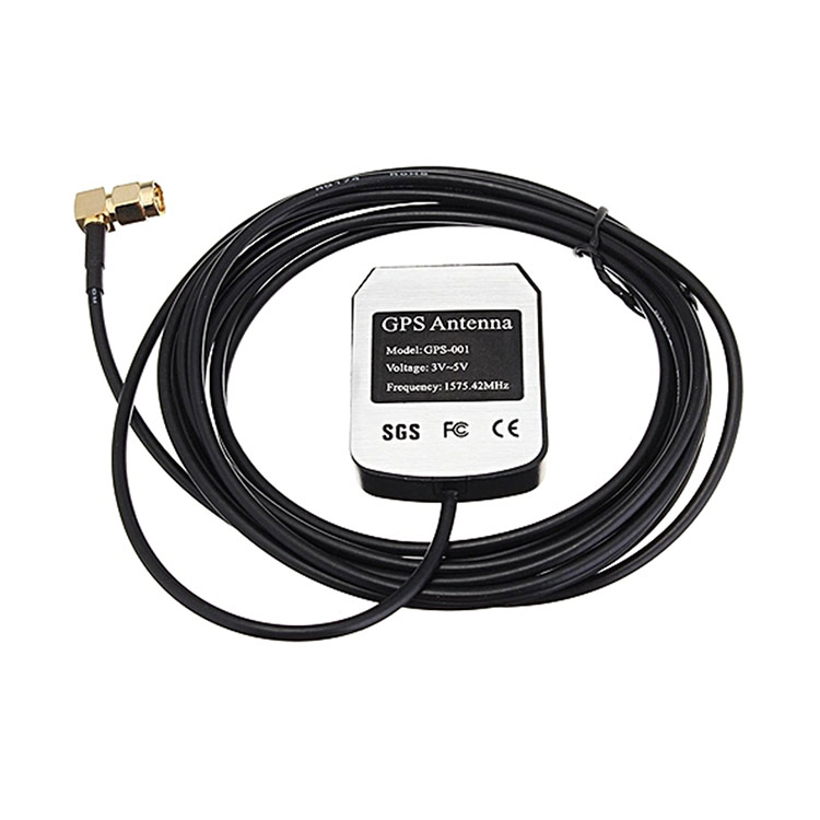

In the vast ecosystem of Global Navigation Satellite Systems (GNSS), the antenna serves as the critical gateway, the first and most vital interface between the digital world of precise positioning and the analog realm of electromagnetic waves traveling from space. A GPS L1/L2 antenna is a specific class of GNSS antenna designed to receive signals on the two primary legacy frequencies used by the United States' Global Positioning System: L1 (1575.42 MHz) and L2 (1227.60 MHz). The inclusion of the "SMA Male connector" specification might seem like a minor detail, but it is a crucial one, defining the physical and electrical interface that integrates this antenna into a larger system. This combination of technical capability and standardized interfacing makes this component a fundamental building block for a wide array of precision applications, from surveying to timing.
The L1 frequency is the civilian workhorse, carrying the Coarse/Acquisition (C/A) code that allows for standard positioning with meter-level accuracy. However, the pursuit of greater precision led to the utilization of the L2 frequency. Initially reserved for military use with the encrypted Precision (P(Y)) code, techniques were developed to leverage the L2 carrier wave without needing to decrypt the code. The ability to receive both L1 and L2 signals is what separates precision-grade antennas from consumer-grade ones. By measuring the delay difference between the two frequencies caused by the ionosphere (the layer of charged particles in the upper atmosphere), a dual-frequency receiver can accurately model and correct for this major source of error. This ionospheric correction is the key to achieving centimeter-level accuracy when used in techniques like Real-Time Kinematic (RTK) or Post-Processed Kinematic (PPK) positioning.
The SMA (SubMiniature version A) connector is a ubiquitous RF coaxial connector known for its robust performance up to 18 GHz, making it ideal for GNSS frequencies. The "male" designation refers to the connector with the center pin. This interface is the industry standard for connecting external antennas to a vast range of equipment, including GPS receivers, data loggers, cellular modems with GPS functionality, and many embedded systems. Its prevalence signifies that this antenna is not a standalone novelty but a interoperable component designed to be plugged into a broader electronic system. The connector ensures a reliable 50-ohm impedance match, minimal signal loss, and a secure mechanical connection that is resistant to vibration—a essential feature for mobile or airborne applications.
The target audience for such an antenna is diverse. It includes surveyors needing base stations or rover antennas, engineers developing precision navigation systems, drone manufacturers integrating PPK capabilities into their platforms, and professionals in agriculture, construction, and GIS. For them, this antenna is not an abstract component but a tangible tool that defines the upper limit of their system's performance. Its design, construction, and electrical characteristics directly influence data quality, reliability, and ultimately, the success of their projects. It represents the perfect marriage of specialized RF functionality—dual-band reception—with a universal, reliable physical interface, making high-precision GNSS technology accessible and deployable across countless fields.
The design and construction of a GPS L1/L2 antenna with an SMA male connector is a sophisticated exercise in electromagnetic engineering, materials science, and precision manufacturing. The goal is to create a device that can efficiently capture two specific microwave frequencies with high fidelity, amplify them without adding distortion, and deliver them through a standardized interface, all while operating reliably in harsh environmental conditions.
The heart of the antenna is the radiating element. For L1/L2 antennas, the most common and effective design is the stacked patch antenna. This design features two separate conductive patches, one resonating for the L1 band and a larger one underneath for the L2 band, separated by a dielectric substrate. This stacked configuration allows a single antenna to operate efficiently across two distinct frequency bands without significant performance compromise. The patches are typically photochemically etched onto a printed circuit board (PCB) made from a low-loss dielectric material like Rogers RO4003, which maintains stable electrical properties across temperature variations. The size, shape, and spacing of these patches are meticulously calculated using advanced electromagnetic simulation software to optimize parameters like gain, bandwidth, and axial ratio.
A critical requirement for precision antennas is a stable phase center. The phase center is the electrical point from which the radiation appears to emanate; it is the virtual reference point for all measurements. For carrier-phase positioning (like RTK), any movement or instability of this point translates directly into measurement error. The stacked patch design, with its symmetrical geometry, is excellent for providing a stable phase center that is consistent across different angles of signal arrival (azimuth and elevation). High-quality antennas undergo rigorous testing in an anechoic chamber to characterize their Phase Center Offset (PCO) and Phase Center Variation (PCV), and this calibration data is often provided in an ANTEX file for users to apply in post-processing software.
Surrounding the patch element is the ground plane. This is a conductive surface, typically a circular or square sheet of metal, that serves as an electrical reflector. It is essential for shaping the antenna's radiation pattern, directing gain towards the sky (where the satellites are) and away from the horizon and ground. This is the antenna's first line of defense against multipath—the phenomenon where signals bounce off the ground or nearby structures before reaching the antenna, causing positioning errors. The size of the ground plane directly influences the antenna's performance; a larger ground plane generally provides better gain at low elevations and superior multipath rejection.
The entire assembly is protected by a radome. This cover is not just a cosmetic shell; it is a critical part of the antenna system. It must be made from a material that is virtually transparent to RF signals at L1 and L2 frequencies, such as high-quality ABS plastic or polycarbonate. It must also be rugged enough to protect the delicate internal components from physical impact, moisture, and UV radiation. A high IP (Ingress Protection) rating, such as IP67, is standard, ensuring the antenna is dust-tight and can withstand temporary immersion in water.
Integrated directly behind the radiating patch, or on a small PCB within the housing, is the Low-Noise Amplifier (LNA). This active component is paramount. Its job is to amplify the incredibly weak signals from space (often as low as -130 dBm) before they travel down the coaxial cable to the receiver. A high-quality LNA has two key characteristics: very high gain (typically 26-40 dB) to overcome cable loss, and an ultra-low noise figure (often < 2 dB) to ensure it amplifies the signal without adding significant electronic noise of its own. The LNA is powered by a DC voltage (typically 3V-5V) supplied from the receiver up the same coaxial cable that carries the amplified signal down, a system known as "phantom power" or bias-T power.
Finally, this entire system is terminated with the SMA male connector. This is a precision-machined component, usually with a gold-plated center pin and outer shell to ensure excellent conductivity and corrosion resistance. The connector is securely attached to the antenna housing and electrically connected to the output of the LNA via a short, high-quality coaxial cable or a direct PCB launch. The robustness of this connection is vital, as it is the sole link between the antenna and the rest of the system.
The operation of a GPS L1/L2 antenna is a process of selective reception, amplification, and delivery. It acts as a transducer and a pre-processor, converting free-space electromagnetic waves into a clean, strengthened electrical signal ready for the complex digital processing performed by the receiver.
The process begins over 20,000 km away, as GPS satellites broadcast faint, right-hand circularly polarized (RHCP) microwave signals on the L1 and L2 carriers. The antenna's stacked patch element is specifically designed to be most sensitive to RHCP signals, which helps to reject reflected signals (which often reverse their polarization) and thus mitigate multipath error. As these waves impinge upon the antenna, they induce tiny oscillating electrical currents in the patch elements. The geometry of the stacked patches ensures that both the 1.575 GHz (L1) and 1.227 GHz (L2) frequencies are resonated efficiently, capturing the energy from both signals simultaneously.
The captured signals are incredibly weak, having traveled a vast distance. They are immediately passed to the Low-Noise Amplifier (LNA). The LNA's primary role is to elevate the signal strength far above the inherent thermal noise floor of the subsequent components, particularly the lossy coaxial cable and the receiver's own internal noise. The "low-noise" aspect is critical; a poor amplifier would drown the faint satellite signals in its own electronic hiss. The high gain ensures that even after the signal suffers attenuation traveling through the cable, it arrives at the receiver at a level strong enough for robust processing.
The amplified signals are then presented to the SMA connector. This connector serves as the gateway, maintaining a consistent 50-ohm impedance match to minimize signal reflections that could cause standing waves and loss of power. A coaxial cable, fitted with a matching SMA female connector, is attached here. This cable carries the amplified RF signals, along with the DC power for the LNA traveling in the opposite direction, to the GPS receiver.
Inside the receiver, the signals are down-converted, filtered, and digitized. The receiver generates replica codes for the C/A code on L1 and, using advanced techniques like semi-codeless or modernized code tracking, for the signals on L2. The most important measurements are the pseudorange (based on the code) and the carrier phase (based on the precise wavelength of the L1 and L2 carriers). The carrier phase measurement is extremely precise but ambiguous, as the receiver doesn't initially know the integer number of wavelengths between the satellite and antenna.
The magic of dual-frequency (L1/L2) operation happens here. The ionosphere delays the GPS signals, an effect that is inversely proportional to the square of the frequency. Therefore, the delay is different for L1 and L2. By comparing the two measured pseudoranges or the two carrier phases, the receiver can precisely calculate the ionospheric delay and remove it from the measurements. This results in a much more accurate "ionosphere-free" solution. This is absolutely essential for high-precision applications, as the ionosphere can introduce errors ranging from several meters to over 20 meters.
Throughout this process, the antenna's role is passive yet fundamental. Its ability to provide a strong, clean, and stable signal—where the phase information is preserved with minimal distortion—directly determines the receiver's ability to quickly acquire satellites, maintain lock, and resolve the integer ambiguities in the carrier phase measurements to achieve centimeter-level accuracy.
The GPS L1/L2 antenna with an SMA connector offers a powerful set of advantages that enable precision, but these are coupled with specific challenges that users must understand and manage.
Advantages:
Ionospheric Error Mitigation: This is the paramount advantage. The ability to receive both L1 and L2 frequencies allows the receiver to calculate and eliminate the single largest source of error in GNSS positioning, enabling decimeter to centimeter-level accuracy.
Faster Integer Ambiguity Resolution: In RTK and PPK systems, the dual-frequency data provides more observables. This allows the receiver's processing engine to resolve the integer ambiguities in the carrier phase measurements more quickly and reliably, reducing initialization time.
Increased Robustness and Redundancy: Having two frequencies provides redundancy. If a satellite's signal on one frequency is temporarily blocked or degraded (e.g., by foliage), the receiver may still maintain lock on the other frequency, preventing a loss of positioning.
Standardized Interfacing: The SMA male connector is a robust, widely adopted standard. This ensures compatibility with a huge range of receivers, cables, and embedded systems, simplifying system integration and component sourcing.
Foundation for Precision: This antenna type forms the essential hardware foundation for all professional-grade GPS applications, including surveying, mapping, machine control, and scientific monitoring. It provides the raw data quality necessary for advanced techniques.
Challenges and Limitations:
Cost and Complexity: L1/L2 antennas are significantly more complex to design and manufacture than single-band L1 antennas. The need for a stacked patch, a high-performance LNA, and rigorous calibration translates to a higher cost.
Size Constraints: The physics of resonating at the lower L2 frequency requires a larger radiating element. While the stacked patch design is efficient, a dual-band antenna will always be larger than a single-band L1 antenna of equivalent quality.
Power Requirements: The integrated LNA requires a source of DC power from the receiver. If the receiver does not provide bias-T power on the antenna port, an external power injector is required, adding complexity to the setup.
Calibration Criticality: For centimeter-level accuracy, the antenna's phase center variations (PCV) must be accounted for. Using the antenna without its specific calibration file can introduce errors of several centimeters. Users must ensure their processing software is configured with the correct model.
Cable Loss Management: While the LNA provides gain, the choice of coaxial cable is still critical. Long or low-quality cables will attenuate the signal. For long runs, a higher-gain antenna or an in-line amplifier may be necessary, which adds cost and another potential point of failure.
Multipath Susceptibility: While the ground plane helps, no antenna is immune to multipath. Performance can be degraded if placed near highly reflective surfaces. The antenna's placement and environment must still be considered.
The GPS L1/L2 antenna is a mature technology that remains deeply embedded in the core of countless precision applications, even as the industry advances towards multi-constellation, multi-frequency systems.
Applications:
Land Surveying: The classic application. Used on RTK base stations and rover poles for establishing control points, topographic mapping, and construction layout.
Precision Agriculture: Guiding tractors for auto-steer and variable rate application (VRA) of seeds, fertilizer, and pesticides.
Unmanned Aerial Vehicles (UAVs): Mounted on drones for PPK/RTK mapping, enabling the creation of highly accurate digital surface models and orthomosaics with minimal ground control.
Machine Guidance and Control: Providing precise location for bulldozers, graders, and excavators on construction and mining sites.
Scientific and Environmental Monitoring: Deployed on permanent stations for monitoring crustal deformation, volcanic activity, and structural health of bridges and dams.
Timing and Synchronization: Used in telecommunications networks and power grids where precise time synchronization is critical, with L2 reception providing robustness.
Future Trends:
Integration into Multi-Band Systems: The L1/L2 antenna is the historical core, but the future is multi-band (L1, L2, L5) and multi-constellation (GPS, GLONASS, Galileo, BeiDou). Modern antennas are evolving to cover all these signals in a single housing, but dedicated L1/L2 designs will remain relevant for cost-sensitive applications or systems focused solely on GPS.
Miniaturization: Advances in materials and simulation are allowing for more compact stacked patch designs without sacrificing performance, which is crucial for size-constrained applications like drones and handheld devices.
Enhanced Filtering and Resilience: As the RF environment becomes more crowded, future LNAs will incorporate more sophisticated filtering to reject interference from 5G, WiFi, and other sources of RFI, ensuring clean signal reception.
Tighter Integration: The trend is towards antennas being pre-integrated with receivers into modular units, particularly for UAVs and OEM applications, reducing cabling and simplifying system design.
Smart Antennas: Research continues into adaptive antennas that can electronically steer their beam towards visible satellites or null out sources of interference, though this is more complex than traditional passive designs.
Conclusion
The GPS L1/L2 antenna with an SMA male connector represents a pinnacle of focused engineering. It is a device designed for a specific, critical purpose: to provide the highest fidelity access to the fundamental signals required for precise positioning. While the world of GNSS is rapidly expanding to include more signals from more constellations, the L1 and L2 frequencies remain the bedrock upon which this entire ecosystem was built.
Its value lies in its specialized capability and its standardized interfacing. It takes a complex electromagnetic problem—the clean reception of two specific microwave frequencies from space—and packages the solution into a reliable, weatherproof, and connectable component. The SMA connector symbolizes its role as an interoperable building block, a module of precision that can be plugged into countless systems to elevate their capabilities from meter-level estimation to centimeter-level measurement.
For professionals in surveying, agriculture, construction, and beyond, this antenna is not obsolete; it is a proven, reliable, and often cost-effective tool that continues to deliver the performance required for mission-critical applications. It embodies the principle that true precision often starts not with complex algorithms, but with the quality of the raw data. And by mastering the art of capturing the L1 and L2 signals with clarity and stability, this antenna will remain an essential component in the toolbox of precision long into the future, a testament to the enduring importance of getting the fundamentals right.

 86 0755 2819 9597
Lucy Yang | lucy.y@toxutech.com
Nicole Li | nicole@toxutech.com
Dotty Zhao | sales04@toxutech.com
Global Business Director / Sales Team / Global Operations


 En
En Cn
Cn Korean
 Home >


